13. Public key accelerator (PKA)
13.1 Introduction
The Public Key Accelerator (PKA) is intended for the computation of cryptographic public key primitives, specifically those related to RSA, Diffie-Hellmann or ECC (Elliptic Curve Cryptography) over GF(p) (Galois fields). To achieve high performance at a reasonable cost, these operations are executed in the Montgomery domain. All needed computations are performed within the accelerator, so no further hardware/software elaboration is needed to process the inputs or the outputs.
13.2 PKA main features
- • Acceleration of RSA, DH and ECC over GF(p) operations, based on the Montgomery method for fast modular multiplications. More specifically:
- – RSA modular exponentiation, RSA Chinese remainder theorem (CRT) exponentiation
- – ECC scalar multiplication, point on curve check
- – ECDSA signature generation and verification.
- • Capability to handle operands up to 3136 bits for RSA/DH and 640 bits for ECC
- • Arithmetic and modular operations such as addition, subtraction, multiplication, modular reduction, modular inversion, comparison, and Montgomery multiplication
- • Built-in Montgomery domain inward and outward transformations
- • AMBA AHB slave peripheral, accessible through 32-bit word single accesses only (otherwise, for writes, an AHB bus error is generated, and write accesses are ignored).
13.3 PKA functional description
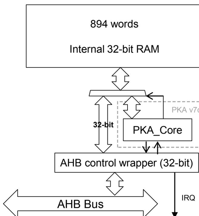
Figure 25. Block diagram shows the block diagram of the Public Key Accelerator.
Figure 25. Block diagram
graph TD
    RAM["894 words
Internal 32-bit RAM"] <--> PKA_Core
    subgraph PKA_v7c ["PKA v7c"]
        PKA_Core
    end
    PKA_Core <--> AHB_Wrapper["AHB control wrapper (32-bit)"]
    AHB_Wrapper <--> AHB_Bus["AHB Bus"]
    AHB_Wrapper --> IRQ
    PKA_Core <--> |32-bit| AHB_Wrapper
PKA can be used for accelerating Rivest, Shamir and Adleman (RSA), Diffie-Hellman (DH) and Elliptic Curve Cryptography (ECC) operations over a \( GF(p) \) field for operand sizes up to 3136 bits for RSA and DH, and up to 640 bits for ECC.
A memory of 3576 bytes (894 words of 32 bits) is used for providing initial data to the PKA, and for holding the results after computation is completed. This memory is called PKA RAM. Access is done through the PKA AHB interface.
A typical computing sequence by the PKA is composed by the following steps:
- 1. Calculation of \( R2 \pmod n \) parameter to enter the Montgomery domain
- 2. Conversion of inputs into the Montgomery residue-system representation
- 3. Computation of the requested primitive (modular exponentiation for RSA/DH and point multiplication for ECC)
- 4. Conversion out from Montgomery representation
If several operations are computed sequentially using the same modulus \( n \) , the first step can be skipped, since the PKA can store the last computed \( R2 \pmod n \) . User software is also able to load precomputed values of \( R2 \pmod n \) directly into the PKA.
13.3.1 Enabling/disabling PKA
Setting the EN bit (PKA_CR[0]) to '1' enables the PKA peripheral. When EN='0', the PKA peripheral is reset, no operation can be started, and the PKA memory cannot be accessed.
Clearing EN bit while a calculation is in progress causes the operation to be aborted. In this case, the content of the PKA RAM (described here below) is not guaranteed.
13.3.2 PKA RAM
The PKA RAM is an internal memory block of 3576 bytes which is organized as 894 words of 32 bits. Each 32-bit word has an address associated with it, from decimal offset 0 to 893.
The offset address to access the first word of the memory block is 0x400. External masters may access this internal memory block from the PKA AHB interface.
Note: Only 32 bits access are supported.
Accesses are allowed only while there is no computation in progress (BUSY = 0). During computation the internal memory block is accessed by the PKA core itself.
13.3.3 Executing a PKA operation
PKA is able to perform 18 types of operations. Each of those PKA operations is executed using the following procedure:
- 1. Load initial data into the PKA internal RAM.
- 2. Load the MODE[5:0] field specifying the operation to be executed and assert the START bit. Both fields are in the PKA_CR register.
- 3. Wait until the PROCENDF bit in the PKA_SR register is set, which indicates that the computation is complete.
- 4. Read the result data from the PKA internal RAM.
The operations and their corresponding input data and results are described in Section 13.4: Operating modes .
13.3.4 Security level
The PKA device offers a countermeasure to thwart side band channel attack. This protection can be activated by setting the bit SEC_LVL in the PKA_CR register. One must know that this specific protection mode increases the processing time by 25% on average.
13.3.5 PKA error management
When PKA is used some errors can occur:
- • The access to PKA RAM falls outside the expected range or access to PKA registers falls outside the expected range. In this case the Address Error flag (ADDRERRF) is set in the PKA_SR register
- • An AHB access to the PKA RAM occurred while the PKA core was using it. In this case the RAM Error Flag (RAMERRF) is set in the PKA_SR register, reads to PKA RAM return zero, while writes are ignored.
For each error flag above, PKA generates an interrupt if the application sets the corresponding bit in PKA_CR register (see Section 13.5.1: PKA interrupts for details).
ADDRERRF and RAMERRF errors are cleared by setting the corresponding bit in PKA_CLRFR.
The PKA can be re-initialized at any moment by resetting the EN bit in the PKA_CR register.
13.4 Operating modes
There are 18 types of operations that the PKA can perform. Each of these operating modes has an associated code which is to be written to the MODE[5:0] field in the PKA_CR register.
Table 35. Operating modes
| MODE[5:4] | MODE[3:0] | Operation performed |
|---|---|---|
| 00 | 0000 | Compute Montgomery parameter and modular exponentiation |
| 00 | 0001 | Compute Montgomery parameter |
| 00 | 0010 | Compute modular exponentiation only (Montgomery parameter should be loaded) |
| 10 | 0000 | Compute Montgomery parameter and compute ECC kP operation |
| 10 | 0010 | Compute the ECC kP primitive only (Montgomery parameter should be loaded) |
| 10 | 0100 | ECDSA sign |
| 10 | 0110 | ECDSA verification |
| 10 | 1000 | Point Check |
| 00 | 0111 | RSA CRT exponentiation |
| 00 | 1000 | Modular inversion |
| 00 | 1001 | Arithmetic addition |
| 00 | 1010 | Arithmetic subtraction |
| 00 | 1011 | Arithmetic multiplication |
| 00 | 1100 | Comparison |
| 00 | 1101 | Modular reduction |
| 00 | 1110 | Modular addition |
| 00 | 1111 | Modular subtraction |
| 01 | 0000 | Montgomery multiplication |
The format of the input data and the results in the PKA RAM are specified for each operating mode in the following sections.
The size of the operands is configurable. For RSA operations (where MODE[5]=0), the maximum “rsa_size” is 3136 bits. For ECC operations (where MODE[5]=1), the maximum “ecc_size” is 640.
In the tables below, the acronyms ROS (RSA operand size) and EOS (ECC operand size) indicate how many words the given field includes.
Fractional results are rounded up to the nearest integer since the PKA's processing is based on 32-bit words. The maximum ROS is 99 (3136-bit maximum exponent size), while the maximum EOS is 21 (640-bit maximum operand size).
For example, if you want to compute RSA with an operand of 1024 bits, then ROS equals 33. If you want to compute ECC with an operand of 192 bits, then EOS = 7.
Note: For the input fields whose size is ROS, ROS/2, or EOS, an additional word which is entirely zeros must be written after the last word. For example, to prepare for the calculation of the Montgomery parameter, ROS words are written for the modulus starting at address 305 until address 305+ROS-1. A word of all zeros must also be written at address 305+ROS before starting the calculation.
13.4.1 Compute Montgomery parameter
During this operation the PKA computes the Montgomery parameter \( R^2 \pmod n \) .
Table 36. Montgomery parameter input data
| Input data | Decimal address | Hexadecimal offset in PKA | Size (words) |
|---|---|---|---|
| Number of bits of the modulus | 1 | 0x00404 | 1 |
| Modulus 'n' | 599 | 0x0D5C | ROS |
Table 37. Montgomery parameter output data
| Output data | Decimal address | Hexadecimal offset in PKA | Size (words) |
|---|---|---|---|
| Montgomery parameter | 101 | 0x0594 | ROS |
Note: Computation of the Montgomery parameter depends on the word size of the core, so for a given modulus the core produces a different Montgomery parameter with word size = 64 than with word size = 32.
13.4.2 Compute modular exponentiation
During this operation the PKA computes the modular exponentiation \( m^e \pmod n \) .
Table 38. Modular exponentiation input data
| Input data | Decimal address | Hexadecimal offset in PKA | Size (words) |
|---|---|---|---|
| Number of bits of the exponent 'e' | 0 | 0x0400 | 1 |
| Number of bits of the operands 'm' | 1 | 0x0404 | 1 |
| Storage area for Montgomery parameter. Must be used if MODE[5:0]="000010" (modular exponentiation only) | 101 | 0x0594 | ROS |
| Base of the exponentiation 'm' | 401 | 0x0A44 | ROS |
| Exponent to process 'e' | 500 | 0x0BD0 | ROS |
| Modulus 'n' | 599 | 0x0D5C | ROS |
Table 39. Modular exponentiation output data
| Output data decimal address | Hexadecimal | Offset in PKA | Size (words) |
|---|---|---|---|
| Storage area for Montgomery parameter (OPTIONAL) | 101 | 0x0594 | ROS |
| S and M algorithm accumulator1 (result of the exponentiation) | 201 | 0x0724 | ROS |
| S and M algorithm accumulator2 (square) | 301 | 0x08B4 | ROS |
| Base of the exponentiation 'm' | 401 | 0x0A44 | ROS |
| S and M algorithm accumulator3 (dummy if sec_level=1) | 699 | 0x0EEC | ROS |
Note: The core supports only odd modulus. If modulus randomization is applied, the randomized modulus has to be an odd number. Both exponent and operand are unsigned integers represented in binary form on 32 bits. Both must be less or equal to max_rsa_size (3136).
13.4.3 Compute the ECC scalar multiplication
During this operation the PKA computes the ECC scalar multiplication \( kP \) .
Table 40. ECC scalar multiplication input data
| Input data | Decimal address | Hexadecimal offset in PKA | Size (words) |
|---|---|---|---|
| Number of bits of 'k' | 0 | 0x0400 | 1 |
| Number of bits of the modulus GF(p). For NIST P-256 value is 256. | 1 | 0x0404 | 1 |
| ECC curve 'a' coefficient sign. 0x0: positive; 0x1:negative For NIST curves over prime fields value is 0x1. | 2 | 0x0408 | 1 |
| ECC curve 'a' coefficient absolute value. For NIST curves over prime fields value is 0x3. | 3 | 0x040C | EOS |
| ECC curve prime modulus 'p' | 24 | 0x0460 | EOS |
| Storage area for Montgomery Parameter. Must be used if MODE[5:0]="100010" (scalar multiplication only). | 45 | 0x04B4 | EOS |
| The 'k' of \( kP \) | 66 | 0x0508 | EOS |
| Initial point 'P' coordinates | |||
| X | 87 | 0x055C | EOS |
| Y | 108 | 0x05B0 | EOS |
Table 41. ECC scalar multiplication output data
| Output data | Decimal address | Hexadecimal offset in PKA | Size (words) |
|---|---|---|---|
| Coordinates of the result | |||
| X | 87 | 0x055C | EOS |
| Y | 108 | 0x05B0 | EOS |
| Coordinates of last double | |||
| X1 | 634 | 0x0DE8 | EOS |
| Y1 | 655 | 0x0E3C | EOS |
| Z1 | 676 | 0x0E90 | EOS |
| Coordinates of check point | |||
| X2 | 697 | 0x0EE4 | EOS |
| Y2 | 718 | 0x0F38 | EOS |
| Z2 | 739 | 0x0F8C | EOS |
Note: The core supports only prime modulus; it is not possible to apply modulus randomization. The input value \( k \) is required to be greater than zero. If the user wants to execute the side channel protection known as scalar blinding (where the scalar 'k' is randomized via the addition of a multiple of the order of the curve \( n \) ), the PKA core is not able to deal with the case where the internal temporary result falls in the point at infinity. It is very unlikely to fall in the point at infinity, but it is possible to check that this inconvenience has happened by checking the final result. I.e. if the temporary result is equal to the point at infinity, the final result has both coordinates \( x \) and \( y \) equal to zero, that is not a point on the curve. When the scalar 'k' is smaller than the order, it is not possible to reach the point at infinity.
13.4.4 Point check
During this operation the PKA computes a boolean informing whether the given point P satisfies the curve over prime fields equation or not. If output error is equal to zero the point is on the curve.
Table 42. Point check input data
| Input data | Decimal address | Hexadecimal offset in PKA | Size (words) |
|---|---|---|---|
| Number of bits of the modulus GF(p). For NIST P-256 value is 256. | 1 | 0x0404 | 1 |
| ECC curve 'a' coefficient sign. 0x0: positive; 0x1:negative For NIST curves over prime fields value is 0x1. | 2 | 0x0408 | 1 |
| ECC curve 'a' coefficient absolute value. | 3 | 0x040C | EOS |
| ECC curve 'b' coefficient absolute value. | 255 | 0x07FC | EOS |
| ECC curve prime modulus 'p' | 24 | 0x0460 | EOS |
| The point 'P' coordinates X Y | 87 108 | 0x055C 0x05B0 | EOS EOS |
Table 43. Point check output data
| Output data | Decimal address | Hexadecimal offset in PKA | Size (words) |
|---|---|---|---|
| Error output result. If it is different from zero the point 'P' is not on the curve. | 0 | 0x0400 | 1 |
Note: Coordinates X and Y of the point P must be smaller than the modulus.
13.4.5 ECDSA sign
During this operation the PKA computes a signed message using elliptic curves over prime fields.
Table 44. ECDSA sign input data
| Input data | Decimal address | Hexadecimal offset in PKA | Size (words) |
|---|---|---|---|
| Number of bits of the order. For SHA-256 value is 256. | 1 | 0x0400 | 1 |
| Number of bits of the modulus GF(p). For NIST P-256 value is 256. | 1 | 0x404 | 1 |
| ECC curve 'a' coefficient sign. 0x0: positive 0x1: negative For NIST curves over prime fields value is 0x1. | 2 | 0x408 | 1 |
| ECC curve 'a' coefficient absolute value. For NIST curves over prime fields value is 0x3. | 3 | 0x040C | EOS |
| ECC curve prime modulus 'p' | 24 | 0x0460 | EOS |
| Random integer 'k' generated outside the PKA for this ECDSA signature | 66 | 0x0508 | EOS |
| The initial point 'P' coordinates | |||
| X | 87 | 0x055C | EOS |
| Y | 108 | 0x05B0 | EOS |
| Hash of the message 'e' | 634 | 0x0DE8 | EOS |
| Private key 'd' | 655 | 0x0E3C | EOS |
| Integer prime order of the curve 'n' | 677 | 0x0E94 | EOS |
Table 45. ECDSA sign output data
| Output data | Decimal address | Hexadecimal offset in PKA | Size (words) |
|---|---|---|---|
| Error output result. If it is different from zero, a new 'k' should be generated and ECDSA sign operation needs to be repeated | 698 | 0x0EE8 | 1 |
| Signature part 'r' | 192 | 0x0700 | EOS |
| Signature part 's' | 213 | 0x0754 | EOS |
| The final point 'kP' (optional) | |||
| X | 783 | 0x103C | EOS |
| Y | 804 | 0x1090 | EOS |
Note:
The prime modulus for P-256 curve is
\(
p = 2^{256} - 2^{224} + 2^{192} + 2^{96} - 1
\)
which corresponds to hexadecimal value
0xFFFFFFFF 00000001 00000000 00000000 00000000 FFFFFFFF FFFFFFFF FFFFFFFF
.
13.4.6 ECDSA verification
During this operation the PKA computes a boolean informing whether given signature is valid or not. This signature is based on an elliptic curve over prime fields.
If output error is equal to zero the signature is valid.
Table 46. ECDSA verification input data
| Input data | Decimal address | Hexadecimal offset in PKA | Size (words) |
|---|---|---|---|
| Number of bits of the order. For SHA-256 value is 256. | 1 | 0x0404 | 1 |
| Number of bits of the modulus GF(p). For NIST P-256 value is 256. | 45 | 0x04B4 | 1 |
| ECC curve 'a' coefficient sign. 0x0: positive; 0x1: negative For NIST curves over prime fields value is 0x1. | 23 | 0x045C | 1 |
| ECC curve 'a' coefficient absolute value. For NIST curves over prime fields value is 0x3. | 24 | 0x0460 | EOS |
| ECC curve prime modulus 'p' | 46 | 0x04B8 | EOS |
| The initial point 'P' coordinates | |||
| X | 122 | 0x05E8 | EOS |
| Y | 143 | 0x063C | EOS |
| Public key point 'Qa' coordinates | |||
| X | 720 | 0x0F40 | EOS |
| Y | 741 | 0x0F94 | EOS |
| Signature part 'r' | 806 | 0x1098 | EOS |
| Signature part 's' | 401 | 0x0A44 | EOS |
| Hash of the message 'e' | 762 | 0x0FE8 | EOS |
| Integer prime order of the curve 'n' | 599 | 0x0D5C | EOS |
Table 47. ECDSA verification output data
| Output data | Decimal address | Hexadecimal offset in PKA | Size (Words) |
|---|---|---|---|
| Error output result. If it is different from 0, the signature is not verified. | 108 | 0x05B0 | 1 |
13.4.7 RSA CRT exponentiation
During this operation the PKA computes the Chinese Remainder Theorem (CRT) optimization.
Table 48. RSA CRT exponentiation input
| Input data | Decimal address | Hexadecimal offset in PKA | size (words) |
|---|---|---|---|
| Number of bits of the operands | 1 | 0x0404 | 1 |
| CRT parameter 'Dp' | 151 | 0x065C | ROS/2 |
| CRT parameter 'Dq' | 500 | 0x0BD0 | ROS/2 |
| CRT parameter 'qInv' | 251 | 0x07EC | ROS/2 |
| Prime 'p' | 351 | 0x097C | ROS/2 |
| Prime 'q' | 599 | 0x0D5C | ROS/2 |
| Base of the exponentiation | 699 | 0x0EEC | ROS |
Table 49. RSA CRT exponentiation output data
| Output data | Decimal address | Hexadecimal offset in PKA | Size (words) |
|---|---|---|---|
| Operation result | 201 | 0x0724 | ROS |
Note: CRT is supported for modulus up to 3072 bits, with prime p and q of the same length i.e. half of the length of the modulus.
13.4.8 Modular reduction
During this operation the PKA computes a modular reduction.
Table 50. Modular reduction input data
| Input data | Decimal address | Hexadecimal offset in PKA | Size (words) |
|---|---|---|---|
| Operand length | 0 | 0x0400 | 1 |
| Operand | 301 | 0x08B4 | ROS |
| Modulus length | 1 | 0x0404 | 1 |
| Modulus | 401 | 0x0A44 | ROS |
Table 51. Modular reduction output data
| Output data | Decimal address | Hexadecimal offset in PKA | Size (words) |
|---|---|---|---|
| Operation result | 500 | 0x0BD0 | ROS |
13.4.9 Arithmetic addition
During this operation the PKA computes the arithmetic addition of two inputs, op1 and op2.
Table 52. Arithmetic addition input data
| Input data | Decimal address | Hexadecimal offset in PKA | Size (words) |
|---|---|---|---|
| Operand length | 1 | 0x0400 | 1 |
| op1 | 301 | 0x08B4 | ROS |
| op2 | 401 | 0x0A44 | ROS |
Table 53. Arithmetic addition output data
| Output data | Decimal address | Hexadecimal offset in PKA | Size (words) |
|---|---|---|---|
| Operation result: op1 + op2 | 500 | 0x0BD0 | ROS+1 |
13.4.10 Arithmetic Subtraction
During this operation the PKA computes the arithmetic subtraction of two inputs, op1 and op2.
Table 54. Arithmetic subtraction input data
| Input data | Decimal address | Hexadecimal offset in PKA | Size (words) |
|---|---|---|---|
| Operand length | 1 | 0x0400 | 1 |
| op1 | 301 | 0x08B4 | ROS |
| op2 | 401 | 0x0A44 | ROS |
Table 55. Arithmetic subtraction output data
| Output data | Decimal address | Hexadecimal offset in PKA | size (words) |
|---|---|---|---|
| Operation result: op1 - op2 | 500 | 0x0BD0 | ROS |
13.4.11 Comparison
During this operation, given two inputs op1 and op2, the PKA computes comparisons as follow:
- • If op1 = op2, then the result = 0
- • If op1 > op2, then the result = 1
- • If op1 < op2, then the result = 2
Table 56. Comparison input data
| Input data | Decimal address | Hexadecimal offset in PKA | size (words) |
|---|---|---|---|
| Operand length | 1 | 0x0400 | 1 |
| op1 | 301 | 0x08B4 | ROS |
| op2 | 401 | 0x0A44 | ROS |
Table 57. Comparison output data
| Output data | Decimal address | Hexadecimal offset in PKA | Size (words) |
|---|---|---|---|
| Operation result: If op1 = op2, then result = 0 If op1 > op2, then result = 1 If op1 < op2, then result = 2 | 500 | 0x0BD0 | 1 |
13.4.12 Arithmetic multiplication
During this operation the PKA computes the arithmetic multiplication of two inputs, op1 and op2.
Table 58. Arithmetic multiplication input data
| Input data | Decimal address | Hexadecimal offset in PKA | Size (words) |
|---|---|---|---|
| Operand length | 1 | 0x0400 | 1 |
| op1 | 301 | 0x08B4 | ROS |
| op2 | 401 | 0x0A44 | ROS |
Table 59. Arithmetic multiplication output data
| Output data | Decimal address | Hexadecimal offset in PKA | Size (words) |
|---|---|---|---|
| Operation result: op1 x op2 | 500 | 0x0BD0 | 2*ROS |
13.4.13 Modular addition
During this operation the PKA computes the addition of op1 by op2 modulus op3.
Table 60. Modular addition input data
| Input data | Decimal address | Hexadecimal offset in PKA | Size (words) |
|---|---|---|---|
| Operand length | 1 | 0x0400 | 1 |
| op1 | 301 | 0x08B4 | ROS |
| op2 | 401 | 0x0A44 | ROS |
| op3 (modulus) | 599 | 0x0D5C | ROS |
Table 61. Modular addition output data
| Output data | Decimal address | Hexadecimal offset in PKA | Size (words) |
|---|---|---|---|
| Operation result: (op1 + op2) mod op3 | 500 | 0x0BD0 | ROS |
13.4.14 Modular inversion
During this operation the PKA computes the inversion of op1 modulus op2. Note that op1 must be smaller than the modulus op2.
Table 62. Modular inversion input data
| Input data | Decimal address | Hexadecimal offset in PKA | Size (words) |
|---|---|---|---|
| Operand length | 1 | 0x0400 | 1 |
| op1 | 301 | 0x08B4 | ROS |
| op2 (modulus) | 401 | 0x0A44 | ROS |
Table 63. Modular inversion output data
| Output data | Decimal address | Hexadecimal offset in PKA | Size (words) |
|---|---|---|---|
| Operation result | 500 | 0x0BD0 | ROS |
Note: The operand to invert should be coprime with the modulus. In case this is not known, and the operand is a divisor of the modulus, the result is a multiple of a factor of the modulus.
13.4.15 Modular subtraction
During this operation the PKA computes the subtraction of op1 by op2 modulus op3.
Table 64. Modular subtraction input data
| Input data | Decimal address | Hexadecimal offset in PKA | Size (words) |
|---|---|---|---|
| Operand length | 1 | 0x0400 | 1 |
| op1 | 301 | 0x08B4 | ROS |
| op2 | 401 | 0x0A44 | ROS |
| op3 (modulus) | 599 | 0x0D5C | ROS |
Table 65. Modular subtraction output data
| Output data | Decimal address | Hexadecimal offset in PKA | Size (words) |
|---|---|---|---|
| Operation result: (op1 - op2) mod op3 | 500 | 0x0BD0 | ROS |
Note: Reduction happens when op2 is larger than op1. The result is always smaller than op3 and equal or larger than zero.
13.4.16 Montgomery multiplication
During this operation the PKA computes the multiplication of op1 by op2 modulus op3 in the Montgomery space. Before issuing this operation the PKA needs to set some internal registers, which can be done by issuing a Montgomery parameter computation, an ECC scalar multiplication or any ECC operation.
Table 66. Montgomery multiplication input data
| Input data | Decimal address | Hexadecimal offset in PKA | Size (words) |
|---|---|---|---|
| Operand length | 1 | 0x0400 | 1 |
| op1 | 301 | 0x08B4 | ROS |
| op2 | 401 | 0x0A44 | ROS |
| op3 (modulus) | 599 | 0x0D5C | ROS |
Table 67. Montgomery multiplication output data
| Output data | Decimal address | Hexadecimal offset in PKA | Size (words) |
|---|---|---|---|
| Operation result | 500 | 0x0BD0 | ROS |
Note: In order to convert a number from natural representation to Montgomery domain it is necessary to perform a Montgomery multiplication between the number and the Montgomery parameter (called also \( R^2 \bmod n \) ). Besides, in order to convert a number from Montgomery domain to natural domain a Montgomery multiplication between the Montgomery number and one has to be computed.
13.5 Processing time
The following tables summarize the PKA computation times, expressed in clock cycles.
Table 68. Modular exponentiation
| Exponent length (in bits) | Mode | Operand length (in bits) | ||
|---|---|---|---|---|
| 1024 | 2048 | 3072 | ||
| 3 | Normal | 152000 | 407000 | 864000 |
| Fast | 23000 | 82000 | 178000 | |
| 17 | Normal | 163000 | 448000 | 955000 |
| Fast | 34000 | 123000 | 267000 | |
| \( 2^{16}+1 \) | Normal | 208000 | 611000 | 1308000 |
| Fast | 79000 | 286000 | 622000 | |
| 1024 | Normal | 5832000 | - | - |
| Fast | 5640000 | - | - | |
| 2048 | Normal | - | 41917000 | - |
| Fast | - | 41023000 | - | |
| 3072 | Normal | - | - | 137477000 |
| Fast | - | - | 136761000 | |
Table 69. ECC scalar multiplication
| Mode | Modulus length (in bits) | ||||||
|---|---|---|---|---|---|---|---|
| 160 | 192 | 256 | 320 | 384 | 512 | 521 | |
| Normal | 817000 | 1250000 | 2462000 | 4254000 | 6821000 | 14445000 | 16580000 |
| Fast | 815000 | 1247000 | 2458000 | 4247000 | 6807000 | 14421000 | 16579000 |
Note: These times depend on the number of “1”s included in the scalar parameter.
Table 70. ECDSA signature average computation time
| Modulus length (in bits) | ||||||
|---|---|---|---|---|---|---|
| 160 | 192 | 256 | 320 | 384 | 512 | 521 |
| 880000 | 1332000 | 2645000 | 4508000 | 7298000 | 15309000 | 17770000 |
Note: These values are average execution times of random moduli of given length, as they depend upon the length and the value of the modulus. The execution time for the moduli that define the finite field of NIST elliptic curves is shorter than that needed for the moduli used for Brainpool elliptic curves or for random moduli of the same size.
Table 71. ECDSA verification average computation times
| Modulus length (in bits) | ||||||
|---|---|---|---|---|---|---|
| 160 | 192 | 256 | 320 | 384 | 512 | 521 |
| 1750000 | 2675000 | 5249000 | 9063000 | 14559000 | 30673000 | 35794000 |
| Modulus length (in bits) | |||||||||
|---|---|---|---|---|---|---|---|---|---|
| 160 | 192 | 256 | 320 | 384 | 512 | 521 | 1024 | 2048 | 3072 |
| 2259 | 3923 | 5924 | 7451 | 10841 | 17506 | 32000 | 59768 | 233073 | 552321 |
Note: The computation times depend upon the length and the value of the modulus, hence these values are average execution times of random moduli of given length.
13.5.1 PKA interrupts
There are three individual maskable interrupt sources generated by the public key accelerator when enabled by EN bit, signaling the following events:
- 1. Access to unmapped address (ADDRERRF), see Section 13.3.5: PKA error management
- 2. PKARAM access while PKA operation is in progress (RAMERRF), see Section 13.3.5: PKA error management
- 3. PKA end of operation (PROCENDF)
Three interrupt sources are connected to the same global interrupt request signal pka_it. The user can enable or disable the above interrupt sources individually by changing the mask bits in Section 13.6.1: PKA control register (PKA_CR) . Setting the appropriate mask bit to 1 enables the interrupt. The status of the individual interrupt events can be read from the PKA status register (PKA_SR), and it is cleared in the PKA_CLRFR register.
Table 73. PKA interrupt requests gives a summary of the available features.
Table 73. PKA interrupt requests
| Interrupt event | Event flag | Enable control bit |
|---|---|---|
| Access to unmapped address error | ADDRERRF | ADDRERRIE |
| PKA RAM access error | RAMERRF | RAMERRIE |
| PKA end of operation | PROCENDF | PROCENDIE |
13.6 PKA registers
13.6.1 PKA control register (PKA_CR)
Address offset: 0x00
Reset value: 0x0000 0000
| 31 | 30 | 29 | 28 | 27 | 26 | 25 | 24 | 23 | 22 | 21 | 20 | 19 | 18 | 17 | 16 |
|---|---|---|---|---|---|---|---|---|---|---|---|---|---|---|---|
| Res. | Res. | Res. | Res. | Res. | Res. | Res. | Res. | Res. | Res. | Res. | ADDR ERRIE | RAM ERRIE | Res. | PROC ENDIE | Res. |
| rw | rw | rw | |||||||||||||
| 15 | 14 | 13 | 12 | 11 | 10 | 9 | 8 | 7 | 6 | 5 | 4 | 3 | 2 | 1 | 0 |
| Res. | Res. | Mode | Res. | Res. | Res. | Res. | Res. | SECLVL | START | NE | |||||
| rw | rw | rw | rw | rw | rw | rw | rw | rw | |||||||
| Bits 31:21 | Reserved, must be kept at zero |
| Bit 20 | ADDRERRIE
: Address error interrupt enable
|
| Bit 19 | RAMERRIE
: RAM error interrupt enable
|
| Bit 18 | Reserved, must be kept at zero |
| Bit 17 | PROCENDI
: End of operation interrupt enable
|
| Bit 16:14 | Reserved, must be kept at zero |
| Bit 13:8 | MODE [5:0]
: PKA operation code
|
| Bit 7:3 | Reserved, must be kept at zero |
| Bit 2 | SECLVL
: Security enable
|
| |
| Bit 1 | START : start the operation Writing '1' to this bit starts the operation which is selected by MODE[5:0], using the operands and data already written to the PKA RAM. This bit is always read as '0'. Note: START is ignored if PKA is busy. |
| Bit 0 | EN : peripheral enable
|
13.6.2 PKA status register (PKA_SR)
Address offset: 0x04
Reset value: 0x0000 0000
| 31 | 30 | 29 | 28 | 27 | 26 | 25 | 24 | 23 | 22 | 21 | 20 | 19 | 18 | 17 | 16 |
|---|---|---|---|---|---|---|---|---|---|---|---|---|---|---|---|
| Res. | Res. | Res. | Res. | Res. | Res. | Res. | Res. | Res. | Res. | Res. | ADDR ERRF | RAM ERRF | Res. | PROC ENDF | BUSY |
| r | r | r | r | ||||||||||||
| 15 | 14 | 13 | 12 | 11 | 10 | 9 | 8 | 7 | 6 | 5 | 4 | 3 | 2 | 1 | 0 |
| Res. | Res. | Res. | Res. | Res. | Res. | Res. | Res. | Res. | Res. | Res. | Res. | Res. | Res. | Res. | Res. |
| Bits 31:21 | Reserved, must be kept at zero |
| Bit 20 | ADDRERRF
: Address error flag
|
| Bit 19 | RAMERRF
: PKA RAM error flag
|
| Bit 18 | Reserved, must be kept at zero |
| Bit 17 | PROCENDF
: PKA end of operation flag
|
| Bit 16 | BUSY
: PKA operation is in progress This bit is set to '1' whenever START bit in the PKA_CR is set. It is automatically cleared when the computation is complete, meaning that PKA RAM can be safely accessed and a new operation can be started.
|
| Bit 15 | Reserved, must be kept zero |
13.6.3 PKA clear flag register (PKA_CLRFR)
Address offset: 0x08
Reset value: 0x0000 0000
| 31 | 30 | 29 | 28 | 27 | 26 | 25 | 24 | 23 | 22 | 21 | 20 | 19 | 18 | 17 | 16 |
|---|---|---|---|---|---|---|---|---|---|---|---|---|---|---|---|
| Res. | Res. | Res. | Res. | Res. | Res. | Res. | Res. | Res. | Res. | Res. | ADDR ERRFC | RAM ERRFC | Res. | PROC ENDFC | Res. |
| w_r0 | w_r0r | w_r0 | |||||||||||||
| 15 | 14 | 13 | 12 | 11 | 10 | 9 | 8 | 7 | 6 | 5 | 4 | 3 | 2 | 1 | 0 |
| Res. | Res. | Res. | Res. | Res. | Res. | Res. | Res. | Res. | Res. | Res. | Res. | Res. | Res. | Res. | Res. |
| Bits 31:21 | Reserved, must be kept at zero |
| Bit 20 | ADDRERRFC
: Clear address error flag
|
| Bit 19 | RAMERRFC
: Clear PKA RAM error flag
|
| Bit 18 | Reserved, must be kept at zero |
| Bit 17 | PROCENDFC
: Clear PKA end of operation flag
|
| Bit 16:0 | Reserved, must be kept at zero Note: reading PKA_CLRFR returns all zeroes |
13.6.4 PKA RAM memory
Address offset: 0x400
The PKA_RAM is memory mapped at the offset address of 0x0400 compared to the PKA base address. Only word access (32 bits) are supported. RAM size is 3576 bytes (max. word offset: 0x11F4)
13.6.5 PKA register map
Table 74. PKA register map
| Offset | Register | 31 | 30 | 29 | 28 | 27 | 26 | 25 | 24 | 23 | 22 | 21 | 20 | 19 | 18 | 17 | 16 | 15 | 14 | 13 | 12 | 11 | 10 | 9 | 8 | 7 | 6 | 5 | 4 | 3 | 2 | 1 | 0 | |
|---|---|---|---|---|---|---|---|---|---|---|---|---|---|---|---|---|---|---|---|---|---|---|---|---|---|---|---|---|---|---|---|---|---|---|
| 0x0000 | PKA_CR | Res. | Res. | Res. | Res. | Res. | Res. | Res. | Res. | Res. | Res. | Res. | ADDRERRIE | RAMERRIE | Res. | PROCENDIE | Res. | Res. | Res. | MODE[5 : 0] | Res. | Res. | Res. | Res. | Res. | SCLVL | START | EN | ||||||
| Reset value | 0 | 0 | 0 | 0 | 0 | 0 | 0 | 0 | 0 | 0 | 0 | 0 | 0 | 0 | 0 | 0 | 0 | 0 | 0 | 0 | 0 | 0 | 0 | 0 | 0 | 0 | 0 | 0 | 0 | 0 | 0 | 0 | ||
| 0x0004 | PKA_SR | Res. | Res. | Res. | Res. | Res. | Res. | Res. | Res. | Res. | Res. | Res. | ADDRERRF | RAMERRF | Res. | PROCENDF | BUSY | Res. | Res. | Res. | Res. | Res. | Res. | Res. | Res. | Res. | Res. | Res. | Res. | Res. | Res. | Res. | Res. | Res. |
| Reset value | 0 | 0 | 0 | 0 | 0 | 0 | 0 | 0 | 0 | 0 | 0 | 0 | 0 | 0 | 0 | 0 | 0 | 0 | 0 | 0 | 0 | 0 | 0 | 0 | 0 | 0 | 0 | 0 | 0 | 0 | 0 | 0 | ||
| 0x0008 | PKA_CLRFR | Res. | Res. | Res. | Res. | Res. | Res. | Res. | Res. | Res. | Res. | Res. | ADDRERRFC | RAMERRFC | Res. | PROCENDFC | Res. | Res. | Res. | Res. | Res. | Res. | Res. | Res. | Res. | Res. | Res. | Res. | Res. | Res. | Res. | Res. | Res. | Res. |
| Reset value | 0 | 0 | 0 | 0 | 0 | 0 | 0 | 0 | 0 | 0 | 0 | 0 | 0 | 0 | 0 | 0 | 0 | 0 | 0 | 0 | 0 | 0 | 0 | 0 | 0 | 0 | 0 | 0 | 0 | 0 | 0 | 0 | ||