10. PTA converter (PTACONV)
10.1 PTACONV introduction
The PTA converter is used to convert the PTA information coming from the 2.4 GHz RADIO into the PTA protocol used on the PTA controller GPIOs.
10.2 PTACONV main features
- • Based on the IEEE802.15.2 standard
- • Supports both grant and deny signaling
- • Supports from 1- to 4-wire protocols
- • Programmable transmit/receive PTA_STATUS polarity
- • Programmable priority polarity
- • Programmable grant polarity
- • Programmable active polarity
- • Programmable PTA_ACTIVE timing
- • Programmable PTA_STATUS time-multiplexed priority timing
- • Programmable transmit packet abort
10.3 PTACONV functional description
The PTA converter adapts the PTA protocol to the various external PTA controllers. It supports a grant or deny signaling on the PTA_GRANT signal, and the following protocols:
- • 1-wire PTA_ACTIVE
- • 2-wire PT_ACTIVE and PTA_GRANT
- • 3-wire PTA_ACTIVE, PTA_GRANT, and time-multiplexed PTA_STATUS
- • 4-wire PTA_ACTIVE, PTA_GRANT, PTA_PRIORITY and PTA_STATUS
When the request to cease an ongoing transmission occurs near the end of the 2.4 GHz RADIO packet, PTA_ACTIVE is deactivated at the end of the packet, before the expiration of T4.
10.3.1 PTACONV block diagram
Figure 26 shows the PTA converter block diagram and the interface to the 2.4 GHz RADIO.
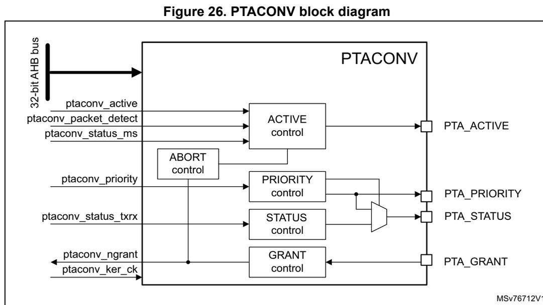
Figure 26. PTACONV block diagram
The diagram shows the internal architecture of the PTACONV block. A 32-bit AHB bus is connected to the top. Inside the block, there are five control units: ACTIVE control, PRIORITY control, STATUS control, GRANT control, and ABORT control. The ACTIVE control takes ptaconv_active, ptaconv_packet_detect, and ptaconv_status_ms as inputs and outputs PTA_ACTIVE. The PRIORITY control takes ptaconv_priority and ptaconv_status_txrx as inputs and outputs PTA_PRIORITY. The STATUS control takes ptaconv_status_ms and ptaconv_status_txrx as inputs and outputs PTA_STATUS. The GRANT control takes ptaconv_ngrant and ptaconv_ker_ck as inputs and outputs PTA_GRANT. The ABORT control is connected to the ACTIVE and PRIORITY controls. A multiplexer selects between the outputs of the PRIORITY and STATUS controls for the PTA_STATUS pin. The reference MSV76712V1 is noted in the bottom right.
The PTACONV is clocked by the 2.4 GHz RADIO kernel clock, independently from the hclk for the AHB interface used to access the PTACONV configuration registers.
10.3.2 PTACONV pins and internal signals
Table 86. 2.4 PTACONV input/output pins
| Pin name | Signal type | Description |
|---|---|---|
| PTA_ACTIVE | Output | PTA 2.4 GHz RADIO packet activation request |
| PTA_PRIORITY | Output | PTA 2.4 GHz RADIO packet priority |
| PTA_STATUS | Output | PTA 2.4 GHz RADIO packet type |
| PTA_GRANT | Input | PTA grant medium to 2.4 GHz RADIO |
Table 87. PTACONV internal input/output signals
| Pin name | Signal type | Description |
|---|---|---|
| ptaconv_active | Input | 2.4 GHz RADIO packet activation request |
| ptaconv_priority | Input | 2.4 GHz RADIO packet priority |
| ptaconv_status_txrx | Input | 2.4 GHz RADIO packet type Tx or Rx |
| ptaconv_status_ms | Input | 2.4 GHz RADIO packet type maser or slave |
| ptaconv_packet_detect | Input | 2.4 GHz RADIO packet detect |
| ptaconv_ngrant | Output | PTA active low medium granted |
Table 87. PTACONV internal input/output signals (continued)
| Pin name | Signal type | Description |
|---|---|---|
| ptaconv_ker_ck | Input | Kernel clock |
| AHB | Input/output | AHB bus interface |
10.3.3 PTACONV protocols
The PTA grant protocol, the PTA deny protocol, and the 3-wire PTA_STATUS time-multiplexed priority and status transmit receive information are detailed in this section.
PTA grant protocol
The 4-wire PTA grant protocol uses PTA_ACTIVE, PTA_STATUS, PTA_PRIORITY, and PTA_GRANT signals, as shown in Figure 27.
Figure 27. 4-wire PTA grant protocol
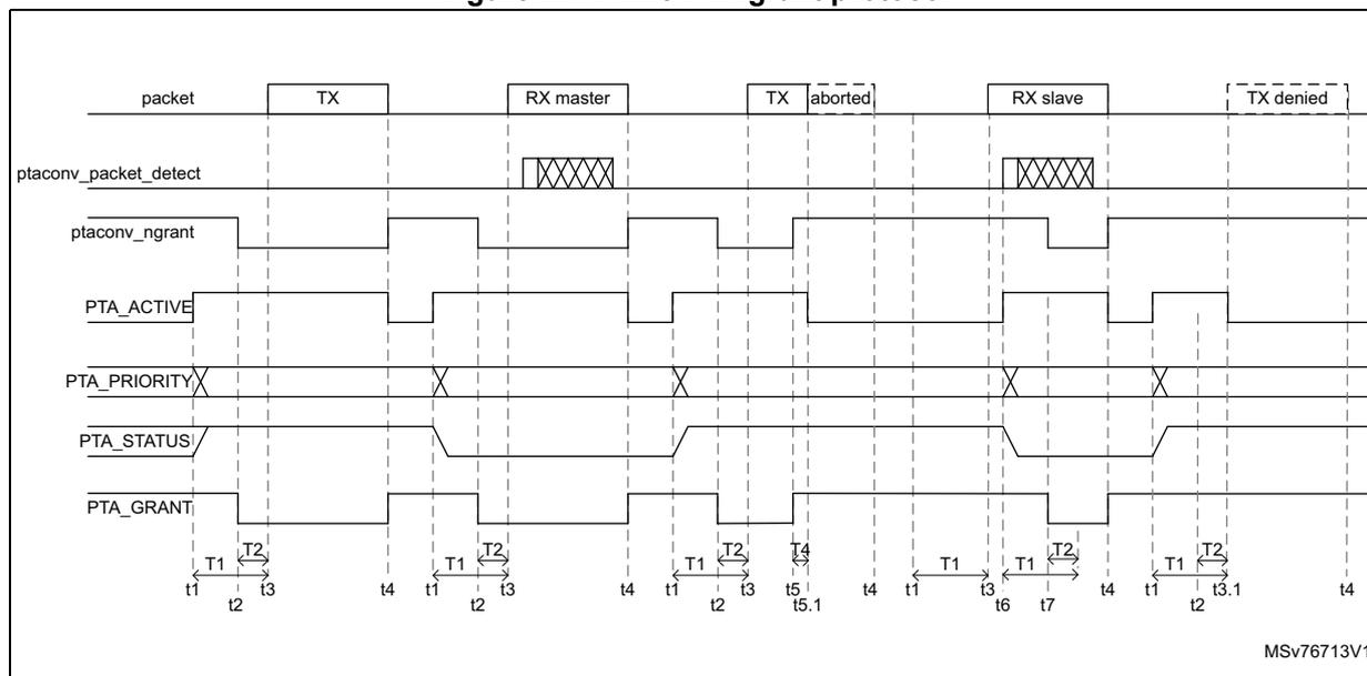
The diagram shows the interaction of seven signals over five scenarios: TX, RX master, TX aborted, RX slave, and TX denied.
- packet : Shows active high blocks for TX, RX master, TX aborted (shortened), RX slave, and TX denied (not started).
- ptaconv_packet_detect : Pulses high at the start of RX master and RX slave packets.
- ptaconv_ngrant : Active low signal indicating when the grant is given by the internal logic.
- PTA_ACTIVE : Driven high by the radio to request the medium. It precedes the packet by T1.
- PTA_PRIORITY : Pulses high at the start of a request to indicate priority level.
- PTA_STATUS : Pulses high to indicate status information.
- PTA_GRANT : Input to the radio indicating the medium is granted. It must be stable for T2 before the packet starts.
Timing parameters:
- • T1 is the time for the PTA_ACTIVE signal to request the medium before the start of the 2.4 GHz RADIO packet transfer.
- • T2 is the time before the start of the 2.4 GHz RADIO packet transfer, during which the PTA_GRANT is stable.
- • T4 is the delay time to cease an ongoing 2.4 GHz RADIO packet transmission and to deactivate PTA_ACTIVE.
Time instances:
- • t1: the request signal is activated before the 2.4 GHz RADIO packet transfer. For transmit and receive master packets, t1 is also the time PTA_ACTIVE is activated.
- • t2: PTA_GRANT signal is stable.
- • t3 start of the 2.4 GHz RADIO packet transfer.
- • t3.1: the 2.4 GHz RADIO packet transfer is denied, and PTA_ACTIVE is deactivated. The external PTA controller can remove the PTA_GRANT as well.
- • t4: indicates the end of the 2.4 GHz RADIO packet and the deactivation of the PTA_ACTIVE signal when active. The external PTA controller can remove the PTA_GRANT as well.
- • t5: PTA_GRANT goes to deny and requests to cease the ongoing packet transmission.
- • t5.1: indicates that the ongoing packet is aborted and the PTA_ACTIVE signal is deactivated. Abortion of the transmit packet can be disabled with register bit. ABORTDIS, in this case, the ngrant signal stays low until the end of the transmit packet.
- • t6: the receive packet has been detected and used for slave receive packets to activate the PTA_ACTIVE signal.
- • t7: PTA_GRANT is stable.
Receive packets are always granted and reception always proceeds. Receive packets use the PTA protocol to request the reservation of the medium for high priority receive packets.
PTA deny protocol
The PTA deny protocol uses PTA_ACTIVE, PTA_STATUS, PTA_PRIORITY and PTA_DENY signals, as shown in Figure 28.
Figure 28. 4-wire PTA deny protocol
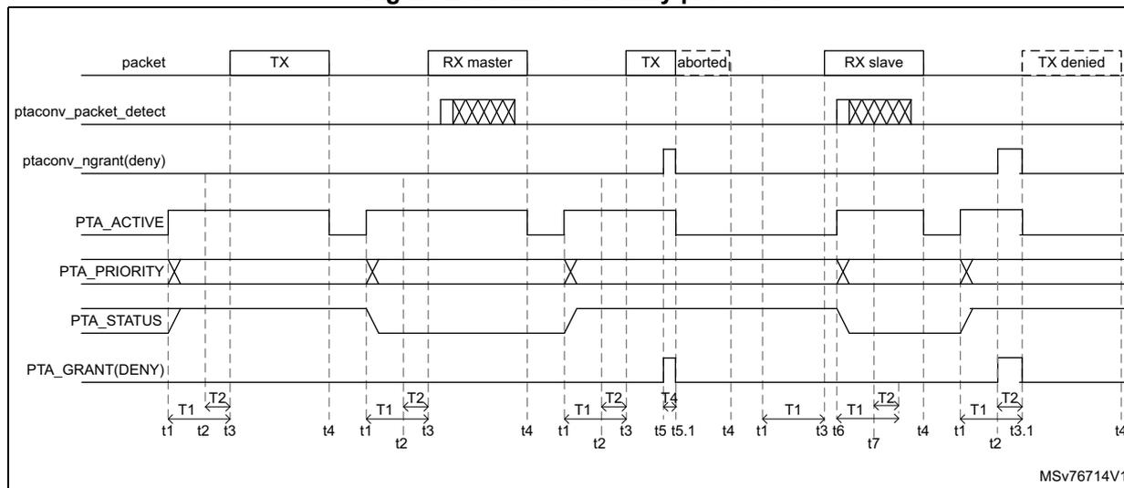
The diagram illustrates the timing of the 4-wire PTA deny protocol across five packet scenarios: TX, RX master, TX aborted, RX slave, and TX denied. The signals shown are:
- packet: TX, RX master, TX aborted, RX slave, TX denied.
- ptaconv_packet_detect: Shows active periods for RX master and RX slave packets.
- ptaconv_ngrant(deny): Signal that goes low to deny a transmit packet.
- PTA_ACTIVE: Request signal that goes high to request the medium.
- PTA_PRIORITY: Priority signal used during the request phase.
- PTA_STATUS: Status signal that goes low when the medium is granted.
- PTA_GRANT(DENY): Grant signal that goes high to grant the medium.
- T1: Time for PTA_ACTIVE to request the medium before the start of the packet transfer.
- T2: Time before the start of the packet transfer, during which PTA_GRANT is stable.
- T3: Start of the 2.4 GHz RADIO packet transfer.
- T4: End of the 2.4 GHz RADIO packet transfer.
- T5: Time when PTA_GRANT goes to deny.
- T5.1: Time when the ongoing packet is aborted.
- T6: Time when the receive packet has been detected.
- T7: Time when PTA_GRANT is stable.
- t1, t2, t3, t4, t5, t5.1, t6, t7: Time instances for the RX master and RX slave packets.
Timing parameters:
- • T1 is the time for the PTA_ACTIVE signal to request the medium before the start of the 2.4 GHz RADIO packet transfer.
- • T2 is the time before the start of the 2.4 GHz RADIO packet transfer, during which the PTA_GRANT is stable.
Time instances:
- • t1: the request signal is activated before the 2.4 GHz RADIO packet transfer. For transmit and receive master packets, t1 is also the time PTA_ACTIVE is activated.
- • t2: PTA_GRANT signal is stable.
- • t3: start of the 2.4 GHz RADIO packet transfer.
- • t3.1: a 2.4 GHz RADIO packet transfer is denied and the PTA_ACTIVE is deactivated. The external PTA controller can remove the PTA_GRANT as well.
- • t4: indicates the end of the 2.4 GHz RADIO packet and the deactivation of the PTA_ACTIVE signal when active. The external PTA controller too can remove the PTA_GRANT.
- • t5: PTA_GRANT goes to deny and requests to cease the ongoing packet transmission.
- • t5.1: indicates that the ongoing packet is aborted and the PTA_ACTIVE signal is deactivated. Abortion of the transmit packet can be disabled with register bit ABORTDIS, in this case, the deny signal stays high until the end of the transmit packet.
- • t6: the receive packet has been detected and used for slave receive packets to activate the PTA_ACTIVE signal.
- • t7: PTA_GRANT is stable.
Receive packets are always granted and reception always proceeds. Receive packets use the PTA protocol to request the reservation of the medium for high priority receive packets.
3-wire time shared PTA_STATUS
The 3-wire PTA protocol does not use the PTA_PRIORITY signal. The priority and transmit receive packet status information is time-multiplexed on the PTA_STATUS signal, as shown in Figure 29.
Figure 29. 3-wire time-multiplexed PTA_STATUS
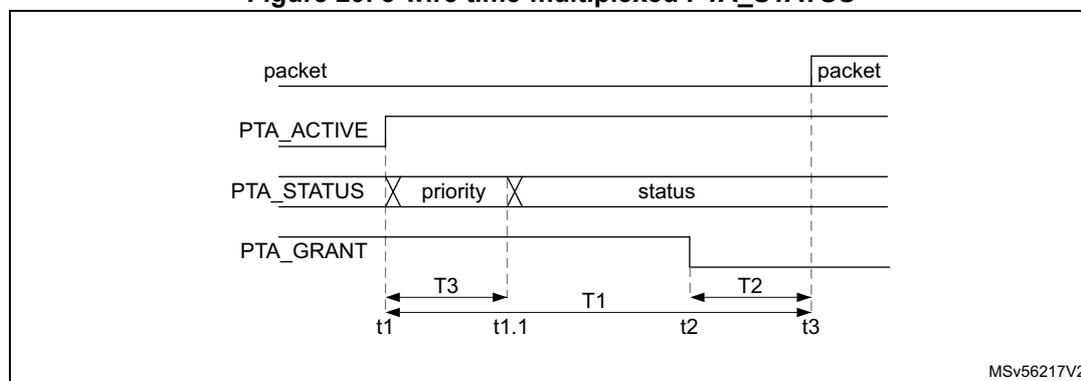
Timing parameters:
- • T1 is the time for the PTA_ACTIVE to request the medium before the start of the 2.4 GHz RADIO packet transfer.
- • T2 is the time before the start of the 2.4 GHz RADIO packet transfer during which the PTA_GRANT is stable.
- • T3 is the time that the priority is time-multiplexed on the PTA_STATUS signal.
Time instances:
- • t1: the request signal is activated before the 2.4 GHz RADIO packet transfer. For transmit and receive master packets, it is also the time PTA_ACTIVE is activated. Priority information is time-multiplexed on the PTA_STATUS signal.
- • t1.1: the transmit or receive status is time-multiplexed on the PTA_STATUS signal.
- • t2: PTA_GRANT signal is stable.
- • t3: start of the 2.4 GHz RADIO packet transfer.
PTA timing parameters
Table 88. 2.4 PTACONV timing parameters
| Symbol | Parameter | Min | Typ | Max | Unit |
|---|---|---|---|---|---|
| T1, T 1_PTA | PTA_ACTIVE setup time | 20 | - | 150 | µs |
| T 1_PTA_jitter | PTA_ACTIVE setup time jitter | -2 | - | 2 | |
| T2, T 2_PTA | PTA_GRANT setup time | 5 | - | - | |
| T3, T 3_PTA | PTA_STATUS priority valid time | 8 | - | 20 | |
| T4, T 4_PTA | Transmit packet abort delay | 5 | - | 10 |
10.3.4 PTACONV interface with the 2.4 GHz RADIO
The 2.4 GHz RADIO provides the following signals:
- • ptaconv_active:
- – activated with a T1 setup time before the start of the packet. This is before:
- The PA ramping for transmit packet
- The start of the receive window for receive packets
- – deactivated at the end of the scheduled packet. This is after:
- The PA has ramped down for transmit packets.
- The last receive packet bit has been received, or at the end of the review window when no packet is detected.
- – activated with a T1 setup time before the start of the packet. This is before:
- • ptaconv_priority: signaling 0 for low-priority packets, 1 for high priority packets
- • ptaconv_status_txrx: signaling 0 for receive packets, 1 for transmit packets
- • ptaconv_status_ms: signaling 0 for master packets, 1 for slave packets
- • ptaconv_packet_detect: receive packet (access code) detect indication
- • ptaconv_ngrant: active low grant signal
- – to be sampled during the valid window T2 to determine if a packet transmission is granted or denied
- – monitored during the transmit packet to cease transmission upon the reception of a deny
10.4 PTACONV low-power modes
The PTACONV supports operation in low power modes as shown in the table below:
Table 89. Effect of low-power modes on the PTACONV| Mode | Description |
|---|---|
| Sleep | No effect. PTACONV remains operational. |
| Stop 0 voltage scaling range 1 and 1.5 | No effect. PTACONV remains operational. |
| Stop 0 voltage range 2 and Stop 1 | The PTACONV register context is kept, PTA signals keep their values. |
| Stop 2, Stop 3 | The PTACONV is powered down, PTA signals keep their values when enabled in register PWR_S2RETR. |
| Standby retention, Standby | The PTACONV is powered down, PTA signals keep their values when enabled in register PWR_IORETENRx. |
10.5 PTACONV registers
10.5.1 PTACONV active control register (PTACONV_ACTCR)
Address offset: 0x000
Reset value: 0x00005 0014
Access: no wait state; word, half-word, and byte access
| 31 | 30 | 29 | 28 | 27 | 26 | 25 | 24 | 23 | 22 | 21 | 20 | 19 | 18 | 17 | 16 |
|---|---|---|---|---|---|---|---|---|---|---|---|---|---|---|---|
| Res. | Res. | Res. | Res. | Res. | Res. | Res. | Res. | Res. | Res. | Res. | ABORT DIS | TABORT[3:0] | |||
| rw | rw | rw | rw | rw | |||||||||||
| 15 | 14 | 13 | 12 | 11 | 10 | 9 | 8 | 7 | 6 | 5 | 4 | 3 | 2 | 1 | 0 |
|---|---|---|---|---|---|---|---|---|---|---|---|---|---|---|---|
| ACTPOL | Res. | Res. | Res. | Res. | Res. | Res. | Res. | TACTIVE[7:0] | |||||||
| rw | rw | rw | rw | rw | rw | rw | rw | rw | |||||||
Bits 31:21 Reserved, must be kept at reset value.
Bit 20 ABORTDIS : Disable PTA_ACTIVE deny to abort an ongoing transmission
Set and cleared by software to define if PTA_ACTIVE aborts an ongoing transmission.
0: PTA_ACTIVE deny aborts an ongoing transmission
1: PTA_ACTIVE deny does not abort an ongoing transmission
Bits 19:16 TABORT[3:0] : PTA_ACTIVE delay to cease an ongoing transmission in µs
Set and cleared by software to define transmit packet abort delay and signaling on PTA_ACTIVE.
0x5 to 0xA: transmit packet PTA_ACTIVE abort delay time: \( T_{4\_PTA} = TABORT \times 1 \mu s \)
Others: Reserved, must no be used.
Bit 15 ACTPOL : PTA_ACTIVE polarity
Set and cleared by software to define PTA_ACTIVE signal polarity.
0: PTA_ACTIVE active high
1: PTA_ACTIVE active low
Bits 14:8 Reserved, must be kept at reset value.
Bits 7:0 TACTIVE[7:0] : PTA_ACTIVE setup time in µs
Set and cleared by software to define PTA_ACTIVE setup time.
0x14 to 0x96: PTA_ACTIVE setup time: \( T_{1\_PTA} = TACTIVE \times 1 \mu s \)
Others: Reserved, must no be used.
10.5.2 PTACONV priority control register (PTACONV_PRICR)
Address offset: 0x004
Reset value: 0x0000 000A
Access: no wait state; word, half-word, and byte access
| 31 | 30 | 29 | 28 | 27 | 26 | 25 | 24 | 23 | 22 | 21 | 20 | 19 | 18 | 17 | 16 |
|---|---|---|---|---|---|---|---|---|---|---|---|---|---|---|---|
| Res. | Res. | Res. | Res. | Res. | Res. | Res. | Res. | Res. | Res. | Res. | Res. | Res. | Res. | Res. | Res. |
| 15 | 14 | 13 | 12 | 11 | 10 | 9 | 8 | 7 | 6 | 5 | 4 | 3 | 2 | 1 | 0 |
| PRIPOL | Res. | Res. | Res. | Res. | Res. | Res. | Res. | Res. | Res. | Res. | TPRIORITY[4:0] | ||||
| rw | rw | rw | rw | rw | rw | ||||||||||
Bits 31:16 Reserved, must be kept at reset value.
Bit 15 PRIPOL : Priority polarity
Set and cleared by software to define PTA_PRIORITY and time-multiplexed priority on PTA_STATUS signal polarity.
0: priority on PTA_PRIORITY or PTA_STATUS not inverted
1: inverted priority on PTA_PRIORITY or PTA_STATUS
Bits 14:5 Reserved, must be kept at reset value.
Bits 4:0 TPRIORITY[4:0] : Priority valid time in \( \mu s \)
Set and cleared by software to define PTA_STATUS signal priority valid time.
0x00: no time-multiplexed priority information on PTA_STATUS
0x08 to 0x14: priority information multiplexed on PTA_STATUS with valid time:
\(
T_{3\_PTA} = TPRIORITY \times 1 \mu s
\)
Others: Reserved, must no be used.
10.5.3 PTACONV control register (PTACONV_CR)
Address offset: 0x008
Reset value: 0x0000 0000
Access: no wait state; word, half-word, and byte access
| 31 | 30 | 29 | 28 | 27 | 26 | 25 | 24 | 23 | 22 | 21 | 20 | 19 | 18 | 17 | 16 |
|---|---|---|---|---|---|---|---|---|---|---|---|---|---|---|---|
| GRANT POL | Res. | Res. | Res. | Res. | Res. | Res. | Res. | Res. | Res. | Res. | Res. | Res. | Res. | Res. | Res. |
| rw | |||||||||||||||
| 15 | 14 | 13 | 12 | 11 | 10 | 9 | 8 | 7 | 6 | 5 | 4 | 3 | 2 | 1 | 0 |
| TXRX POL | Res. | Res. | Res. | Res. | Res. | Res. | Res. | Res. | Res. | Res. | Res. | Res. | Res. | Res. | Res. |
| rw |
Bit 31 GRANTPOL : PTA_GRANT polarity
Set and cleared by software to define PTA_GRANT signal polarity.
0: PTA_GRANT active low
1: PTA_GRANT active high
Bits 30:16 Reserved, must be kept at reset value.
Bit 15 TXRXPOL : PTA_STATUS transmit and receive polarity
Set and cleared by software to define PTA_STATUS signal polarity for transmit and receive information.
0: PTA_STATUS receive = 0, transmit = 1
1: PTA_STATUS receive = 1, transmit = 0
Bits 14:0 Reserved, must be kept at reset value.
10.5.4 PTACONV register map
Table 90. PTACONV register map and reset values
| Offset | Register | 31 | 30 | 29 | 28 | 27 | 26 | 25 | 24 | 23 | 22 | 21 | 20 | 19 | 18 | 17 | 16 | 15 | 14 | 13 | 12 | 11 | 10 | 9 | 8 | 7 | 6 | 5 | 4 | 3 | 2 | 1 | 0 |
|---|---|---|---|---|---|---|---|---|---|---|---|---|---|---|---|---|---|---|---|---|---|---|---|---|---|---|---|---|---|---|---|---|---|
| 0x000 | PTACONV_ACTCR | Res | Res | Res | Res | Res | Res | Res | Res | Res | Res | Res | ABORTDIS | TABORT[3:0] | ACTPOL | Res | Res | Res | Res | Res | Res | Res | Res | TACTIVE[7:0] | |||||||||
| Reset value | 0 | 0 | 1 | 0 | 1 | 0 | 0 | 0 | 0 | 1 | 0 | 1 | 0 | 0 | |||||||||||||||||||
| 0x004 | PTACONV_PRIOR | Res | Res | Res | Res | Res | Res | Res | Res | Res | Res | Res | Res | Res | Res | Res | Res | PRIPOL | Res | Res | Res | Res | Res | Res | Res | Res | Res | Res | TPRIORITY[4:0] | ||||
| Reset value | 0 | 0 | 1 | 0 | 1 | 0 | |||||||||||||||||||||||||||
| 0x008 | PTACONV_CR | GRANTPOL | Res | Res | Res | Res | Res | Res | Res | Res | Res | Res | Res | Res | Res | Res | Res | TXRPOL | Res | Res | Res | Res | Res | Res | Res | Res | Res | Res | Res | Res | Res | Res | Res |
| Reset value | 0 | 0 | |||||||||||||||||||||||||||||||
| 0x00C to 0x3FC | Reserved | Reserved | |||||||||||||||||||||||||||||||
Refer to Section 2.3: Memory organization for the register boundary addresses.