29. Public key accelerator (PKA)
29.1 PKA introduction
PKA (public key accelerator) is intended for the computation of cryptographic public key primitives, specifically those related to RSA, Diffie-Hellmann or ECC (elliptic curve cryptography) over \( GF(p) \) (Galois fields). To achieve high performance at a reasonable cost, these operations are executed in the Montgomery domain.
For a given operation, the accelerator performs all computations with no further hardware or software elaboration required to process the inputs or the outputs.
For manipulating secrets, the PKA incorporates a protection against side-channel attacks (SCA), including differential power analysis (DPA), required for SESIP and PSA security assurance level 3 target.
29.2 PKA main features
- • Acceleration of RSA, DH and ECC over
\(
GF(p)
\)
operations, based on the Montgomery method for fast modular multiplications. More specifically:
- – RSA modular exponentiation, RSA chinese remainder theorem (CRT) exponentiation
- – ECC scalar multiplication, point on curve check, complete addition, double base ladder, projective to affine
- – ECDSA signature generation and verification
- • Capability to handle operands up to 4160 bits for RSA/DH and 640 bits for ECC
- • When manipulating secrets: protection against side-channel attacks (SCA), including differential power analysis (DPA), required for SESIP and PSA security assurance level 3 target.
- – Applicable to modular exponentiation, ECC scalar multiplication and ECDSA signature generation
- • Arithmetic and modular operations such as addition, subtraction, multiplication, modular reduction, modular inversion, comparison, and Montgomery multiplication
- • Built-in Montgomery domain inward and outward transformations
- • AMBA AHB slave peripheral, accessible through 32-bit word single accesses only (otherwise an AHB bus error is generated, and write accesses are ignored)
29.3 PKA functional description
29.3.1 PKA block diagram
Figure 157. PKA block diagram
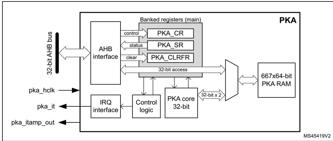
The diagram illustrates the internal architecture of the PKA. On the left, a 32-bit AHB bus connects to an AHB interface. The AHB interface is connected to three banked registers: PKA_CR (control), PKA_SR (status), and PKA_CLRFR (clear). A 32-bit access bus connects these registers to a 667x64-bit PKA RAM. Below the registers, an IRQ interface connects to control logic, which in turn connects to a PKA core 32-bit. The PKA core is connected to the 32-bit access bus via a 32-bit x 2 interface. External signals include pka_hclk (input), pka_it (output), and pka_itamp_out (output). The diagram is labeled MS45419V2.
29.3.2 PKA internal signals
Table 226 lists the internal signals available at the PKA level, not necessarily available on product bonding pads.
Table 226. Internal input/output signals
| Signal name | Signal type | Description |
|---|---|---|
| pka_hclk | Digital input | AHB bus clock |
| pka_it | Digital output | Public key accelerator IP global interrupt request |
| pka_itamp_out | Digital output | PKA internal tamper event signal to TAMP (XOR-ed), triggered when an unexpected fault occurs while PKA manipulates secrets, or when the programmed input point is not found on the input curve (ECDSA signature and ECC scalar multiplication only). This signal is asserted as soon as a fault is detected. When asserted, read access to PKA registers are reset to 0 and writes are ignored. The signal is de-asserted when PKA memory is cleared. |
29.3.3 PKA reset and clocks
PKA is clocked on the AHB bus clock. When the PKA peripheral reset signal is released PKA_RAM is cleared automatically, taking 667 clock cycles. During this time the setting of bit EN in PKA_CR register is ignored. Once EN bit is set, refer to Section 29.3.6 for details about PKA initialization sequence.
According to the security policy applied to the device, PKA RAM can also be reset following a tamper event. Refer to Tamper detection and response in the System security section (if applicable to this product).
29.3.4 PKA public key acceleration
Overview
Public key accelerator (PKA) is used to accelerate Rivest, Shamir and Adleman (RSA), Diffie-Hellman (DH) as well as ECC over prime field operations. Supported operand sizes is up to 4160 bits for RSA and DH, and up to 640 bits for ECC.
The PKA supports all non-singular elliptic curves defined over prime fields, that can be described with a short Weierstrass equation \( y^2 = x^3 + ax + b \pmod{p} \) . More information can be found in Section 29.5.1 .
Note: Binary curves, Edwards curves and Curve25519 are not supported by the PKA.
A memory of 5336 bytes (667 words of 64 bits) called PKA RAM is used to provide initial data to the PKA, and to hold the results after computation is completed. Access is done through the PKA AHB interface.
PKA operating modes
The list of operations the PKA can perform is detailed in Table 227 and Table 228 , respectively, for integer arithmetic functions and prime field (Fp) elliptic curve functions.
Table 227. PKA integer arithmetic functions list
| PKA_CR.MODE[5:0] | Performed operation | Reference | |
|---|---|---|---|
| Hex | Binary | ||
| 0x01 | 000001 | Montgomery parameter computation \( R^2 \bmod n \) | Section 29.4.2 |
| 0x0E | 001110 | Modular addition \( (A+B) \bmod n \) | Section 29.4.3 |
| 0x0F | 001111 | Modular subtraction \( (A-B) \bmod n \) | Section 29.4.4 |
| 0x10 | 010000 | Montgomery multiplication \( (AxB) \bmod n \) | Section 29.4.5 |
| 0x00 | 000000 | Modular exponentiation \( A^e \bmod n \) | Section 29.4.6 |
| 0x02 | 000010 | Modular exponentiation \( A^e \bmod n \) (fast mode) | |
| 0x03 | 000011 | Modular exponentiation \( A^e \bmod n \) (protected) | Section 29.4.6 |
| 0x08 | 001000 | Modular inversion \( A^{-1} \bmod n \) | Section 29.4.7 |
| 0x0D | 001101 | Modular reduction \( A \bmod n \) | Section 29.4.8 |
| 0x09 | 001001 | Arithmetic addition \( A+B \) | Section 29.4.9 |
| 0x0A | 001010 | Arithmetic subtraction \( A-B \) | Section 29.4.10 |
| 0x0B | 001011 | Arithmetic multiplication \( AxB \) | Section 29.4.11 |
| 0x0C | 001100 | Arithmetic comparison ( \( A=B, A>B, A<B \) ) | Section 29.4.12 |
| 0x07 | 000111 | RSA CRT exponentiation | Section 29.4.13 |
Table 228. PKA prime field (Fp) elliptic curve functions list
| PKA_CR.MODE[5:0] | Performed operation | Reference | |
|---|---|---|---|
| Hex | Binary | ||
| 0x28 | 101000 | Point on elliptic curve Fp check | Section 29.4.14 |
| 0x20 | 100000 | ECC scalar multiplication kP (protected) | Section 29.4.15 |
| 0x23 | 100011 | ECC complete addition | Section 29.4.18 |
| 0x24 | 100100 | ECDSA sign (protected) | Section 29.4.16 |
| 0x26 | 100110 | ECDSA verification | Section 29.4.17 |
| 0x27 | 100111 | ECC double base ladder | Section 29.4.19 |
| 0x2F | 101111 | ECC projective to affine | Section 29.4.20 |
Each of these operating modes has an associated code that has to be written to the MODE[5:0] bitfield in the PKA_CR register. If the application selects any value that is not documented below the write to MODE[5:0] bitfield is ignored, and an operation error (OPERRF) is triggered. When this happens, a new operation must be selected after the error is cleared.
Some operations in Table 227 and Table 228 are indicated as protected. Those operations are used when manipulating secret keys (modular exponentiation for RSA decryption, scalar multiplication and signature for ECC). Those secrets (protected against side channel attacks) and any intermediate values are automatically erased when PKA RAM is cleared at the end of the protected operations (BUSY goes low). They are also protected against side channel attacks.
Caution: For security reason it is very important to select protected modular exponentiation (MODE[5:0] = 0x3) when performing RSA decryption.
Montgomery space and fast mode operations
For efficiency reasons, the PKA internally performs modular multiply operations in the Montgomery domain, automatically performing inward and outward transformations.
As Montgomery parameter computation is time consuming, the application can decide to use a faster mode of operation during which the precomputed Montgomery parameter is supplied before starting the operation. The performance improvement is detailed in Section 29.5.2: Computation times .
The only operation using fast mode is the modular exponentiation (MODE[5:0] = 0x02).
29.3.5 Typical applications for PKA
Introduction
The PKA can be used to accelerate a number of public key cryptographic functions such as:
- • RSA encryption and decryption
- • RSA key finalization
- • CRT-RSA decryption
- • DSA and ECDSA signature generation and verification
- • DH and ECDH key agreement
The following publications specify the listed functions:
- • FIPS PUB 186-4, Digital Signature Standard (DSS), July 2013 by NIST
- • PKCS #1, RSA Cryptography Standard, v1.5, v2.1 and v2.2. by RSA Laboratories
- • IEEE1363-2000, IEEE Standard Specifications for Public-Key Cryptography, January 2000
- • ANSI X9.62-2005, Public Key Cryptography for the Financial Services Industry, The Elliptic Curve Digital Signature Algorithm (ECDSA), November 2005
Refer to these documents for full details. This document limits itself to describing principles.
RSA key pair
For the following RSA operations, a public key and a private key information are defined as follows:
- • Alice transmits her public key \( (n, e) \) to Bob. Numbers \( n \) and \( e \) are very large positive integers.
- • Alice keeps secret her private key \( d \) , also a very large positive integer. Alternatively, this private key can also be represented by a quintuple \( (p, q, dp, dq, qInv) \) .
For more information, refer to the RSA specification.
RSA encryption/decryption principle
As recommended by the PKCS#1 specification, Bob, to encrypt message \( M \) using Alice's public key \( (n, e) \) , must go through the following steps:
- 1. Compute the encoded message \( EM = \text{ENCODE}(M) \) , where ENCODE is an encoding method.
- 2. Turn \( EM \) into an integer \( m \) , with \( 0 \leq m < n \) and \( (m, n) \) being coprimes.
- 3. Compute ciphertext \( c = m^e \bmod n \) .
- 4. Convert the integer \( c \) into a string ciphertext \( C \) .
Alice, to decrypt ciphertext \( c \) using her private key \( d \) , follows the steps indicated below:
- 1. Convert the ciphertext \( C \) to an integer ciphertext representative \( c \) .
- 2. If necessary, retrieve the prime factors ( \( p \) , \( q \) ) using ( \( n \) , \( e \) , \( d \) ) information, then compute \( \phi = (p - 1) \times (q - 1) \) . Refer to NIST SP800-56B Appendix C for details.
- 3. Recover plaintext
\(
m = c^d \bmod n = (m^e)^d \bmod n
\)
. If the private key is the quintuple (
\(
p
\)
,
\(
q
\)
,
\(
dp
\)
,
\(
dq
\)
,
\(
qInv
\)
), then plaintext
\(
m
\)
is obtained by performing the operations:
- a) \( m_1 = c^{dp} \bmod p \)
- b) \( m_2 = c^{dq} \bmod q \)
- c) \( h = qInv (m_1 - m_2) \bmod p \)
- d) \( m = m_2 + h q \)
- 4. Convert the integer message representative \( m \) to an encoded message EM.
- 5. Recover message \( M = \text{DECODE}(\text{EM}) \) , where \( \text{DECODE} \) is a decoding method.
To accelerate these operations with the PKA, use Modular exponentiation \( A^e \bmod n \) if the private key is \( d \) , or RSA CRT exponentiation if the private key is the quintuple ( \( p \) , \( q \) , \( dp \) , \( dq \) , \( qInv \) ).
Note: The decoding operation and the conversion operations between message and integers are specified in PKCS#1 standard.
For the decryption process, the protected version of modular exponentiation (MODE[5:0] = 0x3) is strongly recommended for security reason. For the encryption process, the MODE[5:0] = 0x3 setting cannot be used as it requires the knowledge of the private key.
Elliptic curve selection
For the following ECC operations, the curve parameters are defined as follows:
- • Curve corresponds to the elliptic curve field agreed among actors (Alice and Bob). Supported curves parameters are summarized in Section 29.5.1: Supported elliptic curves .
- • \( G \) is the chosen elliptic curve base point (also known as generator), with a large prime order \( n \) (that is, \( n \times G = \text{identity element } O \) ).
ECDSA message signature generation
This section describes the ECDSA (elliptic curve digital signature algorithm) signature generation function principle.
Alice, to sign a message \( m \) using her private key integer \( d_A \) , goes through the following steps:
- 1. Calculate \( e = \text{HASH}(m) \) , where \( \text{HASH} \) is a cryptographic hash function.
- 2. Let \( z \) be the \( L_n \) leftmost bits of \( e \) , where \( L_n \) is the bit length of the group order \( n \) .
- 3. Select a cryptographically secure random integer \( k \) where \( 0 < k < n \) .
- 4. Calculate the curve point \( (x_1, y_1) = k \times G \) .
- 5. Calculate \( r = x_1 \bmod n \) . If \( r = 0 \) go back to step 3.
- 6. Calculate \( s = k^{-1} (z + r d_A) \bmod n \) . If \( s = 0 \) go back to step 3.
- 7. The signature is the pair \( (r, s) \) .
The PKA accelerates the steps 4. to 7. by using:
- • ECDsa sign , or
- • All of the following operations:
- – ECC Fp scalar multiplication \( k \times P \)
- – Modular reduction \( A \bmod n \)
- – Modular inversion \( A^{-1} \bmod n \)
- – Modular addition and Modular and Montgomery multiplication
ECDsa signature verification
This section describes the ECDsa (elliptic curve digital signature algorithm) signature verification function principle.
Bob, to authenticate Alice's signature, must have a copy of her public key curve point \( Q_A \) . Bob can verify that \( Q_A \) is a valid curve point by going through the following steps:
- 1. Check that \( Q_A \) is not equal to the identity element \( O \)
- 2. Check that \( Q_A \) is on the agreed curve
- 3. Check that \( n \times Q_A = O \) .
Then Bob executes the following procedure:
- 1. Verify that \( r \) and \( s \) are integer in \( [1, n-1] \)
- 2. Calculate \( e = \text{HASH}(m) \) , where \( \text{HASH} \) is the agreed cryptographic hash function
- 3. Let \( z \) be the \( L_n \) leftmost bits of \( e \)
- 4. Calculate \( w = s^{-1} \bmod n \)
- 5. Calculate \( u_1 = zw \bmod n \) and \( u_2 = rw \bmod n \)
- 6. Calculate the curve point \( (x_1, y_1) = u_1 \times G + u_2 \times Q_A \)
- 7. The signature is valid if \( r = x_1 \bmod n \) , it is invalid otherwise.
The PKA accelerates the steps 4. to 7. by using ECDsa verification .
29.3.6 PKA procedure to perform an operation
Enabling/disabling PKA
Setting the EN bit in the PKA_CR register enables the PKA peripheral. The PKA becomes available when the INITOK bit is set in the PKA_SR register. When EN = 0, the PKA peripheral is kept under reset, with its memory still accessible by the application through the AHB interface.
Note: When the PKA is in the process of clearing its memory, the EN bit cannot be set. When setting the EN bit in PKA_CR, make sure that the MODE[5:0] bitfield value corresponds to an authorized PKA operation (see OPERRF in Section 29.3.7).
Clearing the EN bit while a calculation is in progress aborts the operation. In this case, the content of the PKA memory is not guaranteed, with the exception of the PKA modes 0x03, 0x20 and 0x24. For these operations, the PKA memory is cleared after abort, making the memory unavailable for 667 cycles. During this clearing time only the PKA registers can be accessed, with writes to EN bits ignored.
If the INITOK bit stays at 0, make sure that the RNG peripheral is clocked and properly initialized, then try to enable the PKA again.
Data formats
The format of the input data and the results in the PKA RAM are specified, for each operation, in Section 29.4 .
Executing a PKA operation
To execute any of the supported PKA operations, proceed as follows:
- 1. Load initial data into the PKA internal RAM, which is located at address offset 0x400.
- 2. Write in the MODE[5:0] bitfield of PKA_CR register, specifying the operation which is to be executed and then assert the START bit, also in PKA_CR register.
- 3. Wait until the PROCENDF bit in the PKA_SR register is set, indicating that the computation is complete.
- 4. Read the result data from the PKA internal RAM, then clear PROCENDF bit by setting PROCENDFC bit in PKA_CLRFR.
Note: When PKA is busy (BUSY = 1), any access by the application to PKA RAM is ignored, and the RAMERRF flag is set in PKA_SR.
Selecting an illegal or unknown operation in step 2 triggers an OPERRF error and prevents the PROCENDF flag from being set and the procedure step 3 from being completed. See Section 29.3.7 for details.
Using precomputed Montgomery parameters (PKA fast mode)
As explained in Section 29.3.4 , when computing many operations with the same modulus, it can be beneficial for the application to compute the corresponding Montgomery parameter only once (see, for example, Section 29.4.5 ). This is referred to as fast mode .
To use the PKA peripheral in fast mode, follow this recommended procedure:
- 1. Load the modulus size and value information into the PKA RAM. Refer to Section 29.5.1 for detail.
- 2. Configure the PKA_CR register to Montgomery parameter computation mode (MODE[5:0] = 0x1), then assert the START bit.
- 3. Wait until the PROCENDF bit in the PKA_SR register is set. Then, read the corresponding Montgomery parameter from the PKA memory and clear the PROCENDF bit by setting PROCENDFC in PKA_CLRFR.
- 4. Continue with the required PKA operation, loading the Montgomery information R2 mod \( m \) on top of the regular input data. Relevant addresses are provided in Section 29.4 .
29.3.7 PKA error management
The following error flags in the PKA_SR register are set to indicate errors that may occur when using the PKA:
- • ADDRERRF flags that the access to PKA RAM falls outside the expected range.
- • RAMERRF flags an AHB access to the PKA RAM occurring while the PKA core uses the PKA RAM. While the flag is set, reads from the PKA RAM return 0 and writes are ignored.
- • OPERRF flags that the selected operating mode using MODE[5:0] bitfield is not listed in PKA operating modes (see the bitfield description), or PKA is running in limited mode
(see LMF bit in PKA_SR). While the flag is set, writes to the MODE[5:0] bitfield are ignored.
For each error flag, the PKA generates an interrupt if enabled with the corresponding bit in the PKA_CR register (see Section 29.7 for details).
The ADDRERRF, OPERRF, and RAMERRF error flags are cleared by setting the ADDRERRFC, OPERRFC, and RAMERRFC bit in PKA_CLRFR, respectively. The OPERRF error flag must be cleared before a new operation is initiated via the PKA_CR register.
Note: The PKA can be re-initialized at any moment by clearing the EN bit in the PKA_CR register.
29.4 PKA operating modes
29.4.1 Introduction
The operations supported by the PKA are detailed in the following subsections, which define the format of both input data and results stored in the PKA RAM.
Warning: Before starting any operation, ensure that all input parameters to the PKA are valid and consistent, as the PKA assumes their correctness. Additionally, input parameters must not exceed the operand sizes specified in the operation tables.
The following information applies to all PKA operations:
- • The PKA core processes 64-bit words in its RAM. Accordingly, in the PKA section of this document, 'word' denotes a 64-bit unit.
- • When writing an element as input in the PKA RAM, append an additional 64-bit word of zeros after the most significant word, except when the operand size is fixed at one word.
- • All RAM storage addresses refer to the least significant word of the data. To obtain the actual address, the application must add the base address of the PKA to the indicated offset.
- • Supported operand sizes are:
- – ROS (RSA operand size) : Data size is calculated as \( (\text{rsa\_size} / 64) + 1 \) words, where rsa_size is the modulus length in bits. For example, a 1024-bit RSA operand corresponds to 17 words (1088 bits).
- – EOS (ECC operand size) : Data size is \( (\text{ecc\_size} / 64) + 1 \) words, where ecc_size is the prime modulus length in bits. For example, a 192-bit ECC operand corresponds to four words (256 bits).
Note: Both ROS and EOS include the additional zero word.
- • Unless indicated otherwise, all operands in the tables are integers.
Note: Any fractional results in the formulas must be rounded to the nearest integer, as the PKA core processes data in 64-bit words.
Note: The maximum ROS is 66 words (4160-bit maximum exponent size), while the maximum EOS is 11 words (640-bit max operand size).
Example 1: Understanding endianness in PKA memory during ECC Fp scalar multiplication preparation
Write the x-coordinate of point P for an ECC P256 curve (EOS = 5 words) by placing the least significant bit at bit 0 of the word at address offset 0x578, and the most significant bit at bit 63 of the word at address offset 0x590. Then, write a zero word (0x0000000000000000) at address offset 0x598.
Example 2: Writing the curve coefficient 'a' for ECC Fp scalar multiplication
To write the value \( a = -3 \) for a curve with a modulus length of 224 bits (rounded up to five 64-bit words), write the PKA memory with data as in the following table:
Table 229. Example of 'a' curve coefficient for ECC Fp scalar
| RAM offset | Value | Note |
|---|---|---|
| 0x410 | 0x0000000000000001 | Curve coefficient a sign without extra word |
| 0x418 | 0x0000000000000011 | Value of \( |a| \) LSB |
| 0x420 | 0x0000000000000000 | - |
| 0x428 | 0x0000000000000000 | - |
| 0x430 | 0x0000000000000000 | Value of \( |a| \) MSB |
| 0x438 | 0x0000000000000000 | Additional zero word |
29.4.2 Montgomery parameter computation
This function is used to compute the Montgomery parameter ( \( R^2 \bmod n \) ) used by the PKA to convert operands into the Montgomery residue system representation. This operation can be very useful for fast mode operation because passing the Montgomery parameter as input saves the time for its computation.
Note: This operation also supports ECC curves when specifying the prime modulus length and EOS size.
The following table summarizes operation instructions for Montgomery parameter computation.
Table 230. Montgomery parameter computation
| Parameters with direction | Value (note) | Storage | Size | |
|---|---|---|---|---|
| IN | MODE[5:0] | 0x01 | PKA_CR | 6 bits |
| Modulus length | (in bits, \( 0 \leq \text{value} < 4160 \) ) | RAM@0x408 | 64 bits | |
| Modulus value \( n \) | (odd integer only, \( n < 2^{4160} \) ) | RAM@0x1088 | ROS | |
| OUT | Result: \( R^2 \bmod n \) | - | RAM@0x620 | |
29.4.3 Modular addition
The following table summarizes operation instructions for modular addition operation that calculates \( A + B \bmod n \) .
Table 231. Modular addition
| Parameters with direction | Value (note) | Storage | Size | |
|---|---|---|---|---|
| IN | MODE[5:0] | 0x0E | PKA_CR | 6 bits |
| Operand length | (in bits, not null) | RAM@0x408 | 64 bits | |
| Operand A | \( (0 \leq A < n) \) | RAM@0xA50 | ROS | |
| Operand B | \( (0 \leq B < n) \) | RAM@0xC68 | ||
| Modulus value \( n \) | \( (n < 2^{4160}) \) | RAM@0x1088 | ||
| OUT | Result: \( A + B \bmod n \) | \( (0 \leq \text{result} < n) \) | RAM@0xE78 | |
29.4.4 Modular subtraction
Modular subtraction operation calculates:
- • \( A - B \bmod n \) , when \( A \geq B \)
- • \( A + n - B \bmod n \) , when \( A < B \)
The following table summarizes the operation instructions.
Table 232. Modular subtraction
| Parameters with direction | Value (note) | Storage | Size | |
|---|---|---|---|---|
| IN | MODE[5:0] | 0x0F | PKA_CR | 6 bits |
| Operand length | (in bits, not null) | RAM@0x408 | 64 bits | |
| Operand A | \( (0 \leq A < n) \) | RAM@0xA50 | ROS | |
| Operand B | \( (0 \leq B < n) \) | RAM@0xC68 | ||
| Modulus value \( n \) | \( (n < 2^{4160}) \) | RAM@0x1088 | ||
| OUT | Result: \( A - B \bmod n \) | \( (0 \leq \text{result} < n) \) | RAM@0xE78 | |
29.4.5 Modular and Montgomery multiplication
To be more efficient when performing a sequence of multiplications, the PKA accelerates a multiplication that has at least one input in the Montgomery domain. The two main uses of this operation are:
- • Map a value from natural domain to Montgomery domain and vice-versa
- • Perform a modular multiplication \( A \times B \bmod n \)
The method to perform these operations is described next. The \( x \) function is this operation, and the \( A \) , \( B \) , and \( C \) operands are in the natural domain.
- 1. Inward or outward conversion to or from the Montgomery domain
- a) Assuming that
\(
A
\)
is an integer in the natural domain:
- – Compute \( r2modn \) using Montgomery parameter computation .
- – The result of \( AR = A \times r2modn \bmod n \) is \( A \) in the Montgomery domain.
- b) Assuming that
\(
BR
\)
is an integer in the Montgomery domain:
- – The result of \( B = BR \times 1 \bmod n \) is \( B \) in the natural domain.
- – Similarly, the \( AR \) value computed in a) can be converted into the natural domain by computing \( A = AR \times 1 \bmod n \) .
- a) Assuming that
\(
A
\)
is an integer in the natural domain:
- 2. Simple modular multiplication
\(
A \times B \bmod n
\)
- a) Compute \( r2modn \) using Montgomery parameter computation .
- b) Compute \( AR = A \times r2modn \bmod n \) . The output is in the Montgomery domain.
- c) Compute \( AB = AR \times B \bmod n \) . The output is in the natural domain.
- 3. Multiple modular multiplication
\(
A \times B \times C \bmod n
\)
- a) Compute \( r2modn \) using Montgomery parameter computation .
- b) Compute \( AR = A \times r2modn \bmod n \) . The output is in the Montgomery domain.
- c) Compute \( BR = B \times r2modn \bmod n \) . The output is in the Montgomery domain.
- d) Compute \( ABR = AR \times BR \bmod n \) . The output is in the Montgomery domain.
- e) Compute \( CR = C \times r2modn \bmod n \) . The output is in the Montgomery domain.
- f) Compute \( ABCR = ABR \times CR \bmod n \) . The output is in the Montgomery domain.
- g) (optional) Repeat the two previous steps if multiplying with additional operands is required.
- h) Compute \( ABC = ABCR \times 1 \bmod n \) to retrieve the result in the natural domain.
The following table summarizes the operation instructions.
Table 233. Montgomery multiplication
| Parameters with direction | Value (note) | Storage | Size | |
|---|---|---|---|---|
| IN | MODE[5:0] | 0x10 | PKA_CR | 6 bits |
| Operand length | (in bits, not null) | RAM@0x408 | 64 bits | |
| Operand A | \( (0 \leq A < n) \) | RAM@0xA50 | ROS | |
| Operand B | \( (0 \leq B < n) \) | RAM@0xC68 | ||
| Modulus value \( n \) | (odd integer only, \( n < 2^{4160} \) ) | RAM@0x1088 | ||
| OUT | Result: \( A \times B \bmod n^{(1)} \) | - | RAM@0xE78 | |
- 1. Result in Montgomery domain or in natural domain, depending upon the inputs nature (see examples 2 and 3).
29.4.6 Modular exponentiation
Modular exponentiation operation is commonly used to perform a single-step RSA operation. It calculates of \( A^e \bmod n \) .
RSA operation involving public information (RSA encryption) can use the normal or fast mode detailed on Table 234 and Table 235 . RSA operation involving secret information (RSA decryption) must use the protected mode detailed on Table 236 , for security reason.
Note: Once this operation is started PKA control register and PKA memory is no more available. Access is restored once BUSY bit is set to 0 by the PKA.
When this operation completes with errors due to unexpected hardware events a PKA tamper event is triggered to TAMP peripheral, and access to PKA RAM becomes blocked until erased by hardware.
Note: When \( MODE[5:0] = 0x03 \) , the error code is not affected when PKA automatically clears the PKA RAM at the end of this protected operation. When the error output equals \( 0xD60D \) , the result output is not affected either.
Operation instructions for modular exponentiation are summarized in Table 234 (normal mode), Table 235 (fast mode), and Table 236 (protected mode). Fast mode usage is explained in Section 29.3.6 .
Table 234. Modular exponentiation (normal mode)
| Parameters with direction | Value (note) | Storage | Size | |
|---|---|---|---|---|
| IN | MODE[5:0] | 0x00 | PKA_CR | 6 bits |
| IN | Exponent length | (in bits, not null) | RAM@0x400 | 64 bits |
| Operand length | (in bits, not null) | RAM@0x408 | ||
| IN/OUT | Operand A (base of exponentiation) | \( (0 \leq A < n) \) | RAM@0xC68 | |
| IN | Exponent e | \( (0 \leq e < n) \) | RAM@0xE78 | ROS |
| Modulus value n | (odd integer only, \( n < 2^{4160} \) ) | RAM@0x1088 | ||
| OUT | Result: \( A^e \bmod n \) | \( (0 \leq result < n) \) | RAM@0x838 | |
Table 235. Modular exponentiation (fast mode)
| Parameters with direction | Value (note) | Storage | Size | |
|---|---|---|---|---|
| IN | MODE[5:0] | 0x02 | PKA_CR | 6 bits |
| IN | Exponent length | (in bits, not null) | RAM@0x400 | 64 bits |
| Operand length | (in bits, not null) | RAM@0x408 | ||
| IN/OUT | Operand A (base of exponentiation) | \( (0 \leq A < n) \) | RAM@0xC68 | |
| IN | Exponent e | \( (0 \leq e < n) \) | RAM@0xE78 | ROS |
| Modulus value n | (odd integer only, \( n < 2^{4160} \) ) | RAM@0x1088 | ||
| IN/OUT | Montgomery parameter \( R^2 \bmod n \) | (mandatory) | RAM@0x620 | |
| OUT | Result: \( A^e \bmod n \) | \( (0 \leq result < n) \) | RAM@0x838 | |
Table 236. Modular exponentiation (protected mode)
| Parameters with direction | Value (note) | Storage | Size | |
|---|---|---|---|---|
| IN | MODE[5:0] | 0x03 | PKA_CR | 6 bits |
| Exponent \( e \) length | (in bits, not null) | RAM@0x400 | 64 bits | |
| Modulus or operand length | (in bits, not null) | RAM@0x408 | ||
| Operand \( A \) (base of exponentiation) | ( \( 0 \leq A < n \) ) | RAM@0x16C8 | ROS | |
| Exponent \( e \) | ( \( 0 \leq e < n \) ) | RAM@0x14B8 | ||
| Modulus value \( n \) | (odd integer only, \( n < 2^{4096} \) ) | RAM@0x0838 | ||
| Phi value (1) | - | RAM@0x0C68 | ||
| OUT | Result: \( A^e \bmod n \) | ( \( 0 \leq \text{result} < n \) ) | RAM@0x838 | |
| ERROR | Error \( A^e \bmod n \) | No errors: 0xD60D Errors: 0xCBC9 | RAM@0x1298 | 64 bits |
- 1. Euler totient function of \( n^1 \) with \( \phi = (p - 1) \times (q - 1) \) , where \( p \) and \( q \) are prime factors of modulus \( n \) (see NIST SP800-56B Appendix C or RSA encryption/decryption principle for details). As optimization it is recommended to keep \( \phi \) information as part of the key pair generation. Alternative is to store the key as \( (p, q, e, d) \) instead of \( (N, e, d, \phi) \) , in this case, to derive \( N \) and \( \phi \) using PKA arithmetic multiplier: \( N = p \times q \) , and \( \phi = (p - 1) \times (q - 1) \) .
29.4.7 Modular inversion
The modular inversion operation calculates multiplicative inverse \( A^{-1} \bmod n \) . If the modulus \( n \) is prime, for all values of \( A \) ( \( 1 \leq A < n \) ) modular inversion output is valid. If the modulus \( n \) is not prime, \( A \) has an inverse only if the greatest common divisor between \( A \) and \( n \) is 1.
If the operand \( A \) is a divisor of the modulus \( n \) the result is a multiple of a factor of \( n \) .
The following table summarizes the operation instructions.
Table 237. Modular inversion
| Parameters with direction | Value (note) | Storage | Size | |
|---|---|---|---|---|
| IN | MODE[5:0] | 0x08 | PKA_CR | 6 bits |
| Operand length | (in bits, not null) | RAM@0x408 | 64 bits | |
| Operand \( A \) | ( \( 0 \leq A < n \) ) | RAM@0xA50 | ROS | |
| Modulus value \( n \) | (odd integer only, \( n < 2^{4160} \) ) | RAM@0xC68 | ||
| OUT | Result: \( A^{-1} \bmod n \) | \( 0 < \text{result} < n \) | RAM@0xE78 | |
29.4.8 Modular reduction
The modular reduction operation calculates the remainder of \( A \) divided by \( n \) .
The following table summarizes the operation instructions.
Table 238. Modular reduction
| Parameters with direction | Value (note) | Storage | Size | |
|---|---|---|---|---|
| IN | MODE[5:0] | 0x0D | PKA_CR | 6 bits |
| Operand length | (in bits, not null) | RAM@0x400 | 64 bits | |
| Modulus length | (in bits, \( 8 < \text{value} < 4160 \) ) | RAM@0x408 | ||
| Operand A | ( \( 0 \leq A < 2n < 2^{4160} \) ) | RAM@0xA50 | ROS | |
| Modulus value \( n \) | (odd integer only, \( n < 2^{4160} \) ) | RAM@0xC68 | ||
| OUT | Result \( A \bmod n \) | ( \( 0 < \text{result} < n \) ) | RAM@0xE78 | |
29.4.9 Arithmetic addition
The arithmetic addition operation calculates \( A + B \) .
The following table summarizes the operation instructions.
Table 239. Arithmetic addition
| Parameters with direction | Value (note) | Storage | Size | |
|---|---|---|---|---|
| IN | MODE[5:0] | 0x09 | PKA_CR | 6 bits |
| Operand length \( M \) | (in bits, not null) | RAM@0x408 | 64 bits | |
| Operand A | ( \( 0 \leq A < 2^M \) ) | RAM@0xA50 | ROS | |
| Operand B | ( \( 0 \leq B < 2^M \) ) | RAM@0xC68 | ||
| OUT | Result: \( A + B \) | ( \( 0 \leq \text{result} < 2^{M+1} \) ) | RAM@0xE78 | ROS + 1 |
29.4.10 Arithmetic subtraction
The arithmetic subtraction operation calculates:
- • \( A - B \) , when \( A \geq B \)
- • \( A + 2^{\text{int}(M/32) \times 32 + 1} - B \) , when \( A < B \) and the residue of \( M/32 \) is greater than zero
- • \( A + 2^{\text{int}(M/32) \times 32} - B \) , when \( A < B \) and the residue of \( M/32 \) is zero
For the last two list items, the 32-bit word following the most significant word of the output is 0xFFFF FFFF, as the result is negative.
The following table summarizes the operation instructions.
Table 240. Arithmetic subtraction
| Parameters with direction | Value (note) | Storage | Size | |
|---|---|---|---|---|
| IN | MODE[5:0] | 0x0A | PKA_CR | 6 bits |
| Operand length \( M \) | (in bits, not null) | RAM@0x408 | 64 bits | |
| Operand A | ( \( 0 \leq A < 2^M \) ) | RAM@0xA50 | ROS | |
| Operand B | ( \( 0 \leq B < 2^M \) ) | RAM@0xC68 | ||
| OUT | Result: \( A - B \) | ( \( 0 \leq \text{result} < 2^M \) ) | RAM@0xE78 | |
29.4.11 Arithmetic multiplication
The arithmetic multiplication operation calculates \( A \times B \) .
The following table summarizes the operation instructions.
Table 241. Arithmetic multiplication
| Parameters with direction | Value (note) | Storage | Size | |
|---|---|---|---|---|
| IN | MODE[5:0] | 0x0B | PKA_CR | 6 bits |
| Operand length \( M \) | (in bits, not null) | RAM@0x408 | 64 bits | |
| Operand \( A \) | \( (0 \leq A < 2^M) \) | RAM@0xA50 | ROS | |
| Operand \( B \) | \( (0 \leq B < 2^M) \) | RAM@0xC68 | ||
| OUT | Result: \( A \times B \) | \( (0 \leq \text{result} < 2^{2M}) \) | RAM@0xE78 | 2xROS |
29.4.12 Arithmetic comparison
The arithmetic comparison operation yields the following results:
- • 0xED2C , when \( A = B \)
- • 0x7AF8 , when \( A > B \)
- • 0x916A , when \( A < B \)
The following table summarizes the operation instructions.
Table 242. Arithmetic comparison
| Parameters with direction | Value (note) | Storage | Size | |
|---|---|---|---|---|
| IN | MODE[5:0] | 0x0C | PKA_CR | 6 bits |
| Operand length \( M \) | (in bits, not null) | RAM@0x408 | 64 bits | |
| Operand \( A \) | \( (0 \leq A < 2^M) \) | RAM@0xA50 | ROS | |
| Operand \( B \) | \( (0 \leq B < 2^M) \) | RAM@0xC68 | ||
| OUT | If result \( A = B \) | 0xED2C, 0x7AF8, or 0x916A | RAM@0xE78 | 64 bits |
29.4.13 RSA CRT exponentiation
For efficiency many popular crypto libraries such as OpenSSL RSA use the following optimization for decryption and signing based on the Chinese remainder theorem (CRT):
- • \( p \) and \( q \) are precomputed primes, stored as part of the private key
- • \( d_P = d \bmod (p - 1) \)
- • \( d_Q = d \bmod (q - 1) \) and
- • \( q_{inv} = q^{-1} \bmod p \)
These values allow the recipient to compute the exponentiation \( m = A^d \pmod{pq} \) more efficiently as follows:
- • \( m_1 = A^{d_P} \pmod{p} \)
- • \( m_2 = A^{d_Q} \pmod{q} \)
- • \( h = q_{inv} (m_1 - m_2) \pmod{p} \) , with \( m_1 > m_2 \)
- • \( m = m_2 + hq \pmod{pq} \)
Operation instructions for computing CRT exponentiation \( A^d \pmod{pq} \) are summarized in Table 243 .
Table 243. CRT exponentiation
| Parameters with direction | Value (note) | Storage | Size | |
|---|---|---|---|---|
| IN | MODE[5:0] | 0x07 | PKA_CR | 6 bits |
| IN | Operand length | (in bits, not null) | RAM@0x408 | 64 bits |
| IN | Operand \( d_P \) | \( (0 < d_P < 2^{M/2}) \) | RAM@0x730 | ROS / 2 |
| Operand \( d_Q \) | \( (0 < d_Q < 2^{M/2}) \) | RAM@0xE78 | ||
| Operand \( q_{inv} \) | \( (0 < q_{inv} < 2^{M/2}) \) | RAM@0x948 | ||
| Prime \( p^{(1)} \) | \( (0 < p < 2^{M/2}) \) | RAM@0xB60 | ||
| Prime \( q^{(1)} \) | \( (0 < q < 2^{M/2}) \) | RAM@0x1088 | ||
| IN | Operand A | \( (0 < A < 2^M) \) | RAM@0x12A0 | ROS |
| OUT | Result: \( A^d \pmod{pq} \) | \( (0 \leq \text{result} < pq) \) | RAM@0x838 | |
1. Must be different from 2.
29.4.14 Point on elliptic curve Fp check
This operation checks whether a given point \( P(x, y) \) satisfies or not the curves over prime fields equation \( y^2 = (x^3 + ax + b) \pmod{p} \) , where \( a \) and \( b \) are elements of the curve.
The following table summarizes the operation instructions.
Table 244. Point on elliptic curve\( F_p \) check| Parameters with direction | Value (note) | Storage | Size | |
|---|---|---|---|---|
| IN | MODE[5:0] | 0x28 | PKA_CR | 6 bits |
| Modulus length | (in bits, not null, \( 8 < \text{value} < 640 \) ) | RAM@0x408 | 64 bits | |
| Curve coefficient \( a \) sign | 0x0: positive 0x1: negative | RAM@0x410 | ||
| Curve coefficient \( |a| \) | (absolute value, \( |a| < p \) ) | RAM@0x418 | EOS | |
| Curve coefficient \( b \) | ( \( |b| < p \) ) | RAM@0x520 | ||
| Curve modulus value \( p \) | (odd integer prime, \( 0 < p < 2640 \) ) | RAM@0x470 | ||
| Point P coordinate \( x \) | ( \( x < p \) ) | RAM@0x578 | ||
| Point P coordinate \( y \) | ( \( y < p \) ) | RAM@0x5D0 | ||
| Montgomery parameter \( R^2 \bmod n \) | - | RAM@0x4C8 | ||
| OUT | Result: point \( P \) on curve | 0xD60D: point on curve 0xA3B7: point not on curve 0xF946: \( x \) or \( y \) coordinate is not smaller than modulus \( p \) | RAM@0x680 | 64 bits |
29.4.15 ECC \( F_p \) scalar multiplication
This operation calculates \( k \times P(x_P, y_P) \) , where \( P \) is a point on a curve over prime fields and \( x \) is the elliptic curve scalar point multiplication. The result is a point that belongs to the same curve or a point at infinity.
Note: Once this operation is started PKA control register and PKA memory is no more available. Access is restored once BUSY bit is set to 0 by the PKA.
When this operation completes with errors due to unexpected hardware events, a PKA tamper event is triggered to TAMP peripheral, and access to PKA RAM becomes blocked until erased by hardware. PKA tamper is also triggered when the programmed input point is not found on the input ECC curve. PKA operation point on elliptic curve can be used to avoid this.
The following table summarizes the operation instructions.
Table 245. ECC\( F_p \) scalar multiplication| Parameters with direction | Value (note) | Storage | Size | |
|---|---|---|---|---|
| IN | MODE[5:0] | 0x20 | PKA_CR | 6 bits |
| IN | Curve prime order \( n \) length | (in bits, not null,) | RAM@0x400 | 64 bits |
| Curve modulus \( p \) length | (in bits, not null, \( 8 < \text{value} < 640 \) ) | RAM@0x408 | ||
| Curve coefficient \( a \) sign | 0x0: positive 0x1: negative | RAM@0x410 | ||
Table 245. ECC Fp scalar multiplication (continued)
| Parameters with direction | Value (note) | Storage | Size | |
|---|---|---|---|---|
| IN | Curve coefficient \( |a| \) | (absolute value, \( |a| < p \) ) | RAM@0x418 | EOS |
| Curve coefficient \( b \) | (positive integer) | RAM@0x520 | ||
| Curve modulus value \( p \) | (odd integer prime, \( 0 < p < 2^{640} \) ) | RAM@0x1088 | ||
| Scalar multiplier \( k \) | ( \( 0 \leq k < n \) ) | RAM@0x12A0 | ||
| Point P coordinate \( x_P \) | ( \( x_P < p \) ) | RAM@0x578 | ||
| Point P coordinate \( y_P \) | ( \( y_P < p \) ) | RAM@0x470 | ||
| Curve prime order \( n \) | (integer prime) | RAM@0xF88 | ||
| OUT | Result: \( k \times P \) coordinate \( x' \) | (result \( < p \) ) | RAM@0x578 | EOS |
| Result: \( k \times P \) coordinate \( y' \) | (result \( < p \) ) | RAM@0x5D0 | ||
| ERROR | Error \( k \times P \) | No errors: 0xD60D Errors: 0xCBC9 | RAM@0x680 | 64 bits |
When performing this operation the following special cases must be noted:
- • For \( k = 0 \) this function returns a point at infinity \( (0, 0) \) if curve parameter \( b \) is nonzero, \( (0, 1) \) otherwise. For \( k \) different from 0 it might happen that a point at infinity is returned. When the application detects this behavior, a new computation must be carried out.
- • For \( k < 0 \) (that is, a negative scalar multiplication is required) the multiplier absolute value \( k = |k| \) must be provided to the PKA. After the computation completion, the formula \( P = (x, -y) \) can be used to compute the \( y \) coordinate of the effective final result (the \( x \) coordinate remains the same).
Note: The error code is not affected when PKA automatically clears the PKA RAM at the end of this protected operation. When the error output equals 0xD60D, the result output is not affected either.
29.4.16 ECDSA sign
Table 246 (input parameters) and Table 247 (output parameters) summarize the ECDSA signing operation.
Upon an output error different from 0xD60D, the application must generate a new \( k \) and repeat the ECDSA sign operation.
Note: As long as this operation is ongoing (BUSY = 1), the PKA control register and the PKA memory are not accessible. The access is restored when the PKA clears the BUSY bit.
The operation completion with errors due to unexpected hardware events triggers a PKA tamper event in the TAMP peripheral and blocks access to the PKA RAM until the hardware erases the event. Missing programmed input point on the input ECC curve also triggers a PKA tamper event. The use of the point on elliptic curve PKA operation prevents this.
Table 246. ECDSA sign - Inputs| Parameters with direction | Value (note) | Storage | Size | |
|---|---|---|---|---|
| IN | MODE[5:0] | 0x24 | PKA_CR | 6 bits |
| Curve prime order \( n \) length ( nlen ) | (in bits, not null) | RAM@0x400 | 64 bits | |
| Curve modulus \( p \) length | (in bits, \( 8 < \text{value} < 640 \) ) | RAM@0x408 | ||
| Curve coefficient \( a \) sign | 0x0: positive 0x1: negative | RAM@0x410 | ||
| Curve coefficient \( |a| \) | (absolute value, \( |a| < p \) ) | RAM@0x418 | EOS | |
| Curve coefficient \( b \) | (positive integer) | RAM@0x520 | ||
| Curve modulus value \( p \) | (odd integer prime, \( 0 < p < 2^{640} \) ) | RAM@0x1088 | ||
| Integer \( k^{(1)} \) | ( \( 0 \leq k < n \) ) | RAM@0x12A0 | ||
| Curve base point \( G \) coordinate \( x \) | ( \( x < p \) ) | RAM@0x578 | ||
| Curve base point \( G \) coordinate \( y \) | ( \( y < p \) ) | RAM@0x470 | ||
| Hash of message \( z \) | (hash size equal to nlen ) (2) | RAM@0xFE8 | ||
| Private key \( d \) | ( \( 0 < d \) ) | RAM@0xF28 | ||
| Curve prime order \( n \) | (integer prime) | RAM@0xF88 | ||
- 1. This integer is usually a cryptographically secure random number, but in some cases \( k \) can be deterministically generated.
- 2. To match the hash parameter size to the length of the curve prime order \( n \) , pad the result with zeros or use the hash truncation.
| Parameters with direction | Value (note) | Storage | Size | |
|---|---|---|---|---|
| OUT | Signature part \( r \) | ( \( 0 < r < n \) ) | RAM@0x730 | EOS |
| Signature part \( s \) | ( \( 0 < s < n \) ) | RAM@0x788 | ||
| ERROR | Result of signature | 0xD60D: successful computation, no error 0xCBC9: failed computation 0xA3B7: signature part \( r \) is equal to 0 0xF946: signature part \( s \) is equal to 0 | RAM@0xFE0 | 64 bits |
Note: The error code is not affected when the PKA automatically clears the PKA RAM at the end of this protected operation. The error output 0xD60D does not affect the result output either.
Extended ECDSA support
The PKA also supports the extended ECDSA signature, which accepts the same inputs as the standard ECDSA signature (see Table 246 ) and produces similar outputs (see Table 247 ), with the addition of the point \( kG \) coordinates. The following table defines these additional outputs.
Table 248. Extended ECDSA sign - additional outputs
| Parameters with direction | Value (note) | Storage | Size | |
|---|---|---|---|---|
| OUT | Curve point \( kG \) coordinate \( x_1 \) | \( (0 \leq x_1 < p) \) | RAM@0x1400 | EOS |
| Curve point \( kG \) coordinate \( y_1 \) | \( (0 \leq y_1 < p) \) | RAM@0x1458 | ||
29.4.17 ECDSA verification
Table 249 (input parameters) and Table 250 (output parameters) summarize the ECDSA verification operation.
Upon an output error different from 0xD60D, the signature is not verified.
Table 249. ECDSA verification - inputs
| Parameters with direction | Value (note) | Storage | Size | |
|---|---|---|---|---|
| IN | MODE[5:0] | 0x26 | PKA_CR | 6 bits |
| Curve prime order \( n \) length ( \( n/len \) ) | (in bits, not null) | RAM@0x408 | 64 bits | |
| Curve modulus \( p \) length | (in bits, not null, \( 8 < \text{value} < 640 \) ) | RAM@0x4C8 | ||
| Curve coefficient \( a \) sign | 0x0: positive 0x1: negative | RAM@0x468 | ||
| Curve coefficient \( |a| \) | (absolute value, \( |a| < p \) ) | RAM@0x470 | ||
| Curve modulus value \( p \) | (odd integer prime, \( 0 < p < 2^{640} \) ) | RAM@0x4D0 | EOS | |
| Curve base point \( G \) coordinate \( x \) | \( (x < p) \) | RAM@0x678 | ||
| Curve base point \( G \) coordinate \( y \) | \( (y < p) \) | RAM@0x6D0 | ||
| Public-key curve point \( Q \) coordinate \( x_Q \) | \( (x_Q < p) \) | RAM@0x12F8 | ||
| Public-key curve point \( Q \) coordinate \( y_Q \) | \( (y_Q < p) \) | RAM@0x1350 | ||
| Signature part \( r \) | \( (0 < r < n) \) | RAM@0x10E0 | ||
| Signature part \( s \) | \( (0 < s < n) \) | RAM@0xC68 | ||
| Hash of message \( z \) | (hash size equal to \( n/len \) ) (1) | RAM@0x13A8 | ||
| Curve prime order \( n \) | (integer prime) | RAM@0x1088 | ||
- 1. To match the hash parameter size to the length of the curve prime order \( n \) , pad the result with zeros or use the hash truncation.
| Parameters with direction | Value (note) | Storage | Size | |
|---|---|---|---|---|
| OUT | Result: ECDSA verify | – 0xD60D: valid signature – 0xA3B7: invalid signature | RAM@0x5D0 | 64 bits |
| Computed signature part \( r \) | – \( (0 < r < n) \) | RAM@0x578 | EOS | |
29.4.18 ECC complete addition
The ECC complete addition operation calculates the sum of two points on an elliptic curve. Operation instructions are summarized in Table 251 .
Note: The two input points and the resulting point are represented in Jacobian coordinates (X, Y, Z). To input a point in affine coordinates (x, y) conversion \( (X, Y, Z) = (x, y, 1) \) can be used. To convert resulting point to Jacobian coordinates conversion \( (x, y) = (X / Z^2, Y / Z^3) \) can be used.
Table 251. ECC complete addition| Parameters with direction | Value (note) | Storage | Size | |
|---|---|---|---|---|
| IN | MODE[5:0] | 0x23 | PKA_CR | 6 bits |
| Curve modulus \( p \) length | (in bits, not null, \( 8 < \text{value} < 640 \) ) | RAM@0x408 | 64 bits | |
| Curve coefficient \( a \) sign | – 0x0: positive 0x1: negative | RAM@0x410 | ||
| Curve modulus value \( p \) | (odd integer prime, \( 0 < p < 2^{640} \) ) | RAM@0x470 | EOS | |
| Curve coefficient \( |a| \) | (absolute value, \( |a| < p \) ) | RAM@0x418 | ||
| First point P coordinate X | \( (x < p) \) | RAM@0x628 | ||
| First point P coordinate Y | \( (y < p) \) | RAM@0x680 | ||
| First point P coordinate Z | \( (z < p) \) | RAM@0x6D8 | ||
| Second point Q coordinate X | \( (x < p) \) | RAM@0x730 | ||
| Second point Q coordinate Y | \( (y < p) \) | RAM@0x788 | ||
| Second point Q coordinate Z | \( (z < p) \) | RAM@0x7E0 | ||
| Result coordinate X | \( (x < p) \) | RAM@0xD60 | ||
| OUT | Result coordinate Y | \( (y < p) \) | RAM@0xDB8 | |
| Result coordinate Z | \( (z < p) \) | RAM@0xE10 | ||
29.4.19 ECC double base ladder
ECC double base ladder operation consists in the computation of \( k \times P + m \times Q \) , where \( (P, Q) \) are two points on an elliptic curve and \( (k, m) \) are two scalars. Operation instructions are summarized in Table 252 .
If the resulting point is the point at infinity (error code 0xA3B7), the resulting coordinate equals to (0, 0).
Note: The two input points are represented in Jacobian coordinates \( (X, Y, Z) \) . To input a point in affine coordinates \( (x, y) \) conversion \( (X, Y, Z) = (x, y, 1) \) can be used. The result is represented in affine coordinates \( (x, y) \) .
This operation requires the input point Z coordinate to be equal to 1 (input point represented in affine coordinates).
Table 252. ECC double base ladder
| Parameters with direction | Value (note) | Storage | Size | |
|---|---|---|---|---|
| IN | MODE[5:0] | 0x27 | PKA_CR | 6 bits |
| Curve prime order \( n \) length | (in bits, not null) | RAM@0x400 | 64 bits | |
| Curve modulus \( p \) length | (in bits, not null, \( 8 < \text{value} < 640 \) ) | RAM@0x408 | ||
| Curve coefficient \( a \) sign | – 0x0: positive – 0x1: negative | RAM@0x410 | EOS | |
| Curve coefficient \( |a| \) | (absolute value, \( |a| < p \) ) | RAM@0x418 | ||
| Curve modulus value \( p \) | (odd integer prime, \( 0 < p < 2^{640} \) ) | RAM@0x470 | ||
| Integer \( k \) | ( \( 0 < k < 2^{640} \) ) | RAM@0x520 | ||
| Integer \( m \) | ( \( 0 < m < 2^{640} \) ) | RAM@0x578 | ||
| First point \( P \) coordinate \( X \) | ( \( x < p \) ) | RAM@0x628 | ||
| First point \( P \) coordinate \( Y \) | ( \( y < p \) ) | RAM@0x680 | ||
| First point \( P \) coordinate \( Z \) | ( \( z < p \) ) | RAM@0x6D8 | ||
| Second point \( Q \) coordinate \( X \) | ( \( x < p \) ) | RAM@0x730 | ||
| Second point \( Q \) coordinate \( Y \) | ( \( y < p \) ) | RAM@0x788 | ||
| Second point \( Q \) coordinate \( Z \) | ( \( z < p \) ) | RAM@0x7E0 | ||
| Result coordinate \( x \) | ( \( x < p \) ) | RAM@0x578 | ||
| OUT | Result coordinate \( y \) | ( \( y < p \) ) | RAM@0x5D0 | EOS |
| Error code | – Point not at infinity: 0xD60D – Point at infinity: 0xA3B7 | RAM@0x520 | 64 bits | |
29.4.20 ECC projective to affine
ECC projective to affine operation calculates the conversion between the representation of a point \( P \) in homogeneous projective coordinates and the representation of the point \( P \) in affine coordinates. Namely, if the point is represented by the triple \( (X, Y, Z) \) , it calculates the affine coordinates \( (x, y) = (X / Z, Y / Z) \) .
All the operations are performed modulo the modulus \( p \) of the curve, which the point belongs to. If the resulting point is the point at infinity (error code 0xA3B7), resulting coordinate equals \( (0, 0) \) .
Operation instructions are summarized in Table 253 .
Table 253. ECC projective to affine
| Parameters with direction | Value (note) | Storage | Size | |
|---|---|---|---|---|
| IN | MODE[5:0] | 0x2F | PKA_CR | 6 bits |
| Curve modulus \( p \) length | (in bits, \( 8 < \text{value} < 640 \) ) | RAM@0x408 | 64 bits | |
| Curve modulus value \( p \) | (odd integer prime, \( 0 < p < 2^{640} \) ) | RAM@0x470 | EOS | |
| Point P coordinate \( X \) (projective) | ( \( x < p \) ) | RAM@0xD60 | ||
| Point P coordinate \( Y \) (projective) | ( \( y < p \) ) | RAM@0xDB8 | ||
| Point P coordinate \( Z \) (projective) | ( \( z < p \) ) | RAM@0xE10 | ||
| Montgomery parameter \( R^2 \bmod n \) | - | RAM@0x4C8 | ||
| OUT | Point P coordinate \( x \) (affine) | ( \( x < p \) ) | RAM@0x578 | |
| Point P coordinate \( y \) (affine) | ( \( y < p \) ) | RAM@0x5D0 | ||
| ERROR | Error code | Point not at infinity: 0xD60D Point at infinity: 0xA3B7 | RAM@0x680 | 64 bits |
29.5 Example of configurations and processing times
29.5.1 Supported elliptic curves
The PKA supports all non-singular elliptic curves defined over prime fields. Those curves can be described with a short Weierstrass equation, \( y^2 = x^3 + ax + b \pmod{p} \) .
Note: Binary curves, Edwards curves and Curve25519 are not supported by the PKA. The maximum supported operand size for ECC operations is 640 bits.
When publishing the ECC domain parameters of those elliptic curves, standard bodies define the following parameters:
- • the prime integer \( p \) , used as the modulus for all point arithmetic in the finite field \( GF(p) \)
- • the (usually prime) integer \( n \) , the order of the group generated by \( G \) , defined below
- • the base point of the curve \( G \) , defined by its coordinates ( \( G_x, G_y \) )
- • the integers \( a \) and \( b \) , coefficients of the short Weierstrass equation.
For the last bullet, when standard bodies define \( a \) as negative, PKA supports two representations:
- 1.
a defined as
\(
p-|a|
\)
in the finite field
\(
GF(p)
\)
, for example
\(
p-3
\)
:
Curve coefficient \( p = \text{0xFFFFFFFF FFFFFFFF FFFFFFFF FFFFFFFF FFFFFFFF 00000000 FFFFFFFF FFFFFFFF} \)
Curve coefficient \( a \) sign= 0x0 (positive)
Curve coefficient \( a = \text{0xFFFFFFFF FFFFFFFF FFFFFFFF FFFFFFFF FFFFFFFF 00000000 FFFFFFFF FFFFFFFC} \) - 2.
a defined as negative
, for example
-3
:
Curve coefficient \( p = \text{0xFFFFFFFF FFFFFFFF FFFFFFFF FFFFFFFF FFFFFFFF 00000000 FFFFFFFF FFFFFFFF} \)
Curve coefficient \( a \) sign= 0x1 (negative)
Curve coefficient \( a = \text{0x00000000 00000000 00000000 00000000 00000000 00000000 00000000 00000003} \)
Table 254 summarizes the family of curves supported by PKA for ECC operations.
Table 254. Family of supported curves for ECC operations
| Curve name | Standard | Reference | |
|---|---|---|---|
| P-192 | NIST | Digital Signature Standard (DSS) , NIST FIPS 186-4 | |
| P-224 | |||
| P-256 | |||
| P-384 | |||
| P-521 | |||
| brainpoolP224r1, brainpoolP224t1 | IETF |
| https://tools.ietf.org |
| brainpoolP256r1, brainpoolP256t1 | |||
| brainpoolP320r1, brainpoolP320t1 | |||
| brainpoolP384r1, brainpoolP384t1 | |||
| brainpoolP512r1, brainpoolP512t1 | |||
| secp192k1, secp192r1 | SEC | Standards for Efficient Cryptography SEC 2 curves | https://www.secg.org |
| secp224k1, secp224r1 | |||
| secp256k1, secp256r1 | |||
| secp384r1 | |||
| secp521r1 | |||
| Recommended curve parameters for public key cryptographic algorithm SM2 | OSCCA |
| |
29.5.2 Computation times
The following tables summarize the PKA computation times, expressed in AHB clock cycles.
Table 255. Modular exponentiation
| Exponent length (in bits) | Mode | Modulus length (in bits) | |||
|---|---|---|---|---|---|
| 1024 | 2048 | 3072 | 4096 | ||
| 3 | Normal | 124600 | 491000 | 684000 | 1133200 |
| Fast | 22700 | 82000 | 178000 | 311000 | |
| 17 | Normal | 135700 | 531400 | 772400 | 1288000 |
| Fast | 33800 | 122500 | 266500 | 465800 | |
| \( 2^{16} + 1 \) | Normal | 180000 | 693700 | 1126200 | 1907200 |
| Fast | 78200 | 284700 | 620400 | 1085000 | |
| 1024 | Protected | 9958000 | - | - | - |
| Normal | 5850000 | - | - | - | |
| Fast | 5748000 | - | - | - | |
| CRT (1) | 1775000 | - | - | - | |
| 2048 | Protected | - | 63886000 | - | - |
| Normal | - | 42240000 | - | - | |
| Fast | - | 41832000 | - | - | |
| CRT (1) | - | 11670000 | - | - | |
| 3072 | Protected | - | - | 199403000 | - |
| Normal | - | - | 136830000 | - | |
| Fast | - | - | 136325000 | - | |
| CRT (1) | - | - | 36886000 | - | |
| 4096 | Protected | - | - | - | 454318000 |
| Normal | - | - | - | 316000000 | |
| Fast | - | - | - | 315226000 | |
| CRT (1) | - | - | - | 84577000 | |
1. CRT stands for chinese remainder theorem optimization (MODE[5:0] bitfield= 0x07).
Table 256. ECC scalar multiplication (1)
| Modulus length (in bits) | |||||||
|---|---|---|---|---|---|---|---|
| 160 | 192 | 256 | 320 | 384 | 512 | 521 | 640 |
| - | 1590000 | 3083000 | 5339000 | 8518000 | 17818000 | 21053000 | 31826000 |
1. These times depend on the number of 1s included in the scalar parameter, and include the computation of Montgomery parameter R2.
Table 257. ECDSA signature average computation time (1) (2)| Modulus length (in bits) | |||||||
|---|---|---|---|---|---|---|---|
| 160 | 192 | 256 | 320 | 384 | 512 | 521 | 640 |
| - | 1500000 | 2744000 | 4579000 | 7184000 | 14455000 | 16685000 | 24965000 |
- 1. These values are average execution times of random moduli of given length, as they depend upon the length and the value of the modulus.
- 2. The execution time for the moduli that define the finite field of NIST elliptic curves is shorter than that needed for the moduli used for Brainpool elliptic curves or for random moduli of the same size.
| Modulus length (in bits) | |||||||
|---|---|---|---|---|---|---|---|
| 160 | 192 | 256 | 320 | 384 | 512 | 521 | 640 |
| 1011000 | 1495000 | 2938000 | 5014000 | 7979000 | 16804000 | 19254000 | 29582000 |
| Modulus length (in bits) | |||||||
|---|---|---|---|---|---|---|---|
| 160 | 192 | 256 | 320 | 384 | 512 | 521 | 640 |
| 967000 | 1419000 | 2768000 | 4784000 | 7547000 | 15854000 | 18257000 | 28257000 |
| Modulus length (in bits) | ||||||
|---|---|---|---|---|---|---|
| 160 | 192 | 256 | 320 | 384 | 512 | 640 |
| 47600 | 78000 | 148300 | 253000 | 419000 | 838400 | 1049300 |
| Modulus length (in bits) | ||||||
|---|---|---|---|---|---|---|
| 160 | 192 | 256 | 320 | 384 | 512 | 640 |
| 10000 | 12000 | 18000 | 26000 | 39000 | 63000 | 89000 |
| Modulus length (in bits) | |||||||
|---|---|---|---|---|---|---|---|
| 160 | 192 | 256 | 320 | 384 | 512 | 521 | 640 |
| 3400 | 4200 | 6100 | 8300 | 10900 | 17200 | - | - |
| Modulus length (in bits) | |||||||
|---|---|---|---|---|---|---|---|
| 192 | 256 | 320 | 512 | 1024 | 2048 | 3072 | 4096 |
| 8600 | 8710 | 11870 | 17000 | 102000 | 410000 | 506000 | 822000 |
- 1. The computation times depend upon the length and the value of the modulus, hence these values are average execution times of random moduli of given length.
29.6 PKA in low-power modes
Table 264. Effect of low-power modes on PKA| Mode | Description |
|---|---|
| Sleep | No effect. |
| Stop 0 and Stop 1 | The PKA register contents are kept. |
| Stop 2 | The PKA peripheral is powered down. It must be reinitialized upon existing this low-power mode. |
| Standby |
29.7 PKA interrupts
There are four individual maskable interrupt sources generated by the public key accelerator, signaling the following events:
- 1. PKA unsupported operation error (OPERRF), see Section 29.3.7
- 2. Access to unmapped address (ADDRERRF), see Section 29.3.7
- 3. PKA RAM access while PKA operation is in progress (RAMERRF), see Section 29.3.7
- 4. PKA end of operation (PROCENDF)
The interrupt sources are connected to the same global interrupt request signal pka_it.
The user can enable or disable above interrupt sources individually by changing the mask bits in the PKA control register (PKA_CR) . Setting the appropriate mask bit to 1 enables the interrupt. The status of the individual interrupt events can be read from the PKA status register (PKA_SR), and it is cleared in PKA_CLRFR register.
Table 265 gives a summary of the available features.
Table 265. PKA interrupt requests| Acronym | Event | Event flag | Enable control bit | Clear method |
|---|---|---|---|---|
| PKA | Unsupported operation | OPERRF | OPERRIE | Set OPERRFC bit |
| Access to unmapped address error | ADDRERRF | ADDRERRIE | Set ADDRERRFC bit | |
| PKA RAM access error | RAMERRF | RAMERRIE | Set RAMERRFC bit | |
| PKA end of operation | PROCENDF | PROCENDIE | Set PROCENDFC bit |
29.8 PKA registers
29.8.1 PKA control register (PKA_CR)
Address offset: 0x00
Reset value: 0x0000 0000
| 31 | 30 | 29 | 28 | 27 | 26 | 25 | 24 | 23 | 22 | 21 | 20 | 19 | 18 | 17 | 16 |
|---|---|---|---|---|---|---|---|---|---|---|---|---|---|---|---|
| Res. | Res. | Res. | Res. | Res. | Res. | Res. | Res. | Res. | Res. | OPER RIE | ADDRE RRIE | RAME RRIE | Res. | PROC ENDIE | Res. |
| rw | rw | rw | rw | ||||||||||||
| 15 | 14 | 13 | 12 | 11 | 10 | 9 | 8 | 7 | 6 | 5 | 4 | 3 | 2 | 1 | 0 |
| Res. | Res. | MODE[5:0] | Res. | Res. | Res. | Res. | Res. | Res. | START | EN | |||||
| rw | rw | rw | rw | rw | rw | rw | rw | ||||||||
Bits 31:22 Reserved, must be kept at reset value.
Bit 21 OPERRIE : Operation error interrupt enable
0: No interrupt is generated when OPERRF flag is set in PKA_SR.
1: An interrupt is generated when OPERRF flag is set in PKA_SR.
Bit 20 ADDRERRIE : Address error interrupt enable
0: No interrupt is generated when ADDRERRF flag is set in PKA_SR.
1: An interrupt is generated when ADDRERRF flag is set in PKA_SR.
Bit 19 RAMERRIE : RAM error interrupt enable
0: No interrupt is generated when RAMERRF flag is set in PKA_SR.
1: An interrupt is generated when RAMERRF flag is set in PKA_SR.
Bit 18 Reserved, must be kept at reset value.
Bit 17 PROCENDIE : End of operation interrupt enable
0: No interrupt is generated when PROCENDF flag is set in PKA_SR.
1: An interrupt is generated when PROCENDF flag is set in PKA_SR.
Bits 16:14 Reserved, must be kept at reset value.
Bits 13:8 MODE[5:0] : PKA operation code
000000: Montgomery parameter computation then modular exponentiation
000001: Montgomery parameter computation only
000010: Modular exponentiation only (Montgomery parameter must be loaded first)
000011: Modular exponentiation (protected, used when manipulating secrets)
100000: Montgomery parameter computation then ECC scalar multiplication (protected)
100100: ECDSA sign (protected)
100110: ECDSA verification
101000: Point on elliptic curve Fp check
000111: RSA CRT exponentiation
001000: Modular inversion
001001: Arithmetic addition
001010: Arithmetic subtraction
001011: Arithmetic multiplication
001100: Arithmetic comparison
001101: Modular reduction
001110: Modular addition
001111: Modular subtraction
010000: Montgomery multiplication
100011: ECC complete addition
100111: ECC double base ladder
101111: ECC projective to affine
When an operation not listed here is written by the application with EN bit set, OPERRF bit is set in PKA_SR register, and the write to MODE[5:0] bitfield is ignored. When PKA is configured in limited mode (LMF = 1 in PKA_SR), writing a MODE[5:0] different from 0x26 with EN bit to 1 triggers OPERRF bit to be set and write to MODE[5:0] bit is ignored.
Bits 7:2 Reserved, must be kept at reset value.
Bit 1 START : start the operation
Set this bit to start the operation selected by the MODE[5:0] bitfield, using the operands and data already written to the PKA RAM. This bit is always read as 0.
When an illegal operation is selected while START bit is set no operation is started, and OPERRF bit is set in PKA_SR.
Note: START is ignored if PKA is busy.
Bit 0 EN : PKA enable
0: Disable PKA
1: Enable PKA; PKA becomes functional when INITOK is set by hardware in PKA_SR.
When an illegal operation is selected while EN = 1, OPERRF bit is set in PKA_SR. See PKA_CR.MODE[5:0] bitfield for details.
Note: When EN = 0, PKA RAM can still be accessed by the application.
29.8.2 PKA status register (PKA_SR)
Address offset: 0x04
Reset value: 0x0000 0000
| 31 | 30 | 29 | 28 | 27 | 26 | 25 | 24 | 23 | 22 | 21 | 20 | 19 | 18 | 17 | 16 |
|---|---|---|---|---|---|---|---|---|---|---|---|---|---|---|---|
| Res. | Res. | Res. | Res. | Res. | Res. | Res. | Res. | Res. | Res. | OPER RF | ADDRE RRF | RAM RRF | Res. | PROC ENDF | BUSY |
| r | r | r | r | r | |||||||||||
| 15 | 14 | 13 | 12 | 11 | 10 | 9 | 8 | 7 | 6 | 5 | 4 | 3 | 2 | 1 | 0 |
| Res. | Res. | Res. | Res. | Res. | Res. | Res. | Res. | Res. | Res. | Res. | Res. | Res. | Res. | LMF | INITOK |
| r | r |
Bits 31:22 Reserved, must be kept at reset value.
Bit 21 OPERERRF : Operation error flag
0: No event error
1: An illegal or unknown operation has been selected in PKA_CR register
This bit is cleared using OPERERRFC bit in PKA_CLRFR.
Bit 20 ADDRERRF : Address error flag
0: No address error
1: Address access is out of range (unmapped address)
This bit is cleared using ADDRERRFC bit in PKA_CLRFR.
Bit 19 RAMERRF : PKA RAM error flag
0: No PKA RAM access error
1: An AHB access to the PKA RAM occurred while the PKA core was computing and using its internal RAM (AHB PKA_RAM access are not allowed while PKA operation is in progress).
This bit is cleared using RAMERRFC bit in PKA_CLRFR.
Bit 18 Reserved, must be kept at reset value.
Bit 17 PROCENDF : PKA end of operation flag
0: Operation in progress
1: PKA operation is completed. This flag is set when the BUSY bit is deasserted.
Bit 16 BUSY : Busy flag
This bit is set whenever a PKA operation is in progress (START = 1 in PKA_CR). It is automatically cleared when the computation is complete, making PKA RAM accessible again.
0: No operation is in progress (default)
1: An operation is in progress
If PKA is started with a wrong opcode, it stays busy for a couple of cycles, then it aborts automatically the operation and goes back to ready (BUSY = 0).
Bits 15:2 Reserved, must be kept at reset value.
Bit 1 LMF : Limited mode flag
This bit is updated when EN bit in PKA_CR is set
0: All values documented in MODE[5:0] bitfield can be used.
1: Only ECDSA verification (MODE[5:0] = 0x26) is supported by the PKA.
Bit 0 INITOK : PKA initialization OK
This bit is asserted when PKA initialization is complete.
0: PKA is not initialized correctly. START bit cannot be set.
1: PKA is initialized correctly and can be used normally.
When RNG is not able to output proper random numbers or when SAES is using the RNG bus, INITOK remains at 0. If it happens, make sure the RNG peripheral is properly clocked and initialized, and the SAES peripheral is clocked with BUSY bit cleared in SAES_SR to release the RNG bus, then enable PKA again.
29.8.3 PKA clear flag register (PKA_CLRFR)
Address offset: 0x08
Reset value: 0x0000 0000
| 31 | 30 | 29 | 28 | 27 | 26 | 25 | 24 | 23 | 22 | 21 | 20 | 19 | 18 | 17 | 16 |
|---|---|---|---|---|---|---|---|---|---|---|---|---|---|---|---|
| Res. | Res. | Res. | Res. | Res. | Res. | Res. | Res. | Res. | Res. | OPER RFC | ADDRE RRFC | RAME RRFC | Res. | PROC ENDFC | Res. |
| 15 | 14 | 13 | 12 | 11 | 10 | 9 | 8 | 7 | 6 | 5 | 4 | 3 | 2 | 1 | 0 |
| Res. | Res. | Res. | Res. | Res. | Res. | Res. | Res. | Res. | Res. | Res. | Res. | Res. | Res. | Res. | Res. |
| w | w | w | w |
Bits 31:22 Reserved, must be kept at reset value.
Bit 21 OPERRFC : Clear operation error flag
0: No action
1: Clear the OPERRF flag in PKA_SR
Bit 20 ADDRERRFC : Clear address error flag
0: No action
1: Clear the ADDRERRF flag in PKA_SR
Bit 19 RAMERRFC : Clear PKA RAM error flag
0: No action
1: Clear the RAMERRF flag in PKA_SR
Bit 18 Reserved, must be kept at reset value.
Bit 17 PROCENDFC : Clear PKA end of operation flag
0: No action
1: Clear the PROCENDF flag in PKA_SR
Bits 16:0 Reserved, must be kept at reset value.
Note: Reading PKA_CLRFR returns all 0s.
29.8.4 PKA RAM
The PKA RAM is mapped at the offset address of 0x0400 compared to the PKA base address. Only 32-bit word single accesses are supported, through PKA.AHB interface.
RAM size is 5336 bytes (max word offset: 0x14D0)
Note: PKA RAM cannot be used just after a PKA reset or a product reset, as described in Section 29.3.3: PKA reset and clocks .
29.8.5 PKA register map
Table 266. PKA register map and reset values
| Offset | Register name | 31 | 30 | 29 | 28 | 27 | 26 | 25 | 24 | 23 | 22 | 21 | 20 | 19 | 18 | 17 | 16 | 15 | 14 | 13 | 12 | 11 | 10 | 9 | 8 | 7 | 6 | 5 | 4 | 3 | 2 | 1 | 0 | |
|---|---|---|---|---|---|---|---|---|---|---|---|---|---|---|---|---|---|---|---|---|---|---|---|---|---|---|---|---|---|---|---|---|---|---|
| 0x000 | PKA_CR | Res | Res | Res | Res | Res | Res | Res | Res | Res | Res | OPERRIE | ADDRERRIE | RAMERRIE | Res | PROCENDIE | Res | Res | Res | MODE[5:0] | Res | Res | Res | Res | Res | Res | START | EN | ||||||
| Reset value | 0 | 0 | 0 | 0 | 0 | 0 | 0 | 0 | 0 | 0 | 0 | 0 | ||||||||||||||||||||||
| 0x004 | PKA_SR | Res | Res | Res | Res | Res | Res | Res | Res | Res | Res | OPERRF | ADDRERRF | RAMERRF | Res | PROCENDF | BUSY | Res | Res | Res | Res | Res | Res | Res | Res | Res | Res | Res | Res | Res | Res | Res | LMF | INITOK |
| Reset value | 0 | 0 | 0 | 0 | 0 | 0 | 0 | |||||||||||||||||||||||||||
| 0x008 | PKA_CLRFR | Res | Res | Res | Res | Res | Res | Res | Res | Res | Res | OPERRFC | ADDRERRFC | RAMERRFC | Res | PROCENDFC | Res | Res | Res | Res | Res | Res | Res | Res | Res | Res | Res | Res | Res | Res | Res | Res | Res | Res |
| Reset value | 0 | 0 | 0 | 0 | ||||||||||||||||||||||||||||||
Refer to Section 2.3: Memory organization for the register boundary addresses.