10. PTA converter (PTACONV)
10.1 PTACONV introduction
The PTA converter is used to convert the PTA information coming from the 2.4 GHz RADIO into the PTA protocol used on the PTA controller GPIOs.
10.2 PTACONV main features
- • Based on the IEEE802.15.2 standard
- • Supports both grant and deny signaling
- • Supports from 1- to 4-wire protocols
- • Programmable transmit/receive PTA_STATUS polarity
- • Programmable priority polarity
- • Programmable grant polarity
- • Programmable active polarity
- • Programmable PTA_ACTIVE timing
- • Programmable PTA_STATUS time-multiplexed priority timing
- • Programmable transmit packet abort
10.3 PTACONV functional description
The PTA converter adapts the PTA protocol to the various external PTA controllers. It supports a grant or deny signaling on the PTA_GRANT signal, and the following protocols:
- • 1-wire PTA_ACTIVE
- • 2-wire PT_ACTIVE and PTA_GRANT
- • 3-wire PTA_ACTIVE, PTA_GRANT, and time-multiplexed PTA_STATUS
- • 4-wire PTA_ACTIVE, PTA_GRANT, PTA_PRIORITY, and PTA_STATUS
10.3.1 PTACONV block diagram
Figure 26 shows the PTA converter block diagram and the interface to the 2.4 GHz RADIO.
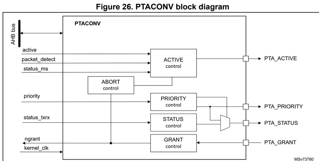
Figure 26. PTACONV block diagram
The diagram illustrates the internal architecture of the PTACONV block. On the left, an AHB bus is connected to the main PTACONV block. Below the bus, several input signals are shown: active , packet_detect , and status_ms entering the ACTIVE control block; priority entering the PRIORITY control block; status_btrx entering the STATUS control block; and ngrant and kernel_clk entering the GRANT control block. An ABORT control block is also present, receiving inputs from active , packet_detect , and status_ms . The ACTIVE control block outputs PTA_ACTIVE . The PRIORITY control block outputs PTA_PRIORITY . The STATUS control block outputs PTA_STATUS . The GRANT control block outputs PTA_GRANT . A multiplexer is shown selecting between the outputs of the PRIORITY control and the STATUS control to drive the PTA_STATUS output. The reference code MSv73760 is located in the bottom right corner of the diagram.
The PTACONV is clocked by the 2.4 GHz RADIO kernel clock independently of the hclk, which is used to access the PTACONV configuration registers.
10.3.2 PTACONV pins and internal signals
Table 81. 2.4 PTACONV input/output pins
| Pin name | Signal type | Description |
|---|---|---|
| PTA_ACTIVE | Output | PTA 2.4 GHz RADIO packet activation request |
| PTA_PRIORITY | Output | PTA 2.4 GHz RADIO packet priority |
| PTA_STATUS | Output | PTA 2.4 GHz RADIO packet type |
| PTA_GRANT | Input | PTA grant medium to 2.4 GHz RADIO |
Table 82. PTACONV internal input/output signals
| Pin name | Signal type | Description |
|---|---|---|
| active | Input | 2.4 GHz RADIO packet activation request |
| priority | Input | 2.4 GHz RADIO packet priority |
| status_txrx | Input | 2.4 GHz RADIO packet type Tx or Rx |
| status_ms | Input | 2.4 GHz RADIO packet type maser or slave |
| packet_detect | Input | 2.4 GHz RADIO packet detect |
| ngrant | Output | PTA active low medium granted |
| kernel_clk | Input | Kernel clock |
| hclk | Input/output | AHB bus interface |
10.4 PTACONV in low-power modes
The PTACONV supports operation in various low-power modes, as summarized in the table below:
Table 83. Effect of low-power modes on the PTACONV
| Mode | Description |
|---|---|
| Sleep | No effect. PTACONV remains operational. |
| Stop 0 (voltage scaling range 1) | No effect. PTACONV remains operational. |
| Stop 0 (voltage range 2) and Stop 1 | The PTACONV register context is retained, and PTA signals maintain their values. |
| Stop 2 | The PTACONV is powered down. PTA signals retain their values when enabled via PWR_S2RETR register. |
| Standby retention, Standby | The PTACONV is powered down. PTA signals retain their values when enabled via PWR_IORETENRx register. |
10.5 PTACONV protocols
The PTA grant protocol, the PTA deny protocol, and the 3-wire PTA_STATUS time-multiplexed priority and status transmit/receive information are detailed in this section.
PTA grant protocol
The 4-wire PTA grant protocol uses PTA_ACTIVE, PTA_STATUS, PTA_PRIORITY, and PTA_GRANT signals, as shown in Figure 27.
Figure 27. 4-wire PTA grant protocol
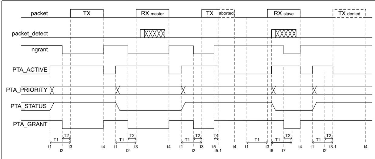
The timing diagram illustrates the 4-wire PTA grant protocol across several signal lines: packet, packet_detect, ngrant, PTA_ACTIVE, PTA_PRIORITY, and PTA_GRANT. The diagram is divided into four main phases: TX, RX master, TX aborted, and RX slave, followed by a TX denied state. The packet line shows a high level during TX and RX master phases, dropping to low during RX slave and TX denied. packet_detect is high during RX master and RX slave. ngrant is high during TX and RX master, dropping to low during RX slave. PTA_ACTIVE is high during TX and RX master, dropping to low during RX slave. PTA_PRIORITY and PTA_GRANT are shown as multiplexed signals with 'X' marks indicating active periods. Timing parameters T1, T2, and T4 are indicated at the bottom, showing the time required for PTA_ACTIVE to request the medium, the time before the start of the 2.4 GHz RADIO packet transfer, and the delay time required to stop an ongoing transmission, respectively.
Timing parameters:
- • T1 is the time required for the PTA_ACTIVE signal to request the medium before the start of the 2.4 GHz RADIO packet transfer.
- • T2 is the time before the start of the 2.4 GHz RADIO packet transfer, during which the PTA_GRANT is stable.
- • T4 is the delay time required to stop an ongoing 2.4 GHz RADIO packet transmission and deactivate PTA_ACTIVE. If a request to stop the transmission occurs near the end of the packet, PTA_ACTIVE will be deactivated at the end of the packet before T4 expires.
Time instances:
- • t1 is the instance that the request signal is activated before the 2.4 GHz RADIO packet transfer. For transmit and receive controller packets, t1 is also the time PTA_ACTIVE is activated.
- • t2 is the instance at which the PTA_GRANT signal is stable.
- • t3 is the start of the 2.4 GHz RADIO packet transfer.
- • t3.1 is the instance at which the 2.4 GHz RADIO packet transfer is denied, and PTA_ACTIVE is deactivated. The external PTA controller can also remove the PTA_GRANT.
- • t4 indicates the end of the 2.4 GHz RADIO packet and the deactivation of the active signal and PTA_ACTIVE signal if it is active. The external PTA controller can also remove the PTA_GRANT.
- • t5 is the time at which PTA_GRANT goes to deny and request to cease the ongoing packet transmission.
- • t5.1 indicates that the ongoing packet is aborted and the PTA_ACTIVE signal will be deactivated. Abortion of the transmit packet can be disabled with register bit ABORTDIS. In this case, the ngrant signal stays low until the end of the transmit packet.
- • t6 is the instance that the receive packet has been detected and used for subordinate receive packets to activate the PTA_ACTIVE signal.
- • t7 is the instance that the PTA_GRANT is stable.
Receive packets are always granted and reception always proceeds. Receive packets use the PTA protocol to request the reservation of the medium for high priority receive packets.
PTA deny protocol
The PTA deny protocol uses PTA_ACTIVE, PTA_STATUS, PTA_PRIORITY and PTA_DENY signals, as shown in Figure 28 .
Figure 28. 4-wire PTA deny protocol
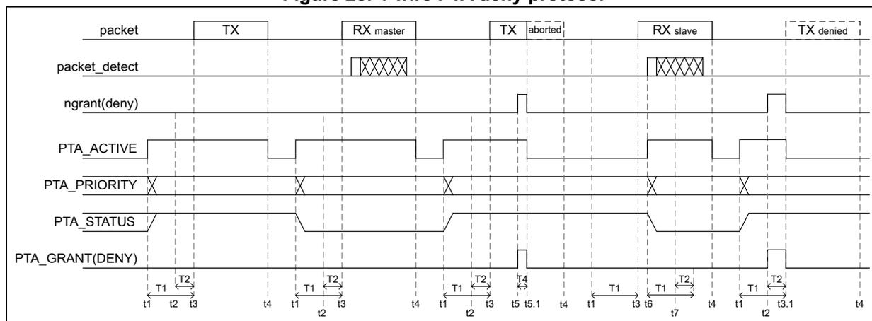
The timing diagram illustrates the 4-wire PTA deny protocol across several packet scenarios: TX, RX master, TX aborted, RX slave, and TX denied. The signals shown are packet_detect, ngrant(deny), PTA_ACTIVE, PTA_PRIORITY, PTA_STATUS, and PTA_GRANT(DENY). Time instances t1 through t7 are indicated at the bottom of the diagram to show the sequence of signal changes relative to packet transmission. For example, in the 'TX' packet case, PTA_ACTIVE goes high at t1, PTA_GRANT(DENY) goes high at t2, and the packet transfer starts at t3. In the 'TX aborted' case, PTA_GRANT(DENY) goes low at t5, and PTA_ACTIVE goes low at t5.1.
Timing parameters:
- • T1 is the time for the PTA_ACTIVE signal to request the medium before the start of the 2.4 GHz RADIO packet transfer.
- • T2 is the time before the start of the 2.4 GHz RADIO packet transfer, during which the PTA_GRANT is stable.
Time instances:
- • t1 is the instance that the request signal is activated before the 2.4 GHz RADIO packet transfer. For transmit and receive controller packets t1 is also the time PTA_ACTIVE is activated.
- • t2 is the instance at which the PTA_GRANT signal is stable.
- • t3 is the start of the 2.4 GHz RADIO packet transfer.
- • t3.1 is the instance at which a 2.4 GHz RADIO packet transfer is denied, and PTA_ACTIVE is deactivated. The external PTA controller can also remove the PTA_GRANT.
- • t4 indicates the end of the 2.4 GHz RADIO packet and the deactivation of the active signal and PTA_ACTIVE signal if they are active. The external PTA controller can also remove the PTA_GRANT.
- • t5 is the time at which PTA_GRANT goes to deny and request to cease the ongoing packet transmission.
- • t5.1 indicates that the ongoing packet is aborted and the PTA_ACTIVE signal will be deactivated. Abortion of the transmit packet can be disabled with register bit ABORTDIS. In this case, the deny signal stays high until the end of the transmit packet.
- • t6 is the instance the receive packet has been detected and used for subordinate receive packets to activate the PTA_ACTIVE signal.
- • t7 is the instance the PTA_GRANT is stable.
Receive packets are always granted and reception always proceeds. Receive packets use the PTA protocol to request the reservation of the medium for high priority receive packets.
3-wire time shared PTA_STATUS
The 3-wire PTA protocol does not use the PTA_PRIORITY signal. The priority and transmit receive packet status information is time-multiplexed on the PTA_STATUS signal, as shown in Figure 29.
Figure 29. 3-wire time-multiplexed PTA_STATUS
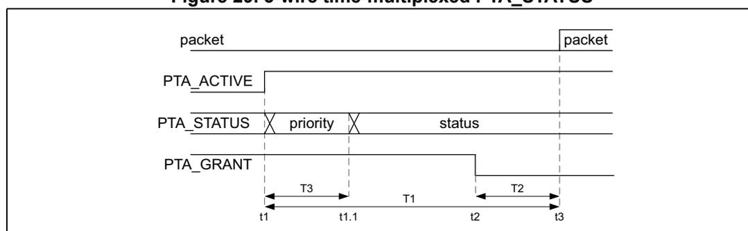
Timing parameters:
- • T1 is the time for the PTA_ACTIVE to request the medium before the start of the 2.4 GHz RADIO packet transfer.
- • T2 is the time before the start of the 2.4 GHz RADIO packet transfer during which the PTA_GRANT is stable.
- • T3 is the time that the priority is time-multiplexed on the PTA_STATUS signal.
Time instances:
- • t1 is the instance that the request signal is activated before the 2.4 GHz RADIO packet transfer. For transmit and receive controller packets it is also the time PTA_ACTIVE is activated. Priority information is time-multiplexed on the PTA_STATUS signal.
- • t1.1 is the instance at which the transmit or receive status is time-multiplexed on the PTA_STATUS signal.
- • t2 is the instance at which the PTA_GRANT signal is stable.
- • t3 is the start of the 2.4 GHz RADIO packet transfer.
PTA timing parameters
Table 84. 2.4 PTACONV timing parameters
| Symbol | Parameter | Min | Typ | Max | Unit |
|---|---|---|---|---|---|
| T1, T 1_PTA | PTA_ACTIVE setup time | 20 | - | 150 | µs |
| T 1_PTA_jitter | PTA_ACTIVE setup time jitter | -2 | - | 2 | |
| T2, T 2_PTA | PTA_GRANT setup time | 5 | - | - | |
| T3, T 3_PTA | PTA_STATUS priority valid time | 8 | - | 20 | |
| T4, T 4_PTA | Transmit packet abort delay | 5 | - | 10 |
10.5.1 PTACONV interface with the 2.4 GHz RADIO
The 2.4 GHz RADIO provides the following signals:
- • active:
- – activated with a T1 setup time before the start of the packet. This is before:
- > The PA ramping for transmit packet
- > The start of the receive window for receive packets
- – deactivated at the end of the scheduled packet. This is after:
- > The PA has ramped down for transmit packets
- > The last receive packet bit has been received, or at the end of the review window when no packet is detected
- – activated with a T1 setup time before the start of the packet. This is before:
- • priority: signaling 0 for low-priority packets, 1 for high priority packets
- • status_txrx: signaling 0 for receive packets, 1 for transmit packets
- • status_ms: signaling 0 for controller packets, 1 for subordinate packets
- • packet_detect: receive packet (access code) detect indication
- • ngrant: active low grant signal
- – To be sampled during the valid window T2 to determine whether a packet transmission is granted or denied
- – Monitored during the transmit packet to cease transmission upon the reception of a deny
10.6 PTACONV registers
10.6.1 PTACONV active control register (PTACONV_ACTCR)
Address offset: 0x000
Reset value: 0x0005 0014
Access: no wait state; word, half-word, and byte access
| 31 | 30 | 29 | 28 | 27 | 26 | 25 | 24 | 23 | 22 | 21 | 20 | 19 | 18 | 17 | 16 |
|---|---|---|---|---|---|---|---|---|---|---|---|---|---|---|---|
| Res. | Res. | Res. | Res. | Res. | Res. | Res. | Res. | Res. | Res. | Res. | ABORT DIS | TABORT[3:0] | |||
| rw | rw | rw | rw | rw | |||||||||||
| 15 | 14 | 13 | 12 | 11 | 10 | 9 | 8 | 7 | 6 | 5 | 4 | 3 | 2 | 1 | 0 |
| ACTPOL | Res. | Res. | Res. | Res. | Res. | Res. | Res. | TACTIVE[7:0] | |||||||
| rw | rw | rw | rw | rw | rw | rw | rw | rw | |||||||
Bits 31:21 Reserved, must be kept at reset value.
Bit 20 ABORTDIS : Disable PTA_ACTIVE deny to abort an ongoing transmission
- Set and cleared by software to define if PTA_ACTIVE will abort an ongoing transmission.
- 0: PTA_ACTIVE deny will abort an ongoing transmission
- 1: PTA_ACTIVE deny will not abort an ongoing transmission
Bits 19:16 TABORT[3:0] : PTA_ACTIVE delay to cease an ongoing transmission in \( \mu\text{s} \)
- Set and cleared by software to define transmit packet abort delay and signaling on PTA_ACTIVE.
- 0x5 to 0xA: transmit packet PTA_ACTIVE abort delay time: \( T_{4\_PTA} = \text{TABORT} \times 1 \mu\text{s} \)
- Others: reserved
Bit 15 ACTPOL : PTA_ACTIVE polarity
- Set and cleared by software to define PTA_ACTIVE signal polarity.
- 0: PTA_ACTIVE active high
- 1: PTA_ACTIVE active low
Bits 14:8 Reserved, must be kept at reset value.
Bits 7:0 TACTIVE[7:0] : PTA_ACTIVE setup time in \( \mu\text{s} \)
- Set and cleared by software to define PTA_ACTIVE setup time.
- 0x14 to 0x96: PTA_ACTIVE setup time: \( T_{1\_PTA} = \text{TACTIVE} \times 1 \mu\text{s} \)
- Others: reserved
10.6.2 PTACONV priority control register (PTACONV_PRICR)
Address offset: 0x004
Reset value: 0x0000 000A
Access: no wait state; word, half-word, and byte access
| 31 | 30 | 29 | 28 | 27 | 26 | 25 | 24 | 23 | 22 | 21 | 20 | 19 | 18 | 17 | 16 |
|---|---|---|---|---|---|---|---|---|---|---|---|---|---|---|---|
| Res. | Res. | Res. | Res. | Res. | Res. | Res. | Res. | Res. | Res. | Res. | Res. | Res. | Res. | Res. | Res. |
| 15 | 14 | 13 | 12 | 11 | 10 | 9 | 8 | 7 | 6 | 5 | 4 | 3 | 2 | 1 | 0 |
| PRIPOL | Res. | Res. | Res. | Res. | Res. | Res. | Res. | Res. | Res. | Res. | TPRIORITY[4:0] | ||||
| rw | rw | rw | rw | rw | rw | ||||||||||
Bits 31:16 Reserved, must be kept at reset value.
Bit 15 PRIPOL : Priority polarity
Set and cleared by software to define PTA_PRIOROITY and time-multiplexed priority on PTA_STATUS signal polarity.
0: priority on PTA_PRIORITY or PTA_STATUS not inverted
1: inverted priority on PTA_PRIORITY or PTA_STATUS
Bits 14:5 Reserved, must be kept at reset value.
Bits 4:0 TPRIORITY[4:0] : Priority valid time in \( \mu s \)
Set and cleared by software to define PTA_STATUS signal priority valid time.
0x00: no time-multiplexed priority information on PTA_STATUS
0x08 to 0x14: priority information multiplexed on PTA_STATUS with valid time:
\(
T_{3\_PTA} = TPRIORITY \times 1 \mu s
\)
Others: reserved
10.6.3 PTACONV control register (PTACONV_CR)
Address offset: 0x008
Reset value: 0x0000 0000
Access: no wait state; word, half-word, and byte access
| 31 | 30 | 29 | 28 | 27 | 26 | 25 | 24 | 23 | 22 | 21 | 20 | 19 | 18 | 17 | 16 |
|---|---|---|---|---|---|---|---|---|---|---|---|---|---|---|---|
| GRANT POL | Res. | Res. | Res. | Res. | Res. | Res. | Res. | Res. | Res. | Res. | Res. | Res. | Res. | Res. | Res. |
| rw | |||||||||||||||
| 15 | 14 | 13 | 12 | 11 | 10 | 9 | 8 | 7 | 6 | 5 | 4 | 3 | 2 | 1 | 0 |
| TXRX POL | Res. | Res. | Res. | Res. | Res. | Res. | Res. | Res. | Res. | Res. | Res. | Res. | Res. | Res. | Res. |
| rw |
Bit 31 GRANTPOL : PTA_GRANT polarity
Set and cleared by software to define PTA_GRANT signal polarity.
0: PTA_GRANT active low
1: PTA_GRANT active high
Bits 30:16 Reserved, must be kept at reset value.
Bit 15 TXRXPOL : PTA_STATUS transmit and receive polarity
Set and cleared by software to define PTA_STATUS signal polarity for transmit and receive information.
0: PTA_STATUS receive = 0, transmit = 1
1: PTA_STATUS receive = 1, transmit = 0
Bits 14:0 Reserved, must be kept at reset value.
10.6.4 PTACONV register map
Table 85. PTACONV register map and reset values
| Offset | Register | 31 | 30 | 29 | 28 | 27 | 26 | 25 | 24 | 23 | 22 | 21 | 20 | 19 | 18 | 17 | 16 | 15 | 14 | 13 | 12 | 11 | 10 | 9 | 8 | 7 | 6 | 5 | 4 | 3 | 2 | 1 | 0 |
|---|---|---|---|---|---|---|---|---|---|---|---|---|---|---|---|---|---|---|---|---|---|---|---|---|---|---|---|---|---|---|---|---|---|
| 0x000 | PTACONV_ACTCR | Res | Res | Res | Res | Res | Res | Res | Res | Res | Res | Res | ABORTDIS | TABORT[3:0] | ACTPOL | Res | Res | Res | Res | Res | Res | Res | Res | TACTIVE[7:0] | |||||||||
| Reset value | 0 | 0 | 1 | 0 | 1 | 0 | 0 | 0 | 0 | 1 | 0 | 1 | 0 | 0 | |||||||||||||||||||
| 0x004 | PTACONV_PRIOR | Res | Res | Res | Res | Res | Res | Res | Res | Res | Res | Res | Res | Res | Res | Res | Res | PRIPOL | Res | Res | Res | Res | Res | Res | Res | Res | Res | Res | TPRIORITY[4:0] | ||||
| Reset value | 0 | 0 | 1 | 0 | 1 | 0 | |||||||||||||||||||||||||||
| 0x008 | PTACONV_CR | GRANTPOL | Res | Res | Res | Res | Res | Res | Res | Res | Res | Res | Res | Res | Res | Res | Res | TXRPOL | Res | Res | Res | Res | Res | Res | Res | Res | Res | Res | Res | Res | Res | Res | Res |
| Reset value | 0 | 0 | |||||||||||||||||||||||||||||||
| 0x00C to 0x3FC | Reserved | Reserved | |||||||||||||||||||||||||||||||
Refer to Section 2.3: Memory organization for the register boundary addresses.