15. Cyclic redundancy check calculation unit (CRC)
15.1 Introduction
The CRC (cyclic redundancy check) calculation unit is used to get a CRC code from 8-, 16- or 32-bit data word and a generator polynomial.
Among other applications, CRC-based techniques are used to verify data transmission or storage integrity. In the scope of the functional safety standards, they offer a means of verifying the flash memory integrity. The CRC calculation unit helps compute a signature of the software during runtime, to be compared with a reference signature generated at link time and stored at a given memory location.
15.2 CRC main features
- • Uses CRC-32 (Ethernet) polynomial:\[ X^{32} + X^{26} + X^{23} + X^{22} + X^{16} + X^{12} + X^{11} + X^{10} + X^8 + X^7 + X^5 + X^4 + X^2 + X + 1 \]
- • Alternatively, uses fully programmable polynomial with programmable size (7, 8, 16, 32 bits)
- • Handles 8-, 16-, 32-bit data size
- • Programmable CRC initial value
- • Single input/output 32-bit data register
- • Input buffer to avoid bus stall during calculation
- • CRC computation done in 4 AHB clock cycles (HCLK) for the 32-bit data size
- • General-purpose 8-bit register (can be used for temporary storage)
- • Reversibility option on I/O data
- • Accessed through AHB slave peripheral by 32-bit words only, with the exception of CRC_DR register that can be accessed by words, right-aligned half-words and right-aligned bytes
15.3 CRC functional description
15.3.1 CRC block diagram
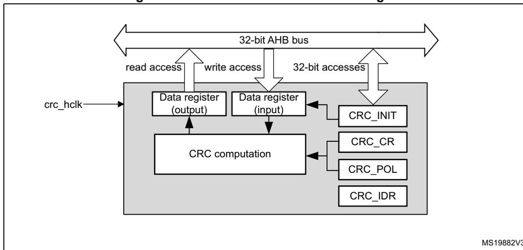
Figure 29. CRC calculation unit block diagram
15.3.2 CRC internal signals
Table 63. CRC internal input/output signals
| Signal name | Signal type | Description |
|---|---|---|
| crc_hclk | Digital input | AHB clock |
15.3.3 CRC operation
The CRC calculation unit has a single 32-bit read/write data register (CRC_DR). It is used to input new data (write access), and holds the result of the previous CRC calculation (read access).
Each write operation to the data register creates a combination of the previous CRC value (stored in CRC_DR) and the new one. CRC computation is done on the whole 32-bit data word or byte by byte depending on the format of the data being written.
The CRC_DR register can be accessed by word, right-aligned half-word and right-aligned byte. For the other registers only 32-bit accesses are allowed.
The duration of the computation depends on data width:
- • 4 AHB clock cycles for 32 bits
- • 2 AHB clock cycles for 16 bits
- • 1 AHB clock cycles for 8 bits
An input buffer allows a second data to be immediately written without waiting for any wait-states due to the previous CRC calculation.
The data size can be dynamically adjusted to minimize the number of write accesses for a given number of bytes. For instance, a CRC for 5 bytes can be computed with a word write followed by a byte write.
The input data can be reversed to manage the various endianness schemes. The reversing operation can be performed on 8 bits, 16 bits and 32 bits depending on the REV_IN[1:0] bits in the CRC_CR register.
For example, 0x1A2B3C4D input data are used for CRC calculation as:
- • 0x58D43CB2 with bit-reversal done by byte
- • 0xD458B23C with bit-reversal done by half-word
- • 0xB23CD458 with bit-reversal done on the full word
The output data can also be reversed by setting the REV_OUT bit in the CRC_CR register.
The operation is done at bit level. For example, 0x11223344 output data are converted to 0x22CC4488.
The CRC calculator can be initialized to a programmable value using the RESET control bit in the CRC_CR register (the default value is 0xFFFFFFFF).
The initial CRC value can be programmed with the CRC_INIT register. The CRC_DR register is automatically initialized upon CRC_INIT register write access.
The CRC_IDR register can be used to hold a temporary value related to CRC calculation. It is not affected by the RESET bit in the CRC_CR register.
Polynomial programmability
The polynomial coefficients are fully programmable through the CRC_POL register, and the polynomial size can be configured to be 7, 8, 16 or 32 bits by programming the POLYSIZE[1:0] bits in the CRC_CR register. Even polynomials are not supported.
Note: The type of an even polynomial is \( X+X^2+\dots+X^n \) , while the type of an odd polynomial is \( 1+X+X^2+\dots+X^n \) .
If the CRC data is less than 32-bit, its value can be read from the least significant bits of the CRC_DR register.
To obtain a reliable CRC calculation, the change on-fly of the polynomial value or size can not be performed during a CRC calculation. As a result, if a CRC calculation is ongoing, the application must either reset it or perform a CRC_DR read before changing the polynomial.
The default polynomial value is the CRC-32 (Ethernet) polynomial: 0x4C11DB7.
15.4 CRC registers
The CRC_DR register can be accessed by words, right-aligned half-words and right-aligned bytes. For the other registers only 32-bit accesses are allowed.
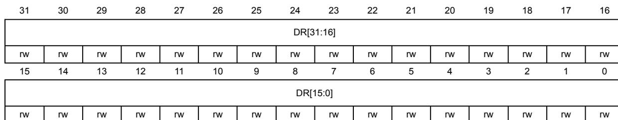
15.4.1 CRC data register (CRC_DR)
Address offset: 0x00
Reset value: 0xFFFF FFFF
| 31 | 30 | 29 | 28 | 27 | 26 | 25 | 24 | 23 | 22 | 21 | 20 | 19 | 18 | 17 | 16 |
| DR[31:16] | |||||||||||||||
| rw | rw | rw | rw | rw | rw | rw | rw | rw | rw | rw | rw | rw | rw | rw | rw |
| 15 | 14 | 13 | 12 | 11 | 10 | 9 | 8 | 7 | 6 | 5 | 4 | 3 | 2 | 1 | 0 |
| DR[15:0] | |||||||||||||||
| rw | rw | rw | rw | rw | rw | rw | rw | rw | rw | rw | rw | rw | rw | rw | rw |
Bits 31:0 DR[31:0] : Data register bits
This register is used to write new data to the CRC calculator.
It holds the previous CRC calculation result when it is read.
If the data size is less than 32 bits, the least significant bits are used to write/read the correct value.
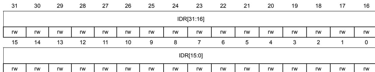
15.4.2 CRC independent data register (CRC_IDR)
Address offset: 0x04
Reset value: 0x0000 0000
| 31 | 30 | 29 | 28 | 27 | 26 | 25 | 24 | 23 | 22 | 21 | 20 | 19 | 18 | 17 | 16 |
| IDR[31:16] | |||||||||||||||
| rw | rw | rw | rw | rw | rw | rw | rw | rw | rw | rw | rw | rw | rw | rw | rw |
| 15 | 14 | 13 | 12 | 11 | 10 | 9 | 8 | 7 | 6 | 5 | 4 | 3 | 2 | 1 | 0 |
| IDR[15:0] | |||||||||||||||
| rw | rw | rw | rw | rw | rw | rw | rw | rw | rw | rw | rw | rw | rw | rw | rw |
Bits 31:0 IDR[31:0] : General-purpose 32-bit data register bits
These bits can be used as a temporary storage location for four bytes.
This register is not affected by CRC resets generated by the RESET bit in the CRC_CR register
15.4.3 CRC control register (CRC_CR)
Address offset: 0x08
Reset value: 0x0000 0000
| 31 | 30 | 29 | 28 | 27 | 26 | 25 | 24 | 23 | 22 | 21 | 20 | 19 | 18 | 17 | 16 |
|---|---|---|---|---|---|---|---|---|---|---|---|---|---|---|---|
| Res. | Res. | Res. | Res. | Res. | Res. | Res. | Res. | Res. | Res. | Res. | Res. | Res. | Res. | Res. | Res. |
| 15 | 14 | 13 | 12 | 11 | 10 | 9 | 8 | 7 | 6 | 5 | 4 | 3 | 2 | 1 | 0 |
| Res. | Res. | Res. | Res. | Res. | Res. | Res. | Res. | REV_OUT | REV_IN[1:0] | POLYSIZE[1:0] | Res. | Res. | RESET | ||
| rw | rw | rw | rw | rw | rs | ||||||||||
Bits 31:8 Reserved, must be kept at reset value.
Bit 7 REV_OUT : Reverse output data
This bit controls the reversal of the bit order of the output data.
0: Bit order not affected
1: Bit-reversed output format
Bits 6:5 REV_IN[1:0] : Reverse input data
This bitfield controls the reversal of the bit order of the input data
00: Bit order not affected
01: Bit reversal done by byte
10: Bit reversal done by half-word
11: Bit reversal done by word
Bits 4:3 POLYSIZE[1:0] : Polynomial size
These bits control the size of the polynomial.
00: 32 bit polynomial
01: 16 bit polynomial
10: 8 bit polynomial
11: 7 bit polynomial
Bits 2:1 Reserved, must be kept at reset value.
Bit 0 RESET : RESET bit
This bit is set by software to reset the CRC calculation unit and set the data register to the value stored in the CRC_INIT register. This bit can only be set, it is automatically cleared by hardware
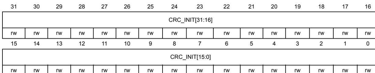
15.4.4 CRC initial value (CRC_INIT)
Address offset: 0x10
Reset value: 0xFFFF FFFF
| 31 | 30 | 29 | 28 | 27 | 26 | 25 | 24 | 23 | 22 | 21 | 20 | 19 | 18 | 17 | 16 |
| CRC_INIT[31:16] | |||||||||||||||
| rw | rw | rw | rw | rw | rw | rw | rw | rw | rw | rw | rw | rw | rw | rw | rw |
| 15 | 14 | 13 | 12 | 11 | 10 | 9 | 8 | 7 | 6 | 5 | 4 | 3 | 2 | 1 | 0 |
| CRC_INIT[15:0] | |||||||||||||||
| rw | rw | rw | rw | rw | rw | rw | rw | rw | rw | rw | rw | rw | rw | rw | rw |
Bits 31:0 CRC_INIT[31:0] : Programmable initial CRC value
This register is used to write the CRC initial value.
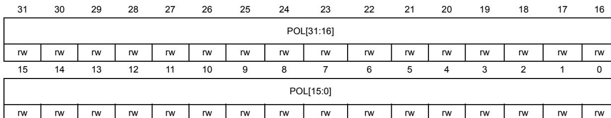
15.4.5 CRC polynomial (CRC_POL)
Address offset: 0x14
Reset value: 0x04C1 1DB7
| 31 | 30 | 29 | 28 | 27 | 26 | 25 | 24 | 23 | 22 | 21 | 20 | 19 | 18 | 17 | 16 |
| POL[31:16] | |||||||||||||||
| rw | rw | rw | rw | rw | rw | rw | rw | rw | rw | rw | rw | rw | rw | rw | rw |
| 15 | 14 | 13 | 12 | 11 | 10 | 9 | 8 | 7 | 6 | 5 | 4 | 3 | 2 | 1 | 0 |
| POL[15:0] | |||||||||||||||
| rw | rw | rw | rw | rw | rw | rw | rw | rw | rw | rw | rw | rw | rw | rw | rw |
Bits 31:0 POL[31:0] : Programmable polynomial
This register is used to write the coefficients of the polynomial to be used for CRC calculation.
If the polynomial size is less than 32 bits, the least significant bits have to be used to program the correct value.
15.4.6 CRC register map
Table 64. CRC register map and reset values
| Offset | Register name | 31 | 30 | 29 | 28 | 27 | 26 | 25 | 24 | 23 | 22 | 21 | 20 | 19 | 18 | 17 | 16 | 15 | 14 | 13 | 12 | 11 | 10 | 9 | 8 | 7 | 6 | 5 | 4 | 3 | 2 | 1 | 0 |
|---|---|---|---|---|---|---|---|---|---|---|---|---|---|---|---|---|---|---|---|---|---|---|---|---|---|---|---|---|---|---|---|---|---|
| 0x00 | CRC_DR | DR[31:0] | |||||||||||||||||||||||||||||||
| Reset value | 1 | 1 | 1 | 1 | 1 | 1 | 1 | 1 | 1 | 1 | 1 | 1 | 1 | 1 | 1 | 1 | 1 | 1 | 1 | 1 | 1 | 1 | 1 | 1 | 1 | 1 | 1 | 1 | 1 | 1 | 1 | 1 | |
| 0x04 | CRC_IDR | IDR[31:0] | |||||||||||||||||||||||||||||||
| Reset value | 0 | 0 | 0 | 0 | 0 | 0 | 0 | 0 | 0 | 0 | 0 | 0 | 0 | 0 | 0 | 0 | 0 | 0 | 0 | 0 | 0 | 0 | 0 | 0 | 0 | 0 | 0 | 0 | 0 | 0 | 0 | ||
| 0x08 | CRC_CR | Res | Res | Res | Res | Res | Res | Res | Res | Res | Res | Res | Res | Res | Res | Res | Res | Res | Res | Res | Res | Res | Res | Res | Res | REV_OUT | REV_IN[1:0] | POLYSIZE[1:0] | Res | Res | RESET | ||
| Reset value | 0 | 0 | 0 | ||||||||||||||||||||||||||||||
| 0x10 | CRC_INIT | CRC_INIT[31:0] | |||||||||||||||||||||||||||||||
| Reset value | 1 | 1 | 1 | 1 | 1 | 1 | 1 | 1 | 1 | 1 | 1 | 1 | 1 | 1 | 1 | 1 | 1 | 1 | 1 | 1 | 1 | 1 | 1 | 1 | 1 | 1 | 1 | 1 | 1 | 1 | 1 | ||
| 0x14 | CRC_POL | POL[31:0] | |||||||||||||||||||||||||||||||
| Reset value | 0 | 0 | 0 | 0 | 0 | 1 | 0 | 0 | 1 | 1 | 0 | 0 | 0 | 0 | 0 | 1 | 0 | 0 | 0 | 1 | 1 | 1 | 0 | 1 | 1 | 0 | 1 | 1 | 0 | 1 | 1 | ||
Refer to Section 2.2 for the register boundary addresses.