37. Camera subsystem
37.1 Introduction
The camera subsystem is built around a double path:
- • a low-resolution path, with the DCMI and a low-frequency parallel interface. It supports sensors up to 24 Mpixel/s.
- • a high-resolution path, with the DCMIPP and a high-frequency parallel interface or serial CSI-2 interface, either RGB or RawBayer. It targets sensors up to 5 Mpixels at 30 fps.
When plugging a camera sensor, it is recommended to use the DCMIPP, a higher performance pipe.
The previous DCMI is recommended only in two noticeable cases:
- • to get a backward compatibility with former platforms that embed also the DCMI
- • to input the pixels from a second camera sensor
Note: The DCMIPP inputs pixels from one sensor via the CSI-2 interface, while the DCMI gets pixels from the second sensor via the parallel interface.
The DCMI path offers the following summarized maximum features:
- • Target sensor: 24 Mpixel/s 16 bpp (limited by the DMA)
- • Parallel input: 80 MHz on 14-bit input capability
- • Central DMA to extract and dump its pixels
- • Software extraction of its pixel data
The DCMIPP path offers the following summarized maximum features:
- • Target sensors: 5 Mpixel at 30 fps max
- • Parallel input: 120 MHz on 16-bit input capability
- • Serial input: CSI-2 at 2.5 Gbps/lane on 2 data lanes
- • ISP (image signal processor): demosaicing, exposure, white-balance, contrast, bad-pixel
- • Application pipes: 2 pipes with crop, downsize, gamma, YUV conversion, YUV420
Some over-target use cases are possible, but with specific constraints:
- • sensors with resolution above 5 Mpixels
- • sensors with pixel rate above 150 Mpixel/s
- • double sensors in parallel
37.2 Camera path main features
37.2.1 DCMI path main features
The DCMI path shows the following features:
- • 8-, 10-, 12- or 14-bit parallel interface at 80 MHz (no I/O ReTime)
- • Embedded/external line and frame synchronization
- • Continuous or snapshot mode
- • Crop feature
- • Following data formats supported (dumped in memory, extracted by software):
- – 8-, 10-, 12-, 14-bit progressive video, either monochrome or RawBayer
- – YCbCr 4:2:2 progressive video
- – RGB 565 progressive video
- – Compressed data: JPEG (in fact, any default/byte data)
See Section 38: Digital camera interface (DCMI) for more details.
37.2.2 DCMIPP path main features
The DCMIPP path groups the DCMIPP pixel pipeline block, its included parallel interface, and the abutted CSI-2-Host and PHY.
The parallel interface shows the following features:
- • Input rate: 120 MHz up to 16-bit capability (with I/O ReTime)
- • Pixel format: RGB565, 888, YUV422, RawBayer/Mono 8/10/12/14
- • Synchronization: embedded versus external line and frame synchronization
See Section 39: Digital camera interface pixel pipeline (DCMIPP) for more details.
The CSI-2 serial interface shows the following features:
- • Standard: MIPI CSI2 v1.3
- • Input rate: 2 data lanes @ 2.5 Gbps/lane
- • Pixel rate: if RGB888: up to 200 Mpixel/s, if RawBayer 10: up to 333 Mpixel/s
- • Pixel format: any MIPI CSI2 v1.3: RGB565, 888, YUV422, RawBayer
- • Miscellaneous: interlaced video, interleaved packets, virtual channels
See Section 40: CSI-2 Host (CSI) for more details.
DCMIPP sizings and limitations
- • Camera target: 5 Mpixels (typ. 2560x2048 or 2688x1944) before decimation
- • Pipe resolution: 4094x4094 pixels max
- – Demosaicing: 2688 pixels wide max line-buffers (decimation available ahead)
- – Downsize: 2688 pixels wide max line-buffers
- – YUV420: 2688 pixels wide max line-buffers.
- • Pipe pixel rate: 333 Mpixel/s peak.
- • AXI FIFO: 5 Kbytes available, with a flexible allocation between all outputs.
- • AXI master: AXI-64 bits @ 400 MHz, with FIFO for latencies up to 2 µs, 16 outstanding.
The DCMIPP provides three different pipes to process data:
- • Pipe0: to dump data without any processing, branched before any ISP
It is aimed at dumping metadata or statistics as-is from the sensor, or at dumping the full picture as RawBayer data, for a potential long but optimal software processing. - • Pipe1: main full-featured pipe (such as ISP, then downsize, YUV-multi-planar)
It provides a picture ready for any application (such as display, video encode, or neural processing).
- • Pipe2: ancillary semi-featured pipe
Same ISP as pipe1, then downsize, but no YUV-multiplanar. It provides an RGB output for a display use, or neural processing if using RGB as input.
DCMIPP ISP capabilities common to pipe1 and 2, are the following:
- • flow selection: parallel-vs-CSI2, CSI virtual packets
- • capture mode: continuous versus snapshot mode
- • pixel extraction: RGB565, 888, YUV422, RawBayer/Mono 8/10/12/14.
- • statistic removal: to remove unused metadata (like statistics) from received pictures
- • bad-pixel removal: automatic detection and correction of bad pixels from sensor array
- • decimation: one pixel every 1/2/4/8, used to fit the max 2688 pixels
- • exposure control: to amplify the exposure from 0.0 to 255.99x
- • statistic extraction: average R,G,B,L values, dynamic bins
- • demosaicing: to convert RawBayer to RGB, supports NIR patterns (2x2, 4x4)
- • white-balance: to adapt to sensor white and global illumination
- • contrast: to enhance the contrast, via luminance
The DCMIPP application capabilities, replicated for pipe1 and 2, are listed below:
- • cropping: to select a region of interest or stabilize the picture
- • downsize: box-filtering, with any decimal ratio, up to 8x8 (64x64 with decimation)
- • gamma conversion: predistortion with gamma = 2.2 for display purposes
- • YUV color conversion: to convert to YUV to later store a video-friendly buffer (pipe1 only).
- • YUV422/420: chroma subsampling to YUV422 or YUV420
- • output streaming capability of three pixel pipes to a slave peripheral (VENC, NPU, or LP/HPDMA1), using a small multiline internal buffer located in the system memory
- • regions of interest (ROI): draw capability of a colored rectangle around each ROI
Output pixel format:
- • Pipe1 and 2: 888, 565, 422-1, Y8, ARGB and RGBA (coplanar only)
- • Pipe1: to add 422-2, 420-2, 420-3 (multi-planar possibility)
The full features are detailed in Section 38: Digital camera interface (DCMI) .
37.3 Camera subsystem implementation
37.3.1 Hardware settings
The camera subsystem is implemented with the following specific settings:
- • CSI2: two data lanes (+ one clock lane) up to 2.5 Gbps/lane.
- • DCMIPP FIFO: 5 Kbytes for AXI
- • DCMIPP with the following subfeatures:
- – line-buffers: 2688 pixels (impacts the demosaicing, downsize, YUV420 conversion)
- – one dump pipe + two pixel pipes (pipe1 with YUV420/multi-planar only)
37.4 Camera subsystem functional description
37.4.1 Camera subsystem block diagram
Figure 386 shows the blocks in the camera subsystem.
Figure 386. Camera subsystem block diagram
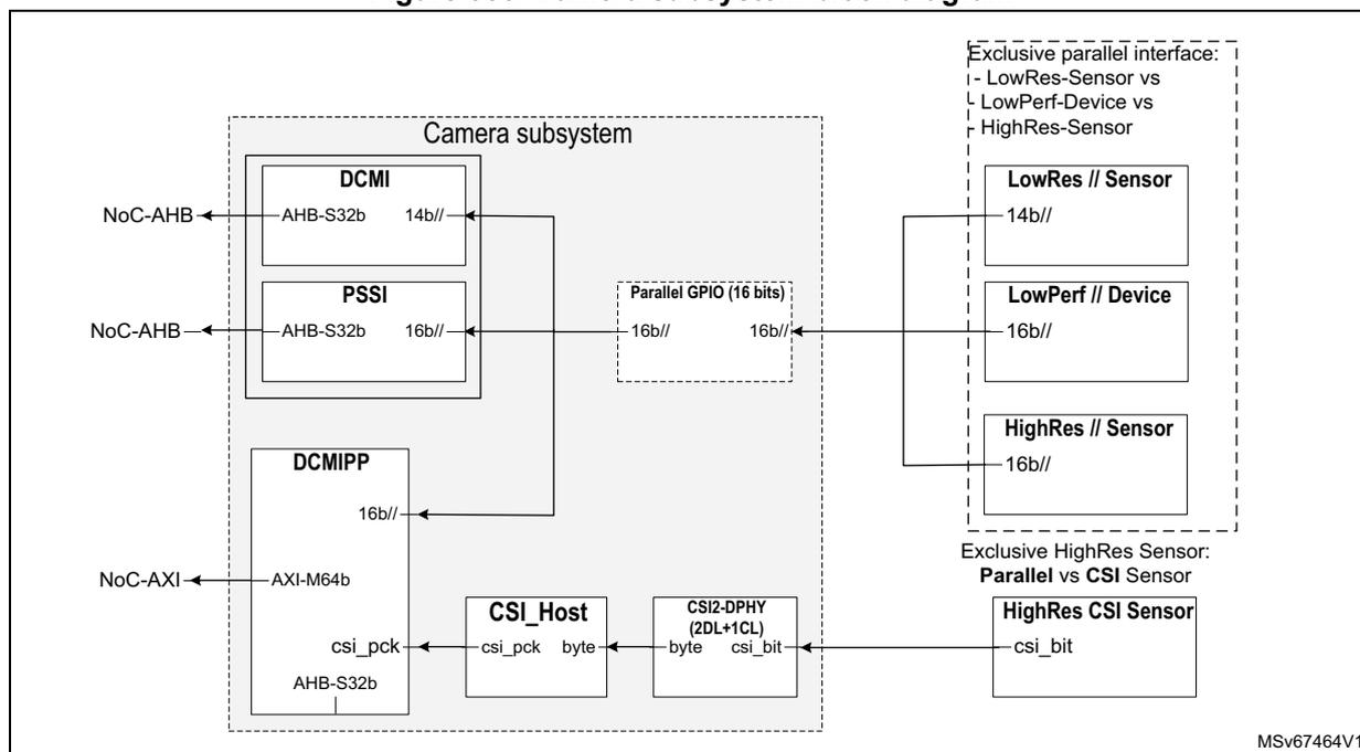
The block diagram illustrates the internal architecture of the camera subsystem and its interfaces to external sensors. The subsystem is enclosed in a dashed box labeled 'Camera subsystem' and contains the following components:
- DCMI : Connected to NoC-AHB via an AHB-S32b interface. It has a 14b// output.
- PSSI : Connected to NoC-AHB via an AHB-S32b interface. It has a 16b// output.
- DCMIPP : Connected to NoC-AXI via an AXI-M64b interface and to the CSI Host via an AHB-S32b interface. It has a 16b// output.
- CSI Host : Receives data from the DCMIPP via 'csi_pck' and 'byte' signals. It connects to the CSI2-DPHY.
- CSI2-DPHY (2DL+1CL) : Transfers 'byte' and 'csi_bit' data to the HighRes CSI Sensor.
- A 'Parallel GPIO (16 bits)' block receives 16b// signals from the PSSI and provides 16b// signals to the LowRes // Sensor (14b//), LowPerf // Device (16b//), and HighRes // Sensor (16b//). These three sensors are grouped under 'Exclusive parallel interface: - LowRes-Sensor vs LowPerf-Device vs HighRes-Sensor'.
- The HighRes CSI Sensor (csi_bit) is connected to the CSI2-DPHY. This sensor is under 'Exclusive HighRes Sensor: Parallel vs CSI Sensor'.
Note: The PSSI is not used for camera purposes, but rather for general-purpose parallel input (not described in this section).
37.4.2 Camera subsystem pins and external signal interface
Details about the pins can be found in the respective block sections.
37.4.3 Camera subsystem reset and clocks
The clock diagram of the camera subsystem is shown in Figure 387 .
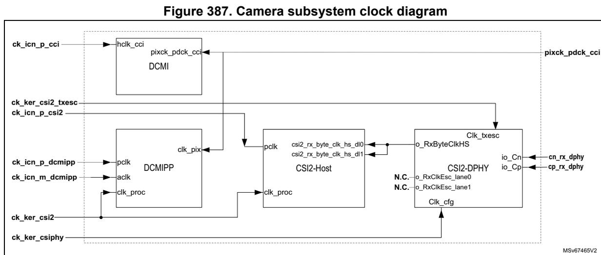
Figure 387. Camera subsystem clock diagram
The camera subsystem has been implemented with the following clock max frequencies:
- • DCMI // I/F (pixck_pdck_cci): 80 MHz (no I/O ReTime: async path from pads)
- • DCMIPP // I/F (pixck_pdck_cci): 120 MHz (I/O ReTime mandatory)
- • CSI2 bit clock (cn/p_rx_dphy): 1250 MHz (2.5 Gbps/lane)
- • CSI2 byte clock (rxbyte_clkHS): 312.5 MHz
- • CSI2 TxEsc clock (ck_ker_csi2_txesc): 20 MHz
- • CSI2 Cfg clock (ck_ker_csiphy): 20 MHz
- • Pixel clock (ck_ker_csi2): 333 MHz
- • Register clocks (ck_icn_p_*): 200 MHz (all APB/AHB register files)
- • AXI clock (ck_icn_m_dcmipp): 400 MHz
37.4.4 Streaming from the camera subsystem to slave peripherals
The DCMIPP in the camera subsystem can stream pixels to a set of slave peripherals NPU, HP/GPDMA, and VENC. This avoids to write the full frame into a frame buffer (and allocate this frame buffer).
The streaming is done via a small intermediate buffer in the system memory, organized in double ping-pong buffer. The double buffer must be a power-of-two amount of lines, with a recommended size of 16 lines high each.
The processing is as follows:
- 1. The DCMIPP starts writing into the first buffer.
- 2. After step 1 completion, the DCMIPP emits an hardware trigger signal to the slave peripheral, and continues to write to the second buffer.
- 3. At hardware trigger reception, the slave peripheral reads from the first buffer. It is expected to read and process the buffer faster than the DCMIPP fills the other.
- 4. After completing writing the second buffer, the DCMIPP emits again a trigger, and wraps back its write address counter to restart writing into the first buffer.
- 5. After finishing reading the second buffer, the slave peripheral wraps back reading into the first buffer.
All DCMIPP pipes can be streamed, but not to all slave peripherals:
- • Pipe0 (dump pipe) can be streamed to HP/GPDMA.
- • Pipe1 (main pixel pipe) can be streamed to HP/GPDMA, NPU, or VENC.
- • Pipe2 (aux pixel pipe) can be streamed to HP/GPDMA or NPU.
The VENC can only get streamed from Pipe1 (only pipe that can output a YUV420 pixel format, needed for its H264 or JPG encode).
A same pipe can be streamed simultaneously to several peripherals if the resolution and pixel format match: after receiving the same broadcasted trigger, the various slave peripherals simply read in parallel from the same shared intermediate buffer.
More information about the streaming can be found in the respective peripheral sections:
- • Section 39: Digital camera interface pixel pipeline (DCMIPP) (see pixel packing and streaming across a ping-pong buffer)
- • Section 20: Neural-ART accelerator™ (NPU)
- • Section 18: High-performance direct memory access controller (HPDMA)
- • Section 19: General purpose direct memory access controller (GPDMA)
- • Section 45: Video encoder (VENC)
37.4.5 Camera subsystem security
The security of the camera subsystem is based on the protection of its register map, and of its master access to the system interconnect, based on default RISUP and RIMU respectively.
More information can be found in Section 3.5.3: RIF infrastructure .
The RISUP differentiates the access right of accesses performed toward the following RIF protected peripheral ID (indexes refer to Table 20: RISUP indexes ):
- • DCMIPP: tag = DCMIPP for the configuration of pixel pipelines (index 93)
- • CSI2-Host: tag = CSI2H for Host and PHY configurations (index 926)
- • DCMI and PSSI: tag = DCMI for its configuration, and to retrieve pixels by DMA (index 94 and 95 respectively)
The RIMU (RIMU_AXI_DCMIPP) gives the access right to the DCMIPP AXI master: CID, S and P are set using the RIF RIMC_ATTR9 register (no inheritance from RISPU to RIMU).
- • CID is set either by the RISA (RISUP86 register) or directly by software.
By default, the camera subsystem is expected to work in a nonsecure mode:
- • DCMIPP, CSI2, DCMI, and PSSI are left unprotected, so that any OS software can configure and handle the camera subsystem.
- • The AXI master can be configured with a DCMIPP CID = DISP or CID = VID to mention that the AXI write access of the camera subsystem contains pixels (like the display system).
For secure applications, the user can put the camera subsystem in S, P, or S-and-P mode, with the following impacts:
- As a benefit, the user is sure that the content of the dumped buffer does truly come from the camera sensor:
The output of the DCMIPP is differentiated from other masters: only the DCMIPP can write into its buffer. This buffer content is known to come from the camera sensor, which makes impossible to fill-in (by software) a fake face to be recognized.
- The camera subsystem needs to be transferred to the secure software world (with the verification implications), or the system must make sure that the access rights of the DCMIPP cannot harm the system.
The above recommended non-protected settings are shown in Table 315: Camera subsystem RIF peripheral ID .
The table below lists vertically all camera subsystem blocks, and horizontally the associated RIF peripheral ID.
Table color legend for the recommended settings : gray for a permanently non-protected setting, blue for a temporarily protected versus non-protected, and pink for a permanently protected state: by default, all the settings are non-protected.
Table 315. Camera subsystem RIF peripheral ID
| Subsystem | Block | Address range | Start address | RISUP - slave | ||
|---|---|---|---|---|---|---|
| 94 and 95 | 93 | 92 | ||||
| DCMI and PSSI | DCMIPP | CSI2H | ||||
| Camera low resolution | DCMI | Configuration | 0x0000 | Y | - | - |
| Pixel Rx | 0x0A00 | Y | - | - | ||
| Configuration | 0x0B00 | Y | - | - | ||
| Data in/out | 0x0C00 | Y | - | - | ||
| Camera high resolution | DCMIPP | Common configuration | 0x0 | - | Y | - |
| P1 configuration | 0x0 | - | Y | - | ||
| P2 configuration | 0x0 | - | Y | - | ||
| P3 configuration | 0x0 | - | Y | - | ||
| CSI | Configuration control | 0x0000 | - | - | Y | |
| Configuration wrap | 0x1000 | - | - | Y | ||
| CSI DPHY-Rx (no register) | - | - | - | - | ||
37.5 Camera subsystem programmable parameters
This section describes the configuration of the various main use cases supported by the camera subsystem. Its purpose is to provide the settings that are global to the camera subsystem, and not provided by the local relevant blocks.
The use cases supported by default are the following:
- low-resolution parallel camera, using the DCMI path (see Section 37.5.1 )
- • high-resolution parallel camera, using the DCMIPP path (see Section 37.5.2 )
- • high-resolution CSI2 camera, using the DCMIPP path (see Section 37.5.3 )
Some over-target use cases are possible, but with specific constraints:
- • sensors over target-resolution (above 5 Mpixels)
The limiting factors are
- – the clock (related to max pixel rate)
- – AXI bandwidth (related to the pixel rate and pixel format of the active pipes)
- – line buffers of the demosaicing, downsize, and YUV420 chroma decimation (when active)
To cope with these limitations, the decimation can be used, ahead of the pipes, to reduce the width and/or height of the frame, and/or deactivate the limiting operators, the demosaicing, downsize, YUV420.
- • sensors over target pixel rate (above 150 Mpixel/s)
- • double sensors like 3D camera (with their left and right sensors)
37.5.1 Low-resolution parallel camera and DCMI
This use case is recommended only for backward compatibility, or to grab pictures simultaneously from two sensors (a low and a high resolution).
The steps to setup this path are the following:
- • Clock and reset
- – pixck_pdck_cci is provided by the sensor (via the PCB on the input I/O, 80 MHz max).
- – The RCC provides ck_icn_p_cci, that must be \( \geq 2.5 \times \) pixck_pdck_cci due to the DCMI. The default clock is 200 MHz, which allows the input clock to be at 80 MHz.
- – Section 20: Reset and clock control (RCC) provides the needed details.
- • DMA
- – The GPDMA and HPDMA retrieve pixels from the DCMI, that signals to the DMA that its FIFO is full and must be read-out.
- – Section 18 and Section 19 provide the needed details.
37.5.2 High-resolution parallel camera and DCMIPP
This is the default use case to grab a picture from a parallel camera (up to the target 5 Mpixels @30fps). Any RGB or RawBayer picture can be grabbed.
The steps to setup this path are the following:
- • Clock and reset:
- – pixck_pdck_cci is provided by the sensor (via the PCB on the input I/O, 120 MHz max). Each pixel needs 1 to 3 cycles to get in.
- – ck_icn_p_dcmipp is provided by the RCC for the DCMIPP configuration (default 200 MHz).
- – ck_ker_csi2 is provided by the RCC for the pixel pipelines of the DCMIPP (default 200 MHz).
- – ck_icn_m_dcmipp is provided by the RCC for the DCMIPP AXI (default 400 MHz).
- – Section 20: Reset and clock control (RCC) provides the needed details.
- • DCMIPP configuration:
- – Select the parallel interface as input interface.
- – Setup the DCMIPP (parallel interface, ISP, application path, AXI-plug) as described in Section 39: Digital camera interface pixel pipeline (DCMIPP) .
37.5.3 High-resolution CSI2 camera and DCMIPP
This is the default use-case to grab a picture from a CSI2 camera (up to the target 5 Mpixels @30 fps). Any RGB or RawBayer picture can be grabbed.
The steps to setup this path are the following:
- • Clock and reset:
- – cn/p_rx_dphy are provided by the sensor (via the PCB on the input I/O, 1.25 GHz/2.5 Gbit/s max).
- – RxByteClkHS is automatically divided (1/8) from cn/p_rx_dphy (312.5 MHz max).
- – ck_icn_p_csi2 is provided by the RCC for the CSI2-Host configuration (default 200 MHz).
- – ck_icn_p_dcmipp is provided by the RCC for the DCMIPP configuration (default 200 MHz).
- – ck_ker_csiphy is provided by the RCC for CSI2-Host in low-power (default 20 MHz).
- – ck_ker_csi2_txesc is provided by the RCC for the TxEscape mode of CSI2 (default 20 MHz).
- – ck_ker_csi2 is provided by the RCC for the pixel pipelines of the DCMIPP (default 200 MHz).
- – ck_icn_m_dcmipp is provided by the RCC for the DCMIPP AXI (default 400 MHz).
- – Section 20: Reset and clock control (RCC) provides the needed details.
- • CSI2-Host configuration:
- – Setup the CSI2-Host (such as packet type).
- • DCMIPP configuration:
- – Select the CSI2 interface as input interface.
- – Setup the DCMIPP (CSI2, ISP, application path, AXI-plug) as described in Section 39: Digital camera interface pixel pipeline (DCMIPP) .
37.5.4 Sensors over target resolution
The sensors over the target resolution (5 Mpixels) are supported with the following restrictions:
- • CSI2 interface must be used (parallel interface quickly limited with its 120 MHz performances).
- • The sensor must be able to output its bit rate onto the available two data lanes of the CSI2 link. It is recommended to use RawBayer (less bit/pixel than RGB).
- • Width and height must both remain below 4094 (up to 16 Mpixels can be reached).
- • Decimation is located ahead of most processing, and can be used to decrease the grabbed resolution.
- • Demosaicing is limited with a max width of 2688: if demosaicing needs to be activated (RawBayer input, RGB output), then the decimation must be used to fall under that 2688 pixel limit. There is no height limit.
- • Downsize and YUV420 are limited (similarly as demosaicing) to 2688, and require a decimation ahead if they need to be activated. The horizontal downsize occurs before the vertical one: the first can be used to fall below the 2688 pixels limit, before being processed by the second.
- • If all demosaicing, downsize, and YUV420 are disabled. Pictures up to 4094x4094 can be received and dumped by the AXI.
After taking into account these restrictions, the configuration itself is the same as for the default high-resolution CSI2 camera, described in previous section.
37.5.5 Sensors over target pixel rate
The sensors over the target pixel rate (150 Mpixel/s average, ~200 Mpixel/s peak) are supported with the following restrictions:
- • The sensor must be able to output its bit rate onto the available two data lanes of the CSI2 link.
- • The peak pixel rate must remain below (with some margin) the max 333 MHz of the DCMIPP pixel clock (with a 10% margin recommended).
- • DCMIPP bandwidth and FIFO allocation must be able to dump this load: it is recommended to reduce the amount of parallel dumps (best not all Pipe0, Pipe1, and Pipe2 active simultaneously). In the DCMIPP plug, more FIFO and outstanding allocation can be made in favor of the working pipe.
After taking into account these restrictions, the configuration itself is the same as for the default high-resolution CSI2 camera, described in Section 37.5.3 .
37.5.6 Double sensors
Two sensors are simultaneously and independently supported with the following restriction:
- • One sensor must be low-resolution, so that it can use the DCMI (the other sensor uses the DCMIPP).
- • Two input interfaces must be available: one sensor is CSI2, and the other parallel.
The configuration of the double sensors is the same as for the default low-resolution and default high-resolution sensors, described in previous sections.
37.6 Camera subsystem interrupts
Sections for each peripheral describe in details the provided interrupts.
37.7 Camera subsystem registers
All the registers are described in sections for each peripheral.