49. Improved inter-integrated circuit (I3C)
49.1 I3C introduction
The I3C interface handles communication with other devices such as sensor(s) and host processor.
An I3C bus is a two-wire, serial single-ended, multi-drop bus, intended to improve the legacy I 2 C bus. The I3C interface improves the features of the I 2 C interface (adding especially in-band interrupts, dynamic address assignment, energy-efficient data rates, power management) meanwhile preserving some backward compatibility: it allows an I 2 C target to operate on an I3C bus in legacy I 2 C standard-mode (Sm), fast-mode (Fm), or legacy I 2 C fast-mode plus (Fm+), provided that the latter does not perform clock stretching.
The I3C SDR-only peripheral implements all the required features and many optional features of the MIPI ® I3C specification v1.1 (see Table 536: I3C peripheral controller/target features versus MIPI v1.1 ). It can control all I3C bus-specific sequencing, protocol, arbitration, and timing.
After reset, the software can initialize the I3C peripheral as primary controller or as target:
- • As I3C controller, the software can enable the I3C peripheral and initialize the I3C bus.
- • As I3C target, the software can enable the I3C peripheral to operate on an I3C bus.
The I3C peripheral can be used with DMA, to off-load the CPU.
49.2 I3C main features
The I3C peripheral supports:
- • MIPI
®
I3C specification v1.1 (see details in
Table 536
), as:
- – I3C SDR-only primary controller
- – I3C SDR-only secondary controller
- – I3C SDR-only target
- • I3C SCL bus clock frequency up to 12.5 MHz
- • Registers configuration from the host application via the APB slave port
- • Queued data transfers:
- – Transmit FIFO (TX-FIFO) for data bytes/words to be transmitted on the I3C bus
- – Receive FIFO (RX-FIFO) for received data bytes/words on the I3C bus
- – For each FIFO, optional DMA mode with a dedicated DMA channel
- • Queued control/status transfers, when controller:
- – Control FIFO (C-FIFO) for control words to be sent on the I3C bus
- – Optional status FIFO (S-FIFO) for status words as received on the I3C bus
- – For each FIFO, optional DMA mode with a dedicated DMA channel
- • Messages:
- • Frame-level management, when controller:
- – Optional C-FIFO and TX-FIFO preload
- – Multiple messages encapsulation
- – Optional arbitrable header generation on the I3C bus
- – HDR exit pattern generation on the I3C bus for error recovery
- • Programmable bus timing, when controller:
- – SCL high and low period
- – SDA hold time
- – Bus free (minimum) time
- – Bus available/idle condition time
- – Clock stall time
- • Target-initiated requests management:
- – Simultaneous support up to four I3C targets, when controller
- – In-band interrupts, with programmable IBI payload (up to 4 bytes), with pending read notification support
- – Bus control request, with recovery flow support and hand-off delay
- – Hot-join mechanism
- • HDR exit pattern detection, when target
- • Bus error management:
- – CEx with x = 0, 1, 2, 3 when controller
- – TEx with x = 0, 1, ... , 6 when target
- – Bus control switch error and recovery
- – Target reset
- • Individual programmable event-based management:
- – Per-event identification with flag reporting and clear control
- – Host application notification via flag polling, and/or via interrupt with a per-event programmable enable
- – Error type identification
- • Wake-up from Stop mode(s), as controller (see
Section 49.3.2
):
- – On an in-band interrupt without payload
- – On a hot-join request
- – On a controller-role request
- • Wake-up from Stop mode(s), as target (see
Section 49.3.2
):
- – On a reset pattern
- – On a missed start
- • Multi-clock domain management:
- – Separate APB clock and kernel clock, driven from independently programmed clock sources via the RCC, in addition to SCL clock
- – Minimum operating frequency for the kernel clock and the APB clock vs. the application-driven SCL clock (see clocks constraints in Section 49.6.2 )
49.3 I3C implementation
49.3.1 I3C instantiation
There is a single I3C instance in the device.
49.3.2 I3C wake-up from low-power mode(s)
The I3C peripheral can wake up the device from a low-power mode, as detailed in Table 533 . For more details about the wake-up capabilities, refer to Section 49.13 .
Table 533. I3C wake-up
| Wake-up |
|---|
| From Stop mode with SVOS3 |
49.3.3 I3C FIFOs
The FIFOs are implemented as defined in Table 534 .
Table 534. I3C FIFOs implementation
| FIFO | Content | Unit | Size (in unit) | Used as controller/target (rationale) |
|---|---|---|---|---|
| C-FIFO | (32-bit) Control words | Word | 2 | Controller (a frame can be based on multiple control words; this is not the case as target) |
| S-FIFO | (32-bit) Status words | Controller (target: status only in register mode) | ||
| TX-FIFO | Transmitted data | Byte | 8 | Controller and target |
| RX-FIFO | Received data |
49.3.4 I3C triggers
This feature is not available in this product: no hardware trigger signal is connected as an input to the I3C peripheral.
49.3.5 I3C interrupt(s)
The interrupt mapping is implemented as detailed in Table 535 .
Table 535. I3C interrupt(s)
| Signal name | Signal type | Description |
|---|---|---|
| i3c_err_it | O | Error interrupt line |
| i3c_evt_it | O | Event interrupt line |
49.3.6 I3C MIPI ® support
The I3C peripheral supports the MIPI specification v1.1, as defined in Table 536 .
Table 536. I3C peripheral controller/target features versus MIPI v1.1
| Feature | MIPI I3C v1.1 | I3C peripheral | Comments | |
|---|---|---|---|---|
| When controller | When target | |||
| I3C SDR message | X | X | X | - |
| Legacy I 2 C message (Sm/Fm/Fm+) | X | X | - | Mandatory when controller if the I3C bus is mixed with (external) legacy I
2
C target(s). Optional in MIPI v1.1 when target. |
| HDR DDR message | X | - | - | Optional in MIPI v1.1 |
| HDR-TSL/TSP, HDR-BT | X | - | - | Optional in MIPI v1.1 |
| Dynamic address assignment | X | X | X | Supported broadcast ENTDAI when controller and target. Supported broadcast SETAASA and direct SETDASA when controller. |
| 7-bit static I 2 C address | X | X | - | No support of the I3C peripheral as target on an I 2 C bus. |
| Grouped addressing | X | X | - | Optional in MIPI v1.1 |
| CCC | X | X | X | Mandatory and some optional CCCs supported (refer to Table 542 when controller/target). |
| Error detection and recovery | X | X | X | - |
| In-band interrupt (with MDB) | X | X | X | - |
| Secondary controller | X | X | X | - |
| Hot-join mechanism | X | X | X | - |
| Target reset | X | X | X | - |
| Synchronous timing control | X | X | - | Optional in MIPI v1.1 |
| Asynchronous timing control 0 | X | X | - | Mandatory in MIPI v1.1 when controller. Optional in MIPI v1.1 when target. |
| Asynchronous timing control 1, 2, 3 | X | - | - | Optional in MIPI v1.1 |
| Device to device tunneling | X | X | - | Optional in MIPI v1.1 |
| Multi-lane data transfer | X | - | - | Optional in MIPI v1.1 |
| Monitoring device early termination | X | - | - | Optional in MIPI v1.1 |
49.4 I3C block diagram
The I3C block diagram is illustrated in Figure 660 .
Figure 660. I3C block diagram
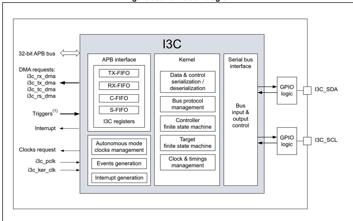
The block diagram illustrates the internal architecture of the I3C block. It is divided into three main functional blocks: APB interface, Kernel, and Serial bus interface.
- APB interface:
- Connects to a 32-bit APB bus.
- Contains TX-FIFO, RX-FIFO, C-FIFO, S-FIFO, and I3C registers.
- Receives DMA requests: i3c_rx_dma, i3c_tx_dma, i3c_tc_dma, and i3c_rs_dma.
- Receives Triggers (1) .
- Generates an Interrupt.
- Receives a Clocks request.
- Receives i3c_pclk and i3c_ker_clk inputs.
- Kernel:
- Contains Data & control serialization / deserialization, Bus protocol management, Controller finite state machine, Target finite state machine, and Clock & timings management.
- Serial bus interface:
- Contains Bus input & output control.
- Connects to GPIO logic blocks.
- GPIO logic blocks connect to external pins I3C_SDA and I3C_SCL.
1. Refer to Section 49.3.4: I3C triggers .
49.5 I3C pins and internal signals
Table 537. I3C input/output pins
| Pin name | Pin type | Description |
|---|---|---|
| I3C_SDA | Input/output | Serial bus data line |
| I3C_SCL | Input/output | Serial bus clock line |
Table 538. I3C internal input/output signals
| Signal name | Signal type | Description |
|---|---|---|
| i3c_pclk | I | APB clock |
| i3c_ker_clk | I | Kernel clock (also named as I3CCLK) |
| i3c_pclk_req | O | APB clock request |
| i3c_ker_clk_req | O | Kernel clock request |
| i3c_it (1) | O | Global interrupt line |
| Signal name | Signal type | Description |
|---|---|---|
| i3c_err_it (1) | O | Error interrupt line |
| i3c_evt_it (1) | O | Event interrupt line |
| i3c_rx_dma | O | DMA request for reading received bytes/words from RX-FIFO |
| i3c_tx_dma | O | DMA request for writing to be transmitted bytes/words to TX-FIFO |
| i3c_tc_dma | O | DMA request for writing to be transmitted control words to C-FIFO, when the I3C peripheral acts as controller |
| i3c_rs_dma | O | DMA request for reading status words from S-FIFO, when the I3C peripheral acts as controller |
1. Refer to Section 49.3.5: I3C interrupt(s) .
49.6 I3C reset and clocks
49.6.1 I3C reset
On a system reset, the I3C peripheral is reset.
Alternatively, the software can reset specifically the I3C peripheral by writing the corresponding reset control bit (I3CxRST) of the reset and clock controller (RCC). Refer to the RCC section of this document for more details.
Additionally, when acting as target, the enabled I3C peripheral (EN = 1 in the I3C_CFGR register) can receive an in-band reset pattern on the I3C bus from the controller. The software is then notified (when RSTF = 1 in the I3C_EVR register and/or the corresponding interrupt is enabled) to perform the requested action, as registered in RSTACT[1:0] of the I3C_DEVR0 register, on the former reception of the broadcast or direct RSTACT CCC. Refer to Table 542 and Section 49.16.16 for more details.
This reset interrupt notification can be used to wake up from a low power mode. For more details about the corresponding low-power mode(s), refer to the power management in the PWR section.
49.6.2 I3C clocks and requirements
As indicated in Figure 660 , the I3C peripheral is implemented with several clock domains:
- • SCL bus clock: for the I3C bus interface
- – When controller: the user must set and can adjust SCL/SDA timings by programming I3C timing register 0 (I3C_TIMINGR0) , I3C timing register 1 (I3C_TIMINGR1) and I3C timing register 2 (I3C_TIMINGR2) , as summarized in Controller initialization and Updating the configuration for a transfer, as controller .
- – When target: the user must set and comply with the bus available condition ( \( t_{AVAL} \) for an in-band interrupt or controller-role request), and the bus idle condition ( \( t_{IDLE} \) for a hot-join request), by programming I3C timing register 1 (I3C_TIMINGR1) , as summarized in Target initialization .
- • I3CCLK kernel clock: for the I3C protocol management, data and control serialization/deserialization, controller and target finite state machines, bus clock and timings management
- • APB clock: for the APB interface, DMA interface, events, and interrupt generation
APB clock and kernel clocks are driven from independently programmed clock sources via the RCC (refer to section Reset and clock control (RCC) for more details).
I3C kernel clock requirement, as controller
According to the intended value of the SCL clock on the bus, the application must guarantee that the frequency of the I3CCLK kernel clock be at least 2x the frequency of the SCL clock
Note: Sustaining \( F_{SCL\ max} = 12.9 \) MHz means a frequency of the I3CCLK kernel clock \( > 25.8 \) MHz.
I3C kernel clock requirements, as target
According to the intended value of the SCL clock on the bus, the application must guarantee a minimum operating frequency for the I3CCLK kernel clock, meeting the following constraints:
- 1. Period of the I3CCLK kernel clock
\(
< t_{HIGH}
\)
(SCL clock high period)
- – \( t_{HIGH\ min} = 24 \) ns. A frequency higher than 41.7 MHz guarantees this constraint, which can be relaxed, depending on the I3C bus/controller
- 2. Period of the I3CCLK kernel clock
\(
< t_{CASr}
\)
(clock after repeated start condition)
- – \( t_{CASr\ min} = t_{CAS\ min} / 2 = 19.2 \) ns. A frequency higher than 52 MHz guarantees this constraint, which can be relaxed, depending on the I3C bus/controller
- 3. Two periods of the I3CCLK kernel clock
\(
< t_{LOW\_OD}
\)
(SCL clock low period in open drain)
- – \( t_{LOW\_OD\ min} = 200 \) ns. A frequency higher than 10 MHz guarantees this constraint, which can be relaxed, depending on the I3C bus/controller
- 4. Frequency of the I3CCLK kernel clock
\(
> 2.5x
\)
frequency of the SCL clock
- – \( F_{SCL\ max} = 12.9 \) MHz. A frequency higher than 32.3 MHz guarantees this constraint, which can be relaxed, depending on the I3C controller
Note:
APB clock requirement
According to the intended value of the SCL clock on the bus, the application must guarantee a minimum operating frequency for the APB clock:
APB clock period \( < 3x \) (SCL clock period) - I3CCLK kernel clock period
This means that \( F_{APB} > [F_{SCL} \times F_{I3CCLK} / (3 \times F_{I3CCLK} - F_{SCL})] \)
Note: This equation can be simplified to a minimum value of 5 MHz for the APB frequency.
49.7 I3C peripheral state and programming
49.7.1 I3C peripheral state
The I3C peripheral plays the role of I3C bus controller, or the role of an I3C target. In any case (see Figure 661 and Figure 662 ), the peripheral is in one of the following states:
- • Disabled state:
- – After an I3C reset (system reset or I3C reset from RCC), the I3C peripheral is in disabled state.
- – When the software sets to 1 bit EN in the I3C_CFGFR register, the I3C peripheral takes into account the value of the different initialized configuration registers, and switches to the (enabled and) idle state. The peripheral is initialized as I3C target or I3C controller.
- – As I3C controller, then software can enable the I3C peripheral and initialize the I3C bus.
- – As I3C target, then the software can enable the I3C peripheral to operate on an I3C bus.
- • Idle state:
- – After being enabled (EN = 1), the I3C peripheral activates its I3CCLK and SCL clock domains, and is able to communicate on the I3C bus.
- – The software can partly update the I3C peripheral configuration, see Updating the configuration for a transfer, as controller and Updating the configuration of the I3C peripheral, as target for more details.
- – The I3C peripheral switches to the (enabled and) active state in either one of the following conditions:
Once the software initiates a transfer (as controller: when the software initiates a frame transfer; as target: when the software initiates an IBI/CR/HJ request).
Once the hardware receives a request from another I3C device on the bus (as controller: after a start request from a target and a maximum \( T_{CAS} \) time; as target: when receiving a broadcast/direct CCC or a private read/write).
- • Active state:
- – The I3C peripheral executes the transfer(s) on the bus.
- – When the requested transfer(s) is(are) completed, the software is notified by an event from the I3C event register (I3C_EVR) , and the corresponding interrupt is enabled by I3C interrupt enable register (I3C_IER) . The I3C peripheral switches to idle state, is still able to communicate on the bus, and can be (partly) reconfigured:
As controller: the raised event/flag can be frame completed (FCF), IBI/controller-role/hot-join request completed (IBIF/CRF/HJF), or transfer error (ERRF).
As target: the raised event/flag can be dynamic address assignment completed (DAUPDF), IBI completed (IBIENDF), controller-role gaining completed (CRUPDF), broadcast/direct CCC completed (xxUPDF/RSTF/GETF/STAF), private read/write completed (FCF), or transfer error (ERRF).
Note: The software can disable the I3C peripheral (write EN = 0), partially resetting it (subparts within the SCL clock domain and the I3CCLK kernel clock domain). Event, interrupt, and clock request generation are also impacted. The previously written configuration of the APB registers is kept and not modified.
49.7.2 I3C controller state and programming sequence
Figure 661 illustrates the overall programming sequence of the I3C peripheral acting as (primary) controller, including state transitions, main subtasks, and conditions, as explained in this section.
Figure 661. I3C (primary) controller state and programming sequence diagram
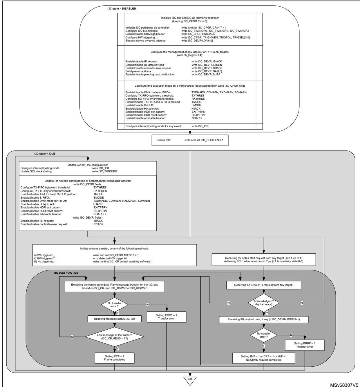
I3C state = DISABLED
Initialize I3C bus and I3C as (primary) controller (keeping I3C_CFGREN = 0):
- Initialize I3C peripheral as controller: write and set I3C_CFGR_CRINIT = 1
- Configure I3C bus timings: write I3C_TIMINGR0, I3C_TIMINGR1, I3C_TIMINGR2
- Enable/disable SDA high keeper: write I3C_CFGR_HKSDAEN
- Configure HW triggering 1 : write I3C_CFGR_TRIGHWEN, TRIGPOL, TRIGSEL[3:0]
- Set own device dynamic address: write I3C_DEVR0.DA[6:0]
Configure the management of any target i, for i = 1 to nb_targets: (with nb_targets ≤ 4):
- Enable/disable IBI request: write I3C_DEVRI.IBIACK
- Enable/disable IBI data payload: write I3C_DEVRI.IBIDEN
- Enable/disable controller-role request: write I3C_DEVRI.CRACK
- Set dynamic address: write I3C_DEVRI.DA[6:0]
- Enable/disable pending read notification: write I3C_DEVRI.SUSP
Configure (the execution mode of) a frame/target-requested transfer: write I3C_CFGR fields
- Enable/disable DMA mode for FIFOs: TXDMAEN, CDMAEN, RXDMAEN, SDMAEN
- Configure TX-FIFO byte/word threshold: TXTHRES
- Configure RX-FIFO byte/word threshold: RXTHRES
- Enable/disable TX-FIFO and C-FIFO preload: TMODE
- Enable/disable S-FIFO: SMODE
- Enable/disable Hot-join Ack: HJACK
- Enable/disable HDR exit pattern: EXITPTRN
- Enable/disable HDR reset pattern: RSTPTRN
- Enable/disable arbitrable header: NOARBH
Configure interrupt/polling mode for any event: write I3C_IER
Enable I3C: write and set I3C_CFGREN = 1
I3C state = IDLE
Configure interrupt/polling mode: Update (or not) the configuration: write I3C_IER
Update SCL clock stalling: write I3C_TIMINGR2
Update (or not) the configuration of a frame/target-requested transfer: write I3C_CFGR fields:
- Configure TX-FIFO byte/word threshold: TXTHRES
- Configure RX-FIFO byte/word threshold: RXTHRES
- Enable/disable TX-FIFO and C-FIFO preload: TMODE
- Enable/disable S-FIFO: SMODE
- Enable/disable DMA mode for FIFOs: TXDMAEN, CDMAEN, RXDMAEN, SDMAEN
- Enable/disable Hot-join Ack: HJACK
- Enable/disable HDR exit pattern: EXITPTRN
- Enable/disable HDR reset pattern: RSTPTRN
- Enable/disable arbitrable header: NOARBH
Enable/disable IBI request: write I3C_DEVRI fields: IBIACK
Enable/disable controller-role request: CRACK
Initiate a frame transfer, by any of the following methods:
- SW-triggered 1 : write and set I3C_CFGR_TSFSET = 1
- HW-triggered 1 : on a detected HW trigger bit: write the first I3C_CR control word (by software)
- No triggering:
Receiving (or not) a start request from any target (i = 1 up to 4) Activating SCL before a maximum T us (c.f. bus activity state 0-3)
I3C state = ACTIVE
Executing the control (and data, if any) message transfer on the I3C bus based on I3C_CR, and I3C_TD(W)R or I3C_RD(W)R
No transfer error? (Y/N)
Last message of the frame? (I3C_CR.MEND = 1?)
Setting FCF = 1 Frame completed
Setting ERRF = 1 Transfer error
Receiving an IBICRHJ request from any target i
Acknowledged? (by hardware) (Y/N)
Receiving IBI payload data, if any (if I3C_DEVRI.IBIDEN=1)
No transfer error? (Y/N)
Setting IBIF = 1 or CRF = 1 or HJF = 1 IBI/CR/HJ request completed
Setting ERRF = 1 Transfer error
End
MSV68307V5
1. This feature is implementation-dependent and can be unavailable. Refer to Section 49.3.4: I3C triggers .
Controller initialization
When the controller is in disabled state (EN = 0 in the I3C_CFGR register), the software must initialize as follows:
- • Configure
I3C configuration register (I3C_CFGR)
with the following fields:
- – CRINIT = 1: as I3C bus controller
- – HKSDAEN: high keeper on SDA enable/disable
- • Configure I3C bus timings:
- a)
I3C timing register 0 (I3C_TIMINGR0)
:
- – SCL clock high time period ( \( t_{DIG\_H} \) , \( t_{DIG\_H\_MIXED} \) ) in legacy I 2 C and I3C open-drain/push-pull
- – SCL clock low time period ( \( t_{DIG\_L} \) , \( t_{DIG\_OD\_L} \) ) in legacy I 2 C and I3C open-drain/push-pull
- b)
I3C timing register 1 (I3C_TIMINGR1)
:
- – SDA hold time in push-pull ( \( t_{HD\_PP} \) )
- – bus free condition time (I3C \( t_{CAS} \) , legacy I 2 C \( t_{BUF} \) )
- – I3C repeated start timing ( \( t_{CASr} \) , \( t_{CBSr} \) )
- – I3C stop timing ( \( t_{CBP} \) )
- – SCL clock low maximum stalling on the ENTDAA CCC ( \( t_{STALLDAA} \) ), or on the ACK/NACK of a legacy I 2 C or address phase of an I3C transfer, or the parity bit of a write data transfer, or on the ACK/NACK data phase of a legacy I 2 C write, or on the transition bit of an I3C read transfer, or on the ACK/NACK phase of a legacy I 2 C write ( \( t_{STALL} \) ), to adjust SCL clock low stalling, if needed by the I3C peripheral itself, when used as controller
- – \( t_{NEWCRLock} \) for controller-role hand-off procedure (after GETACCCR CCC)
- c)
I3C timing register 2 (I3C_TIMINGR2)
:
- – SCL clock low stalling time, with separated enable/disable for each phase, to adjust SCL clock low stalling, if needed on the SDA hand-off with the addressed I3C target or legacy I 2 C target
- a)
I3C timing register 0 (I3C_TIMINGR0)
:
- • Configure its own dynamic address: DA [6:0] field of the I3C own device characteristics register (I3C_DEVR0)
- • Configure the management of any device target x: I3C device x characteristics register (I3C_DEVRx) , for x = 1 to x ≤ 4
- • Configure the execution mode of a frame transfer or a target-requested transfer:
I3C configuration register (I3C_CFGR)
, with the following fields:
- – TXDMAEN, CDMAEN, RXDMAEN, SDMAEN: DMA mode enable/disable for respectively, TX-FIFO, C-FIFO, RX-FIFO, S-FIFO
- – TXTHRES, RXTHRES: respectively TX-FIFO and RX-FIFO byte/world threshold
- – TMODE: transmit mode (enable/disable for both TX-FIFO and C-FIFO preload)
- – SMODE: S-FIFO enable/disable
- – EXITPTRN, RSTPTRN: exit, reset pattern enable/disable
- – HJACK: hot-join acknowledge enable/disable
- – NOARBH: arbitrable header disable/enable
- • Configure interrupt generation or polling mode from any event: I3C interrupt enable register (I3C_IER)
Then, the software can enable the I3C peripheral (set EN = 1).
Note: The software can write once all the fields of the I3C_CFGR while enabling it.
Start a controller-initiated frame transfer
When the controller is in enabled state (EN = 1 in the I3C_CFGR register), the software can initiate a frame transfer by any of the following configuration methods:
- • Software-triggering: on a write and set TSFSET = 1 in the I3C_CFGR register
- – This causes the hardware to raise the flag CFNFF = 1 in the I3C_EVR register, to request a first control word I3C_CR to be written.
- • No triggering: on a write of the first control word I3C_CR by software.
Then, regardless of the frame starting method, the I3C peripheral switches to active state. While the control word is not the last message of the I3C frame (while MEND = 0 in the I3C_CR register), and while there is no transfer error (while ERRF = 1 in the I3C_EVR register), the hardware keeps requesting a next control word, and continuing the frame transfer:
- • If the C-FIFO is not configured in DMA mode (CDMAEN = 0 in the I3C_CFGR register), the software writes a next control word following the flag CFNFF = 1 in the I3C_EVR register, or the corresponding interrupt if enabled (if CFNFIE = 1 in I3C_IER register)
- • If the C-FIFO is configured in DMA mode (CDMAEN = 1), a next control word is automatically pushed and written by the allocated DMA channel consequently to the asserted I3C DMA request (i3c_tc_dma).
Start and receiving a target-initiated transfer
When the controller is in enabled state (EN = 1 in the I3C_CFGR register), concurrently to a possible controller-initiated transfer, a target can initiate a transfer by issuing a start request (drive SDA low), provided the controller has allowed a hot-join request, an IBI request, or a controller-role request via the I3C_DEVR0 register.
In this case, even though the controller software has no intent to start a frame transfer, the hardware switches to active state (activates the SCL clock before a maximum \( t_{CAS} \) time defined as 1 µs, 100 µs, 2 ms, or 50 ms, depending on, respectively, the bus activity state 0, 1, 2, or 3) to receive the hot-join/in-band interrupt/controller-role request from the target.
For more information about the execution of target-initiated I3C bus transfer and its related programming as a controller, refer to the relevant figures in Section 49.9 :
- • Figure 673: IBI transfer, as controller/target
- • Figure 674: Hot-join request transfer, as controller/target
- • Figure 675: Controller-role request transfer, as controller/target
Executing a (controller-initiated) frame transfer
The controller executes on the bus the frame transfer until the completion of the last message (FCF = 1 in the I3C_EVR register), or a transfer error (ERRF = 1 in the I3C_EVR register), and the corresponding interrupt, if enabled. This is based on I3C_CR and I3C_TD(W)R registers, written explicitly by software or pushed by the allocated DMA channel, and based on the I3C_RD(W)R, read explicitly by the software or by the allocated DMA channel. Then the I3C controller switches back to idle state.
For more information about the execution of controller-initiated I3C bus transfer and its related programming as a controller, refer to figures in Section 49.9 :
- • Figure 663: I3C CCC messages, as controller
- • Figure 664: I3C broadcast ENTDAA CCC, as controller
- • Figure 665: I3C broadcast, direct read and direct write RSTACT CCC, as controller
- • Figure 670: I3C private read/write messages, as controller
- • Figure 672: Legacy I2C read/write messages, as controller
Figure 661 does not include the management of the FIFOs (TX-FIFO, RX-FIFO, C-FIFO, and S-FIFO). This is detailed in Section 49.10 .
For each completed message without transfer error, the hardware reports the exchanged transfer on the I3C bus by updating I3C status register (I3C_SR) , which can be read or not by the software when the S-FIFO is disabled (SMODE = 0 in the I3C_CFGR register).
- • In the case of a direct CCC read or a private read transfer, in addition to the completion of the last message (FCF = 1 in the I3C_EVR register) or a transfer error (ERRF = 1 in the I3C_EVR register) and the corresponding interrupt if enabled, and provided that the S-FIFO is disabled for the status register I3C_SR (SMODE = 0 in the I3C_CFGR register), the software is notified if the read transfer is ended prematurely by the target by RXTGTENDF = 1 in the I3C_EVR register, and the corresponding interrupt, if enabled. The software can then read I3C_SR, to get more information about the executed transfer.
Alternatively, if the S-FIFO is enabled (SMODE = 1 in the I3C_CFGR register), the status register I3C_SR must be read for each executed message, either directly by the software (notified by SFNEF = 1 in the I3C_EVR register and the corresponding interrupt, if enabled), or via the DMA (if SDMAEN = 1 in the I3C_CFGR register), no matter if a read is prematurely ended by the target or not. Frame completion (FCF = 1 in the I3C_EVR register) occurs only after reading the status of the last message (S-FIFO is empty). For more information, refer to Section 49.10.4 .
Updating the configuration for a transfer, as controller
Back in idle state, the software can update the configuration of the I3C peripheral before the next transfer:
- • Modify SCL clock stalling via I3C timing register 2 (I3C_TIMINGR2)
- • Modify the interrupt/polling mode policy via I3C interrupt enable register (I3C_IER)
- • Modify the following fields of the
I3C configuration register (I3C_CFGR)
:
- – TXTHRES, RXTHRES
- – TMODE, SMODE
- – TXDMAEN, CDMAEN, RXDMAEN, SDMAEN
- – EXITPTRN, RSTPTRN
- – NOARBH
- • Modify/prepare the control words, status words, read/write data of the next frame transfer to be executed, by software and/or DMA
- – I3C message control register (I3C_CR), I3C message control register [alternate] (I3C_CR)
- – I3C status register (I3C_SR)
- – I3C transmit data byte register (I3C_TDR), I3C transmit data word register (I3C_TDWR)
- – I3C receive data byte register (I3C_RDR), I3C receive data word register (I3C_RDWR)
- • Typically after having issued and completed a broadcast/direct DISEC/ENEC CCC:
- – Modify the hot-join acknowledge policy via bit HJACK in the I3C_CFGR register
- – Modify IBI/CR acknowledge policy to any target x, via I3C device x characteristics register (I3C_DEVRx)
The registers usage versus the I3C peripheral role as controller is summarized in Section 49.8.1 .
The static/dynamic registers fields usage when acting as controller is summarized in Table 540 .
49.7.3 I3C target state and programming sequence
Figure 662 illustrates the overall programming sequence of the I3C peripheral acting as target, including state transitions, main subtasks, and conditions, as explained in this section.
Figure 662. I3C target state and programming sequence diagram
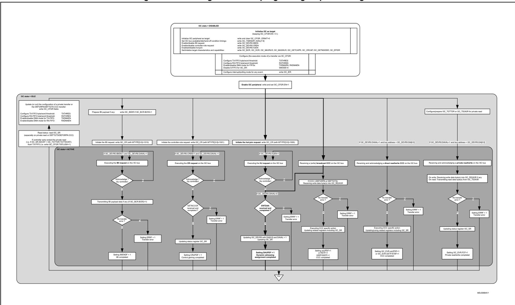
I3C state = DISABLED
- Initialize I3C as target (keeping I3C_CFSR.EN = 0).
- Initialize I3C peripheral as target:
- Set I3C bus availability/detachment condition settings: write and clear I3C_CFGR.CRINT=0
- Enable/disable IB request: write I3C_TAMSR.ANAVL[0]
- Enable/disable controller role request: write I3C_DEVIRD.IBEN
- Enable/disable target: write I3C_DEVIRD.CREN
- Enable/disable hot-plug: write I3C_DEVIRD.HEN
- Set I3C bus availability/detachment condition settings: write I3C_EOR.IGL, I3C_DEVIRD.MAWXR, I3C_DEVIRD.MAWXR, I3C_GETCAPR, I3C_CRCP, I3C_GETMDR, I3C_EPIDR
- Configure the execution mode of a transfer via I3C_CFGR:
- Configure TX-FIFO watermark threshold: TXTHRES
- Configure RX-FIFO watermark threshold: RXTHRES
- Enable/disable DMA mode for TX-FIFO: TXDMAEN, RXDMAEN
- Disable S-FIFO for I3C_SR: SMODE=0
- Configure interrupt/spoofing mode for any event: write I3C_ER
Enable I3C peripheral: write and set I3C_CFGR.EN=1
I3C state = IDLE
- Update (or reset) the configuration of a private transfer or the DEFUPA/DEFTOTS/CCC transfer: write I3C_CFGR.RAITS
- Configure TX-FIFO watermark threshold: TXTHRES
- Configure RX-FIFO watermark threshold: RXTHRES
- Enable/disable DMA mode for TX-FIFO: TXDMAEN, RXDMAEN
- Read status: read I3C_SR (especially on private read or DEFTOTS/DEFGRP.CCC) (i.e. if I3C_SR.RCNT = I3C_TOTDR.TOTDRN): flush TX-FIFO (i.e. write I3C_CFGR.TXFLUSH=1)
Preparation for transfer:
- Prepare IB payload if any: write I3C_IBDR if I3C_IBCR.BCR=1
- Initiate the IB request with I3C_CR (with MTYP[3:0]=1010)
- Initiate the controller role request with I3C_CR (with MTYP[3:0]=1001)
- Initiate the hot-plug request with I3C_CR (with MTYP[3:0]=1000)
- Configure/prepare I3C_TOTDR or I3C_TDWR for private read
I3C state = ACTIVE
- IB request path:
- If I3C_DEVIRD.IBEN=1 and I3C_DEVIRD.DAVAL=1: Executing the IB request on the I3C bus → Acknowledge? (by controller) → No transfer error? → Transmitting IB payload data if any (if I3C_IBCR.BCR=1) → No transfer error? → Setting IBENDF = 1 (IB completed)
- Else: Setting ERRIF = 1 (Transfer error)
- Controller role request path:
- If I3C_DEVIRD.CREN=1 and I3C_DEVIRD.DAVAL=1: Executing the CR request on the I3C bus → Acknowledge? (by controller) → SETACCR received and completed? → Updating status register I3C_SR → Setting CRRUPF = 1 (Control pairing completed)
- Else: Setting ERRIF = 1 (Transfer error)
- Hot-plug request path:
- If I3C_DEVIRD.HEN=1: Executing the NUT request on the I3C bus → Acknowledge? (by controller) → ENTAA received and completed? → Updating I3C_DEVIRD.DAVAL and DAVAL=1 → Updating I3C_SR → Setting DAUPF = 1 (Dynamic addressing assignment completed)
- Else: Setting ERRIF = 1 (Transfer error)
- Broadcast CCC path:
- Receiving a (only) broadcast CCC on the I3C bus → If CCC=0xDE/0F/0A or DEFTOTS: Receiving write data bytes into I3C_RDWR → No transfer error? → Executing CCC specific action: Updating related registers including I3C_SR → Setting xALLPF=1 or RSTP=1 (GENR/GETP=1 CCC completed)
- Else: Setting ERRIF = 1 (Transfer error)
- Direct read/write CCC path:
- Receiving and acknowledging a direct read/write CCC on the I3C bus → No transfer error? → Executing CCC specific action: Updating related registers including I3C_SR → Setting I3C_EVR.FCF=1 or I3C_EVR.GETP/STAF=1 (CCC completed)
- Else: Setting ERRIF = 1 (Transfer error)
- Private read/write path:
- Receiving and acknowledging a private read/write on the I3C bus → On read: Transmitting read data bytes from I3C_TDWR if any → No transfer error? → Updating status register I3C_SR → Setting I3C_EVR.FCF=1 (Private read/write completed)
- Else: Setting ERRIF = 1 (Transfer error)
End of sequence
Target initialization
When the target is in disabled state (EN = 0 in the I3C_CFGR register), the software must initialize as follows:
- • Set the I3C peripheral as target: write and clear CRINIT = 0 in the I3C_CFGR register
- • Set the I3C bus timings via
I3C timing register 1 (I3C_TIMINGR1)
: write AVAL[7:0] for:
- – Bus available condition time ( \( t_{\text{AVAL}} \) ) for IBI or controller-role request
- – Bus idle condition time ( \( t_{\text{IDLE}} \) ) for hot-join request
- – \( t_{\text{NEWCRLock}} \) for controller-role hand-off procedure (after GETACCCR CCC)
- • Configure target-initiated requests: write
I3C own device characteristics register (I3C_DEVR0)
with
- – IBIEN: in-band interrupt (also known as IBI) request enable/disable
- – CREN: controller-role request enable/disable
- – HJEN: hot-join request enable/disable
- • Initialize target characteristics and capabilities: write
- – I3C bus characteristics register (I3C_BCR)
- – I3C device characteristics register (I3C_DCR)
- – I3C maximum read length register (I3C_MAXRLR)
- – I3C maximum write length register (I3C_MAXWLR)
- – I3C get capability register (I3C_GETCAPR)
- – I3C controller-role capability register (I3C_CRCAPR)
- – I3C get max data speed register (I3C_GETMXDSR)
- – I3C extended provisioned ID register (I3C_EPIDR)
- • Configure the execution mode of a transfer:
I3C configuration register (I3C_CFGR)
, with the following fields:
- – TXDMAEN, RXDMAEN: DMA mode enable/disable for, respectively, TX-FIFO and RX-FIFO
- – TXTHRES, RXTHRES: respectively TX-FIFO and RX-FIFO byte/world threshold
- – Disable S-FIFO: SMODE = 0 (default/reset value)
- • Configure interrupt generation or polling mode from any event: I3C interrupt enable register (I3C_IER)
Then, the software can enable the I3C peripheral (write and set EN = 1).
Note: The software can write once all the fields of the I3C_CFGR register while enabling it.
Receiving a (broadcast CCC, direct read/write CCC or private read/write) message on the I3C bus
When the target is in idle state (EN = 1 in the I3C_CFGR register), the target is ready to receive a communication message on the I3C bus from the controller, and is ready to switch to the active state.
Typically, first, the active target is receiving a broadcast ENTDAA CCC, possibly after optional received broadcast ENEC/DISEC CCC(s), and is then assigned a dynamic address. The event DAUPF in the I3C_EVR register is raised to 1, the related interrupt is generated if enabled, and the target goes back to idle state.
After that, the idle target is ready to receive any other broadcast CCC message, or direct read/write CCC, or private read/write message from the controller.
For more information about the execution of controller-initiated I3C bus transfers and its related programming as a target, including the updated I3C registers and fields, refer to figures in Section 49.9 :
- • Figure 666: I3C CCC messages, as target
- • Figure 667: I3C broadcast ENTDAA CCC, as target
- • Figure 668: I3C broadcast DEFTGTS CCC, as target
- • Figure 669: I3C broadcast DEFGRPA CCC, as target
- • Figure 671: I3C private read/write messages, as target
Figure 662 does not include the FIFOs management (TX-FIFO, RX-FIFO). This is detailed in Section 49.10 .
Read the message status register
For each received and completed message without transfer error, the hardware reports the exchanged transfer on the bus by updating the I3C status register (I3C_SR) , which can be read by the software after being notified by the corresponding flag in the I3C event register (I3C_EVR) , or by the corresponding interrupt if enabled in the I3C interrupt enable register (I3C_IER) .
I3C status register (I3C_SR) must be read by the software after the following messages:
- • A private read: to get the number of exchanged data bytes, as the controller can have ended the transfer earlier than expected by the target (if XDCNT[15:0] in the I3C_SR register is lower than TGTDCNT[15:0] in the I3C_TGTDR register). If so, software must flush the TX-FIFO (write TXFLUSH = 1 in the I3C_CFGR register).
- • A DEFTGTS CCC or a DEFGRPA CCC: to get the number of received data bytes in the RX-FIFO
Start a (target-initiated) transfer on the I3C bus
When the target goes first from disabled to idle state (software writes EN = 1 in the I3C_CFGR register), concurrently to be able to receive a broadcast CCC from the controller, the software can initiate a hot-join request (the software writes MTYPE[3:0] = 1000 in the I3C_CR register) to be eligible to participate to a next ENTDAA CCC, provided it is allowed to do so (HJEN = 1 in the I3C_DEVR0 register).
Once a dynamic address is assigned (DAUPF = 1 in the I3C_EVR register), more generally and possibly concurrently to a frame transfer emitted by the controller, the software can initiate an IBI (in-band interrupt request) to the controller, or a controller-role request by writing the related control word into the I3C_CR register.
For more information about the execution of target-initiated I3C bus transfer, and its related programming as a target, refer to figures in Section 49.9 :
- • Figure 673: IBI transfer, as controller/target
- • Figure 674: Hot-join request transfer, as controller/target
- • Figure 675: Controller-role request transfer, as controller/target
Updating the configuration of the I3C peripheral, as target
Back in idle state, the software can update the configuration of the I3C target before a next transfer:
- • Modify the interrupt/polling mode policy via I3C interrupt enable register (I3C_IER)
- • Modify following fields of the
I3C configuration register (I3C_CFGR)
:
- – TXTHRES, RXTHRES
- – TXDMAEN, RXDMAEN
- • Modify/prepare the I3C IBI payload data register (I3C_IBIDR) , if any payload (if BCR2 = 1 in the I3C_BCR register), before initiating an IBI transfer (write I3C message control register [alternate] (I3C_CR) with MTYPE[3:0] = 1010)
- • Modify/prepare I3C target transmit configuration register (I3C_TGTTDR) , to disable or enable the TX-FIFO to be preloaded with a defined number of data bytes to be transmitted, before receiving a private read or a direct CCC read (out of the GETSTATUS CCC)
The registers usage vs. the I3C peripheral role as target is summarized in Section 49.8.1 .
The static/dynamic registers fields usage, when acting as target, is summarized in Table 541 .
49.8 I3C registers and programming
49.8.1 I3C register set, as controller/target
Table 539 lists the registers and their usage versus the I3C peripheral role.
Table 539. I3C register usage
| Register | Used as controller | Used as target |
|---|---|---|
| I3C_CR | X | X |
| I3C_CFGR | X | X |
| I3C_RDR | X | X |
| I3C_RDWR | X | X |
| I3C_TDR | X | X |
| I3C_TDWR | X | X |
| I3C_IBIDR | X | X |
| I3C_TGTTDR | - | X |
| I3C_SR | X | X |
| I3C_SER | X | X |
| I3C_RMR | X | X |
| I3C_EVR | X | X |
| I3C_IER | X | X |
| I3C_CEVR | X | X |
| I3C_DEVR0 | X | X |
Table 539. I3C register usage (continued)
| Register | Used as controller | Used as target |
|---|---|---|
| I3C_DEVRx (x = 1 to 4) | X | - |
| I3C_MAXRLR | - | X |
| I3C_MAXWLR | - | X |
| I3C_TIMINGR0 | X | - |
| I3C_TIMINGR1 | X | X |
| I3C_TIMINGR2 | X | - |
| I3C_BCR | - | X |
| I3C_DCR | - | X |
| I3C_GETCAPR | - | X |
| I3C_CRCAPR | - | X |
| I3C_GETMXDSR | - | X |
| I3C_EPIDR | - | X |
49.8.2 I3C registers and fields use versus peripheral state, as controller
When the I3C peripheral acts as controller, Table 540 lists the registers and their usage versus the controller state (disabled, idle, and active).
Table 540. I3C registers/fields usage versus controller state
| Register | Used as controller | Writable only in disabled state | Typically written/read in idle state | Typically written/read in idle or active state |
|---|---|---|---|---|
| I3C_CR | X | - | - | X |
Table 540. I3C registers/fields usage versus controller state (continued)
| Register | Used as controller | Writable only in disabled state | Typically written/read in idle state | Typically written/read in idle or active state |
|---|---|---|---|---|
| I3C_CFGR | X | CRINIT HKSDAEN EN (1) | Write: any used field except {CRINIT, HKSDAEN}, namely {CDMAEN SDMAEN TXDMAEN RXDMAEN TMODE SMODE TXTHRES RXTHRES HJACK EXITPTRN RSTPTRN NOARBH} (2) CFLUSH SFLUSH TXFLUSH RXFLUSH TSFSET | - |
| I3C_RDR | X | - | - | Read |
| I3C_RDWR | X | - | - | Read |
| I3C_TDR | X | - | - | Write |
| I3C_TDWR | X | - | - | Write |
| I3C_IBIDR | X | - | - | Read |
| I3C_TGTTDR | - | |||
| I3C_SR | X | - | - | Read |
| I3C_SER | X | - | Read | - |
| I3C_RMR | X | - | - | Read RADD[6:0] IBIRDCNT[2:0] |
Table 540. I3C registers/fields usage versus controller state (continued)
| Register | Used as controller | Writable only in disabled state | Typically written/read in idle state | Typically written/read in idle or active state |
|---|---|---|---|---|
| I3C_EVR | X | - | - | Read (controller-role fields): HJF CRF IBIF FCF ERRF RXTGTENDF RXFNEF TXFNFF SFNEF CFNFF RXLASTF TXLASTF TXFEF CFEF |
| I3C_IER | X | Write xIE with x = HJ, CR, IBI, FC, ERR, RXTGTEND, RXFNE, TXFNF, SFNE, CFNF (2) | ||
| I3C_CEVR | X | - | - | Write (controller-role fields, refer to I3C_EVR) |
| I3C_DEVR0 | X | Write DA[6:0] (2) | ||
| I3C_DEVRx x = 1..4 | X | Write SUSP, IBIDEN, IBIACK, CRACK, DA[6:0] (2) | ||
| I3C_MAXRLR | - | |||
| I3C_MAXWLR | - | |||
| I3C_TIMINGR0 | X | X | - | - |
| I3C_TIMINGR1 | X | X | - | - |
| I3C_TIMINGR2 | X | Write (2) | ||
| I3C_BCR | - | |||
| I3C_DCR | - | |||
| I3C_GETCAPR | - | |||
| I3C_CRCAPR | - | |||
| I3C_GETMXDSR | - | |||
| I3C_EPIDR | - | |||
1. Bit EN in the I3C_CFGR register is written and set in disabled state (when the same bit is 0). This field can be also written and de-asserted in idle state.
2. These fields are typically written and initialized in disabled state during bus configuration. They are not write-protected when EN = 0, and can be also written and updated in other state(s).
49.8.3 I3C registers and fields usage versus peripheral state, as target
When the I3C peripheral acts as target, Table 541 lists the registers and their usage versus the I3C target state (disabled, idle, and active).
Table 541. I3C registers/fields usage versus target state
| Register | Used as target | Writable only in disabled state | Typically written/read in idle state | Typically written/read in idle or active state |
|---|---|---|---|---|
| I3C_CR | X | - | MTYPE[3:0] DCNT[2:0] | - |
| I3C_CFGR | X | CRINIT EN (1) | Write: any used field except CRINIT, namely: {TXDMAEN RXDMAEN TXTHRES RXTHRES} (2) TXFLUSH RXFLUSH | - |
| I3C_RDR | X | - | - | Read |
| I3C_RDWR | X | - | - | Read |
| I3C_TDR | X | - | - | Write |
| I3C_TDWR | X | - | - | Write |
| I3C_IBIDR | X | - | Write | - |
| I3C_TGTTDR | X | - | Write | - |
| I3C_SR | X | - | - | Read DIR, XDCNT[15:0] |
| I3C_SER | X | - | Read DOVR, STALL, PERR, CODERR[3:0] | - |
| I3C_RMR | X | - | - | Read RCODE[7:0] |
Table 541. I3C registers/fields usage versus target state (continued)
| Register | Used as target | Writable only in disabled state | Typically written/read in idle state | Typically written/read in idle or active state |
|---|---|---|---|---|
| I3C_EVR | X | - | - | Read (target-role fields): GRPF DEFF INTUPDF ASUPDF RSTF MRLUPDF MWLUPDF DAUPDF STAF GETF WKPF CRUPDF IBIENDF ERRF FCF RXFNEF TXFNFF TXLASTF TXFEF |
| I3C_IER | X | Write xIE with x = GRP, DEF, INTUPD, ASUPD, RST, MRLUPD, MWLUPD, DAUPD, STA, GET, WKP, CRUPD, IBIEND, ERR, FC, RXFNE, TXFNF (2) | ||
| I3C_CEVR | X | - | - | Write (target-role fields, refer to I3C_EVR) |
| I3C_DEVR0 | X | HJEN CREN IBIEN | Read RSTVAL, RSTACT[1:0], and AS[1:0] | - |
| I3C_DEVRx x = 1..4 | - | |||
| I3C_MAXRLR | X | X | - | - |
| I3C_MAXWLR | X | X | - | - |
| I3C_TIMINGR0 | - | |||
| I3C_TIMINGR1 | X | AVAL[7:0] | - | - |
| I3C_TIMINGR2 | - | |||
| I3C_BCR | X | X | - | - |
| I3C_DCR | X | X | - | - |
| I3C_GETCAPR | X | X | - | - |
| I3C_CRCAPR | X | X | - | - |
| Register | Used as target | Writable only in disabled state | Typically written/read in idle state | Typically written/read in idle or active state |
|---|---|---|---|---|
| I3C_GETMXDSR | X | X | - | - |
| I3C_EPIDR | X | X | - | - |
- 1. Bit EN in the I3C_CFGR register is written and set in disabled state (when the same bit is 0). This field can be also written and de-asserted in idle state.
- 2. These fields are typically written and initialized in disabled state during I3C bus configuration. They are not write-protected when EN = 0.
49.9 I3C bus transfers and programming
49.9.1 I3C command set (CCCs), as controller/target
The list of the supported I3C command set (for example, list of CCCs, common command codes) and the overview of how they are handled by the I3C peripheral acting as controller or target, is specified in Table 542 .
Table 542. List of supported I3C CCCs, as controller/target
| CCC name | CCC value | Read /write | With/without defining byte With/without sub-command byte | With/without optional data byte(s) | Use as controller | Use as target, raised I3C_EVR event | When target: specific action |
|---|---|---|---|---|---|---|---|
| Broadcast CCCs | |||||||
| ENEC | 0x00 | Write | No defining/sub-command byte | With one data byte (enable target events byte) | X | X, INTUPDF | Update and enable I3C_DEVR0: HJEN, CREN, IBIEN if any |
| DISEC | 0x01 | With one data byte (disable target events byte) | X | X, INTUPDF | Update and disable I3C_DEVR0: HJEN, CREN, IBIEN if any | ||
| ENTASx x = 0...3 | 0x02 ... 0x05 | No data byte | X | X, ASUPDF | Update I3C_DEVR0.AS[1:0] | ||
| RSTDAA | 0x06 | - | X | X, DAUPDF | Clear I3C_DEVR0.DAVAL = 0 | ||
| ENTDAA | 0x07 | - | X | X, DAUPDF if DAVAL = 0 | Update I3C_DEVR0: DA[6:0] and set DAVAL = 1 | ||
| DEFTGTS | 0x08 | With [1+ 4x (1+ number_of_targets)] x data bytes | X | X, DEFF | Update I3C_RDR/ I3C_RDWR. Refer to Figure 668 . | ||
| SETMWL | 0x09 | With two data byte | X | X, MWLUPDF | Update I3C_MAXWLR | ||
| SETMRL | 0x0A | With 2 or 3 data bytes | X | X, MRLUPDF | Update I3C_MAXRLR | ||
| ENTTM | 0x0B | With one data byte | X | - | - | ||
| SETXTIME | 0x28 | With sub-command byte | Without or with one or more data bytes | X | - | - | |
| SETAASA | 0x29 | No defining/sub-command byte | No data byte | X | - | - | |
| RSTACT | 0x2A | With defining byte (0x00, 0x01 or 0x02) | X | X, RSTF after detected reset pattern | Update I3C_DEVR0: RSTACT[1:0] and set RSTVAL = 1 | ||
| DEFGRP | 0x2B | No defining/sub-command byte | With several data bytes | X | X, GRPF | Update I3C_RDR/ RDWR. Refer to Figure 669 . | |
| RSTGRP | 0x2C | No data byte | X | - | - | ||
Table 542. List of supported I3C CCCs, as controller/target (continued)
| CCC name | CCC value | Read /write | With/without defining byte With/without sub-command byte | With/without optional data byte(s) | Use as controller | Use as target, raised I3C_EVR event | When target: specific action |
|---|---|---|---|---|---|---|---|
| Direct CCCs | Action if ACK (if I3C target Address = I3C_DEVR0.DA[6:0] and I3C_DEVR0.DAVAL = 1) (else NACK) | ||||||
| ENEC | 0x80 | Write | No defining/sub-command byte | With one data byte (enable target events byte) | X | X, INTUPDF | Update and enable I3C_DEVR0: HJEN, CREN, IBIEN if any |
| DISEC | 0x81 | With one data byte (disable target events byte) | X | X, INTUPDF | Update and disable I3C_DEVR0: HJEN, CREN, IBIEN if any | ||
| ENTASx x = 0...3 | 0x82.. ..0x85 | No data byte | X | X, ASUPDF | Update I3C_DEVR0.AS[1:0] | ||
| SETDASA | 0x87 | No data byte | X | - | - | ||
| SETNEWDA | 0x88 | With one data byte | X | X, DAUPDF if DAVAL = 1 | Update I3C_DEVR0: DA[6:0] (and keep DAVAL = 1) | ||
| SETMWL | 0x89 | With two data bytes | X | X, MWLUPDF | Update I3C_MAXWLR | ||
| SETMRL | 0x8A | With two or three data bytes | X | X, MRLUPDF | Update I3C_MAXRLR | ||
| GETMWL | 0x8B | Read | No defining/sub-command byte | With two data bytes | X | X, GETF | Return data bytes from I3C_MAXWLR[15:0]. Refer to Section 49.16.19 . |
| GETMRL | 0x8C | With two or three data bytes | X | X, GETF | Return data bytes from I3C_MAXRLR[15:0] and if I3C_BCR.BCR2 = 1 return third byte from I3C_MAXRLR.IBIP[2:0]. Refer to Section 49.16.18 . | ||
Table 542. List of supported I3C CCCs, as controller/target (continued)
| CCC name | CCC value | Read /write | With/without defining byte With/without sub-command byte | With/without optional data byte(s) | Use as controller | Use as target, raised I3C_EVR event | When target: specific action |
|---|---|---|---|---|---|---|---|
| GETPID | 0x8D | Read | No defining/sub-command byte | With six data bytes | X | X, GETF | Return data bytes from I3C_EPIDR. Refer to Section 49.16.28 . |
| GETBCR | 0x8E | With one data byte | X | X, GETF | Return data byte from I3C_BCR[7:0]. Refer to Section 49.16.23 . | ||
| GETDCR | 0x8F | X | X, GETF | Return I3C_DCR[7:0]. Refer to Section 49.16.24 . | |||
| GETSTATUS | 0x90 | With or without defining byte (TGTSTAT, PRECR) | With two data bytes (format 1 or format 2 with PRECR) | X | X, STAF if format 1 X, GETF if format 2 | Return 2 data bytes, as detailed in Section 49.9.9 . | |
| GETACCCR | 0x91 | No defining/sub-command byte | With one data byte | X | X, CRUPDF | Return data byte from I3C_DEVR0.DA[6:0] with parity bit | |
| GETMXDS | 0x94 | With or without defining byte (WRRDTURN, CRHDLY) | With two data bytes (format 1) or 5 data bytes (format 2 or format 3 with WRRDTURN) or 1 data byte (format 3 with CRHDLY) | X | X, GETF | Return data byte(s) from I3C_GETMXDSR. Refer to Section 49.16.27 . | |
| GETCAPS | 0x95 | With or without defining byte (TGTSTAT, CRCAPS) | With 3 data bytes (format 1 or format 2 with TGTSTAT) or two data bytes (format 2 with CRCAPS) | X | X, GETF | Return 3 GETCAPx data bytes from I3C_GETCAPR (refer to Section 49.16.25 ) or Return 2 CRCAPx data bytes from I3C_CRCAPR (refer to Section 49.16.26 ) | |
| D2DXFER | 0x97 | Write | With defining byte | With defining byte | X | - | - |
| SETXTIME | 0x98 | With sub-command byte | With sub-command byte | X | |||
| GETXTIME | 0x99 | Read | No defining/sub-command byte | No defining/sub-command byte | X |
Table 542. List of supported I3C CCCs, as controller/target (continued)
| CCC name | CCC value | Read /write | With/without defining byte With/without sub-command byte | With/without optional data byte(s) | Use as controller | Use as target, raised I3C_EVR event | When target: specific action |
|---|---|---|---|---|---|---|---|
| RSTACT | 0x9A | Read/Write | With defining byte (0x00, 0x01, or 0x02) | With defining byte (0x00, 0x01, or 0x02) | X | X, RSTF if detected reset pattern | Read: return data byte from RSTACT[1:0] in the I3C_DEVR0 register. Write: update I3C_DEVR0: RSTACT[1:0] and set RSTVAL = 1 |
| SETGRPA | 0x9B | Write | No defining/sub-command byte | No defining/sub-command byte | X | - | - |
| RSTGRPA | 0x9C | X |
49.9.2 I3C broadcast/direct CCC transfer (except ENTDAA, RSTACT), as controller
Figure 663 illustrates I3C broadcast CCC write transfer (except ENTDAA, RSTACT), and direct CCC read/write transfer, as communicated on the I3C bus, and as programmed when acting as controller.
Figure 663. I3C CCC messages, as controller
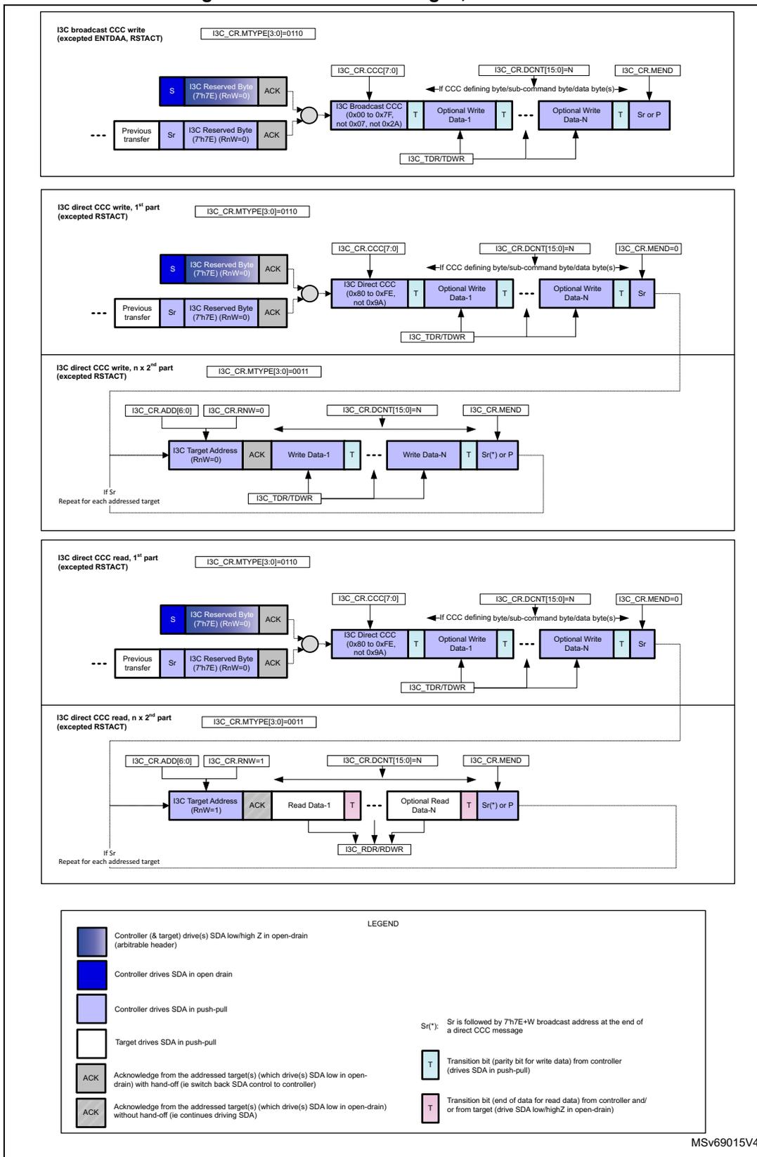
I3C broadcast CCC write (excepted ENTDA, RSTACT)
I3C_CR.MTYPE[3:0]=0110
Sequence: Previous transfer → Sr → I3C Reserved Byte (7h/E) (RnW=0) → ACK → I3C Broadcast CCC (0x00 to 0x7F, not 0x07, not 0x2A) → T → Optional Write Data-1 → T → ... → Optional Write Data-N → T → Sr or P
Control signals: I3C_CR.CCC[7:0], I3C_CR.DCNT[15:0]=N, I3C_CR.MEND, I3C_TDR/TDWR
I3C direct CCC write, 1
st
part (excepted RSTACT)
I3C_CR.MTYPE[3:0]=0110
Sequence: Previous transfer → Sr → I3C Reserved Byte (7h/E) (RnW=0) → ACK → I3C Direct CCC (0x80 to 0xFE, not 0x9A) → T → Optional Write Data-1 → T → ... → Optional Write Data-N → T → Sr
Control signals: I3C_CR.CCC[7:0], I3C_CR.DCNT[15:0]=N, I3C_CR.MEND=0, I3C_TDR/TDWR
I3C direct CCC write, n x 2
nd
part (excepted RSTACT)
I3C_CR.MTYPE[3:0]=0011
Sequence: I3C Target Address (RnW=0) → ACK → Write Data-1 → T → ... → Write Data-N → T → Sr(*) or P
Control signals: I3C_CR.ADD[6:0], I3C_CR.RNW=0, I3C_CR.DCNT[15:0]=N, I3C_CR.MEND, I3C_TDR/TDWR
Note: Repeat for each addressed target if Sr
I3C direct CCC read, 1
st
part (excepted RSTACT)
I3C_CR.MTYPE[3:0]=0110
Sequence: Previous transfer → Sr → I3C Reserved Byte (7h/E) (RnW=0) → ACK → I3C Direct CCC (0x80 to 0xFE, not 0x9A) → T → Optional Write Data-1 → T → ... → Optional Write Data-N → T → Sr
Control signals: I3C_CR.CCC[7:0], I3C_CR.DCNT[15:0]=N, I3C_CR.MEND=0, I3C_TDR/TDWR
I3C direct CCC read, n x 2
nd
part (excepted RSTACT)
I3C_CR.MTYPE[3:0]=0011
Sequence: I3C Target Address (RnW=1) → ACK → Read Data-1 → T → ... → Optional Read Data-N → T → Sr(*) or P
Control signals: I3C_CR.ADD[6:0], I3C_CR.RNW=1, I3C_CR.DCNT[15:0]=N, I3C_CR.MEND, I3C_RDR/RDWR
Note: Repeat for each addressed target if Sr
LEGEND
- Controller (& target) drive(s) SDA low/high Z in open-drain (arbitrable header)
- Controller drives SDA in open drain
- Controller drives SDA in push-pull
- Target drives SDA in push-pull
- ACK: Acknowledge from the addressed target(s) (which drive(s) SDA low in open-drain) with hand-off (ie switch back SDA control to controller)
- ACK: Acknowledge from the addressed target(s) (which drive(s) SDA low in open-drain) without hand-off (ie continues driving SDA)
- T: Transition bit (parity bit for write data) from controller (drives SDA in push-pull)
- T: Transition bit (end of data for read data) from controller and/or from target (drive SDA low/highZ in open-drain)
- Sr(*): Sr is followed by 7h7E+W broadcast address at the end of a direct CCC message
MSV69015V4
49.9.3 I3C broadcast ENTDAA CCC transfer, as controller
Figure 664 illustrates I3C broadcast ENTDAA CCC, as communicated on the I3C bus, and as programmed when acting as controller.
Figure 664. I3C broadcast ENTDAA CCC, as controller
![Timing diagram for I3C broadcast ENTDAA CCC transfer. The sequence starts with a Previous transfer ending in ACK. The controller then generates a Start (Sr) condition, followed by an I3C reserved byte (7'h7E) with RnW=0, and an ACK. Next, the controller sends the I3C broadcast CCC (ENTDAA=0x07) with a transition bit (T=0). This is followed by a loop for each target to be assigned: the controller sends an I3C reserved byte (7'h7E) with RnW=1, an ACK, 8 bytes of read data (48-bit unique ID(*), BCR, DCR), an assign address to the winning target (7 bits), a parity bit (PAR), and an ACK/NACK. The controller then generates another Start (Sr) condition, followed by an I3C reserved byte (7'h7E) with RnW=1, a NACK, and a Stop (P) condition. Control signals shown include I3C_CR.CCC[7:0]=0x07, I3C_CR.DCNT[15:0]=0, I3C_RDR/RDWR, I3C_TDR/TDWR, I3C_EVR.FCF=1, and I3C_SR (MID[7:0], DIR=0, XDCNT[15:0]=# of assigned targets).](/RM0481-STM32H523-33-562-63-573/0dd926e824c4039a745aba4554bd751c_img.jpg)
ENTDAA (I3C broadcast CCC write) (when IP is acting as controller)
Legend:
- Controller (and target) drives SDA low/high Z in open-drain (arbitrable header)
- Controller drives SDA in open-drain
- Controller drives SDA in push-pull
- Target(s) drive SDA low/highZ in open-drain (and controller in open-drain highZ)
- ACK Acknowledge from the addressed target(s) (which drives SDA low in open-drain) with hand-off (i.e. switch back SDA control to controller)
- ACK Acknowledge from the addressed target(s) (which drives SDA low in open-drain) without hand-off (i.e. continues driving SDA low/highZ in open-drain)
- T Transition bit (parity bit for CCC) from controller (drives SDA in push-pull)
(*): 48-bit unique/provisioned ID is subject to arbitration. The target which wins arbitration continues to provide its BCR and DCR.
MSV69013V4
49.9.4 I3C broadcast/direct RSTACT CCC transfer, as controller
Figure 665 illustrates I3C broadcast (write), direct write and read RSTACT CCC, as communicated on the I3C bus, and as programmed when acting as controller.
Figure 665. I3C broadcast, direct read and direct write RSTART CCC, as controller
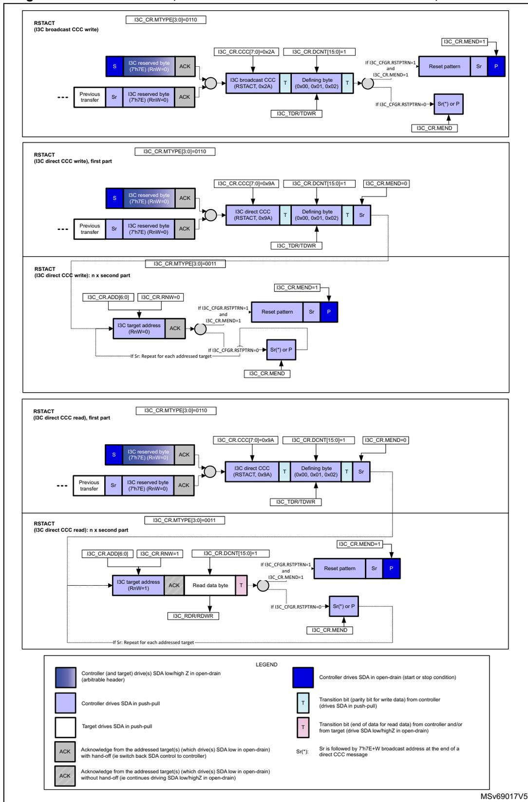
The figure illustrates five timing diagrams for I3C RSTART conditions, categorized by the I3C_CR.MTYPE[3:0] register value.
- RSTART (I3C broadcast CCC write): I3C_CR.MTYPE[3:0]=0110. The sequence starts with a previous transfer (Sr, I3C reserved byte (7h7E) (RnW=0), ACK). The controller drives the I3C broadcast CCC (RSTART, 0x2A) followed by a defining byte (0x00, 0x01, 0x02). The I3C_CR.CCC[7:0] register is set to 0x2A and I3C_CR.DCNT[15:0] is set to 1. The transfer ends with a reset pattern, Sr, and P if I3C_CR.MEND=1, or Sr(*) or P if I3C_CR.MEND=0.
- RSTART (I3C direct CCC write), first part: I3C_CR.MTYPE[3:0]=0110. The sequence starts with a previous transfer (Sr, I3C reserved byte (7h7E) (RnW=0), ACK). The controller drives the I3C direct CCC (RSTART, 0x9A) followed by a defining byte (0x00, 0x01, 0x02). The I3C_CR.CCC[7:0] register is set to 0x9A and I3C_CR.DCNT[15:0] is set to 1. The transfer ends with Sr and I3C_CR.MEND=0.
- RSTART (I3C direct CCC write): n x second part: I3C_CR.MTYPE[3:0]=0011. The sequence starts with the I3C target address (RnW=0) followed by ACK. The transfer ends with a reset pattern, Sr, and P if I3C_CR.MEND=1, or Sr(*) or P if I3C_CR.MEND=0. A note indicates that if Sr is repeated for each addressed target, the sequence continues.
- RSTART (I3C direct CCC read), first part: I3C_CR.MTYPE[3:0]=0110. The sequence starts with a previous transfer (Sr, I3C reserved byte (7h7E) (RnW=0), ACK). The controller drives the I3C direct CCC (RSTART, 0x9A) followed by a defining byte (0x00, 0x01, 0x02). The I3C_CR.CCC[7:0] register is set to 0x9A and I3C_CR.DCNT[15:0] is set to 1. The transfer ends with Sr and I3C_CR.MEND=0.
- RSTART (I3C direct CCC read): n x second part: I3C_CR.MTYPE[3:0]=0011. The sequence starts with the I3C target address (RnW=1) followed by ACK. The controller then drives the read data byte. The transfer ends with a reset pattern, Sr, and P if I3C_CR.MEND=1, or Sr(*) or P if I3C_CR.MEND=0. A note indicates that if Sr is repeated for each addressed target, the sequence continues.
LEGEND
- Controller (and target) drive(s) SDA low/high Z in open-drain (arbitrable header)
- Controller drives SDA in push-pull
- Target drives SDA in push-pull
- ACK Acknowledge from the addressed target(s) (which drive(s) SDA low in open-drain) with hand-off (ie switch back SDA control to controller)
- ACK Acknowledge from the addressed target(s) (which drive(s) SDA low in open-drain) without hand-off (ie continues driving SDA low/highZ in open-drain)
- Controller drives SDA in open-drain (start or stop condition)
- T Transition bit (parity bit for write data) from controller (drives SDA in push-pull)
- T Transition bit (end of data for read data) from controller and/or from target (drive SDA low/highZ in open-drain)
- Sr(*) or P Sr is followed by 7h7E+W broadcast address at the end of a direct CCC message
MSV69017V5
49.9.5 I3C broadcast/direct CCC transfer
(except ENTDA, DEFTGTS, DEFGRPA), as target
Figure 666 illustrates I3C broadcast CCC write transfer (except ENTDA, DEFTGTS, DEFGRPA), direct CCC read/write transfer, as communicated on the I3C bus, and as programmed when acting as target.
Figure 666. I3C CCC messages, as target
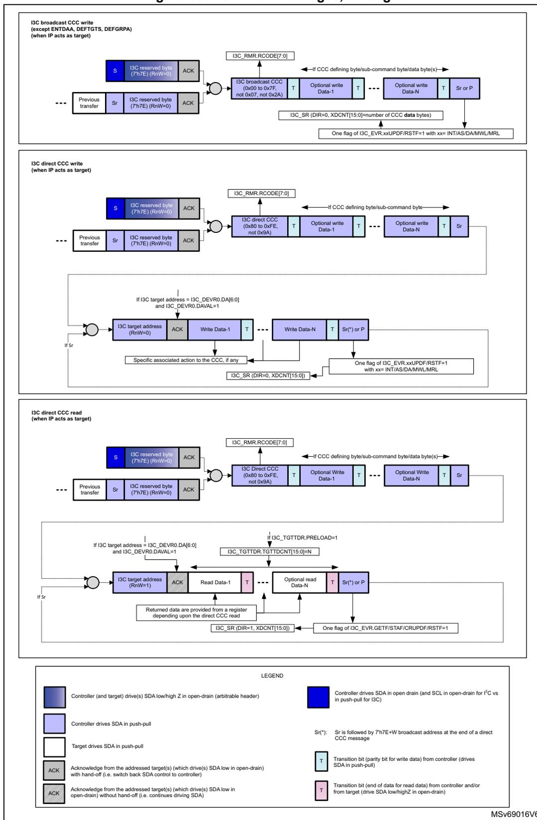
The diagram illustrates three types of I3C CCC messages when the IP acts as a target:
- I3C broadcast CCC write (except ENTDA, DEFTGTS, DEFGRPA) (when IP acts as target): This sequence starts with a previous transfer ending in a Stop (Sr) and an I3C reserved byte (7h7E) (RnW=0) followed by an ACK. The target then drives an I3C broadcast CCC (0x00 to 0x7F, not 0x07, not 0x2A) followed by optional write data (Data-1 to Data-N). Each data byte is followed by a Transition bit (T). The sequence ends with a Stop (Sr) or a P (Pre-emption). Control signals include I3C_RMR.CODE[7:0], I3C_SR (DIR=0, XDCNT[15:0]=number of CCC data bytes), and a flag in I3C_EVR.xxUPDF/RSTF=1 with xx= INT/AS/DA/MWL/MRL.
- I3C direct CCC write (when IP acts as target): This sequence starts with a previous transfer ending in a Stop (Sr) and an I3C reserved byte (7h7E) (RnW=0) followed by an ACK. The target then drives an I3C direct CCC (0x80 to 0xFE, not 0x9A) followed by optional write data (Data-1 to Data-N). Each data byte is followed by a Transition bit (T). The sequence ends with a Stop (Sr) or a P. Control signals include I3C_RMR.CODE[7:0], I3C_SR (DIR=0, XDCNT[15:0]), and a flag in I3C_EVR.xxUPDF/RSTF=1 with xx= INT/AS/DA/MWL/MRL. If the I3C target address equals I3C_DEVR0.DA[6:0] and I3C_DEVR0.DAVAL=1, the target address (RnW=0) is followed by an ACK and then write data (Data-1 to Data-N).
- I3C direct CCC read (when IP acts as target): This sequence starts with a previous transfer ending in a Stop (Sr) and an I3C reserved byte (7h7E) (RnW=0) followed by an ACK. The target then drives an I3C direct CCC (0x80 to 0xFE, not 0x9A) followed by optional write data (Data-1 to Data-N). Each data byte is followed by a Transition bit (T). The sequence ends with a Stop (Sr) or a P. Control signals include I3C_RMR.CODE[7:0], I3C_TGTTDR.PRELOAD=1, I3C_TGTTDR.TGTTDCNT[15:0]=N, I3C_SR (DIR=1, XDCNT[15:0]), and a flag in I3C_EVR.GETF/STAF/CRUPDF/RSTF=1. If the I3C target address equals I3C_DEVR0.DA[6:0] and I3C_DEVR0.DAVAL=1, the target address (RnW=1) is followed by an ACK and then read data (Data-1 to Data-N). Returned data are provided from a register depending upon the direct CCC read.
LEGEND
- Controller (and target) drive(s) SDA low/high Z in open-drain (arbitrable header)
- Controller drives SDA in push-pull
- Target drives SDA in push-pull
- ACK Acknowledge from the addressed target(s) (which drive(s) SDA low in open-drain) with hand-off (i.e. switch back SDA control to controller)
- ACK Acknowledge from the addressed target(s) (which drive(s) SDA low in open-drain) without hand-off (i.e. continues driving SDA)
- Sr('): Sr is followed by 7h7E+W broadcast address at the end of a direct CCC message
- T Transition bit (parity bit for write data) from controller (drives SDA in push-pull)
- T Transition bit (end of data for read data) from controller and/or from target (drive SDA low/highZ in open-drain)
MSV69016V6
49.9.6 I3C broadcast ENTDAA CCC transfer, as target
Figure 667 illustrates I3C broadcast ENTDAA CCC, as communicated on the I3C bus, and as programmed when acting as target.
Figure 667. I3C broadcast ENTDAA CCC, as target
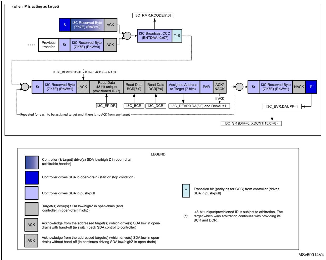
(when IP is acting as target)
The diagram illustrates the I3C broadcast ENTDAA CCC transfer sequence when the IP is acting as a target. The sequence starts with a previous transfer followed by a start condition (Sr) and an I3C Reserved Byte (7'h7E) with RnW=0, which is acknowledged (ACK). The controller then drives the I3C Broadcast CCC (ENTDAA=0x07) with a transition bit (T=0). This is followed by a read data sequence: Sr, I3C Reserved Byte (7'h7E) with RnW=1, ACK, Read Data 48-bit unique provisioned ID (*), Read Data BCR[7:0], Read Data DCR[7:0], Assigned Address to Target (7 bits), PAR, and ACK/NACK. The target responds with ACK if I3C_DEVR0.DAVAL = 0, otherwise NACK. The sequence repeats for each target until no ACK is received from any target. Upon receiving a NACK, the controller drives a stop condition (P). The target then sets I3C_EVR.DAUPF=1 and I3C_SR(DIR=0, XDCNT[15:0]=8). The I3C_RMR.RCODE[7:0] is also updated.
LEGEND
- Controller (& target) drive(s) SDA low/high Z in open-drain (arbitrable header)
- Controller drives SDA in open-drain (start or stop condition)
- Controller drives SDA in push-pull
- Target(s) drive(s) SDA low/highZ in open-drain (and controller in open-drain highZ)
- ACK Acknowledge from the addressed target(s) (which drive(s) SDA low in open-drain) with hand-off (ie switch back SDA control to controller)
- ACK Acknowledge from the addressed target(s) (which drive(s) SDA low in open-drain) without hand-off (ie continues driving SDA low/highZ in open-drain)
- T Transition bit (parity bit for CCC) from controller (drives SDA in push-pull)
- (*): 48-bit unique/provisioned ID is subject to arbitration. The target which wins arbitration continues with providing its BCR and DCR.
MSV69014V4
49.9.7 I3C broadcast DEFTGTS CCC transfer, as target
Figure 668 illustrates I3C broadcast DEFTGTS CCC, as communicated on the I3C bus, and as programmed when acting as target.
Figure 668. I3C broadcast DEFTGTS CCC, as target
![Timing diagram for I3C broadcast DEFTGTS CCC transfer. The diagram shows the sequence of events on the I3C bus between an Active Controller and multiple Target or Group units. The sequence starts with a Start (S) or Repeated Start (Sr), followed by the I3C Reserved Byte (7'h7E) (RnW=0), and an ACK. Then the I3C Broadcast CCC (DEFTGTS=0x08) is sent with a parity bit T=0, followed by Count[7:0] and a transition bit T. This is followed by a sequence for the Active Controller: {DynAddr[7:1], 1'b0}, T, DCR[7:0], T, BCR[7:0], T, and StaticAddr (7'h7E), T. Then for each Target or Group: {DynAddr[7:1], 1'b0}, T, DCR[7:0], T, BCR[7:0], T, {StaticAddr[7:1], 1'b0}, T. The sequence ends with a Repeated Start (Sr) or Stop (P). Register interactions like I3C_RMR.RCODE[7:0], I3C_RDR/RDWR, I3C_SR (DIR=0, XDCNT[15:0]=1+ 4x Count), and I3C_EVR.DEFF=1 are shown.](/RM0481-STM32H523-33-562-63-573/227c29905779ea7f9e244fd963a460c5_img.jpg)
DEFTGTS
(I3C broadcast CCC write)
(when IP is acting as target)
LEGEND
- Controller (& target) drive(s) SDA low/high Z in open-drain (arbitrable header)
- Controller drives SDA in open-drain
- Controller drives SDA in push-pull
- ACK Acknowledge from the addressed target(s) (which drive(s) SDA low in open-drain) with hand-off (ie switch back SDA control to controller)
- T Transition bit (parity bit for CCC) from controller (drives SDA in push-pull)
MSV69012V3
49.9.8 I3C broadcast DEFGRPA CCC transfer, as target
Figure 669 illustrates I3C broadcast DEFGRPA CCC, as communicated on the I3C bus, and as programmed when acting as target.
Figure 669. I3C broadcast DEFGRPA CCC, as target
![Timing diagram for I3C broadcast DEFGRPA CCC transfer. The diagram shows a sequence of messages on the I3C bus. It starts with a 'Previous transfer' followed by a 'Sr' (Start) and an 'I3C Reserved Byte (7'h7E) (RnW=0)' with an 'ACK'. The main part is the 'I3C Broadcast CCC (DEFGRPA=0x2B)' which includes fields for 'T=0', 'Group Addr. 1'b0', 'T', 'Group Descriptor', 'T', 'Count', 'T', 'Dyn Addr#1, 1'b0', 'T', 'DynAddr#n, 1'b0', 'T', and 'Sr or P'. Above the 'I3C Broadcast CCC' field is a register 'I3C_RMR.RCODE[7:0]'. Below the 'Group Descriptor' field is a register 'I3C_RDR/RDWR'. Below the 'DynAddr#n, 1'b0' field are registers 'I3C_SR (DIR=0,XDCNT[15:0])' and 'I3C_EVR.GRPF=1'. A legend at the bottom explains the SDA signal states: dark blue for open-drain (arbitrable header), medium blue for open-drain, light blue for push-pull, and grey for ACK from target(s).](/RM0481-STM32H523-33-562-63-573/c42119e25068c68e19d2746037c4b5e4_img.jpg)
DEFGRPA (I3C broadcast CCC write) (when IP is acting as target)
LEGEND
- Controller (& target) drive(s) SDA low/high Z in open-drain (arbitrable header)
- Controller drives SDA in open-drain
- Controller drives SDA in push-pull
- ACK Acknowledge from the addressed target(s) (which drive(s) SDA low in open-drain) with hand-off (ie switch back SDA control to controller)
- T Transition bit (parity bit for CCC) from controller (drives SDA in push-pull)
MSV69010V3
49.9.9 I3C direct GETSTATUS CCC response, as target
When the I3C acts as target, the hardware returns two data bytes on reception of GETSTATUS CCC, with format 1 (without defining byte or with defining byte TGTSTAT = 0x00), or format 2 (with defining byte PRECR = 0x91).
The returned 2-byte STATUS[15:0] with format 1 on the I3C bus is then as follows:
- • STATUS[15:14] = 00 (unused)
- • STATUS[13] = 1 if a missed start was detected since the former GETSTATUS CCC, else 0
- • STATUS[12] = 1 if an overrun/underrun error was detected since the former GETSTATUS CCC, else 0
- • STATUS[11] = 1 if an SCL stable for more than 125 µs was detected during an SDR read since the former GETSTATUS CCC, else 0
- • STATUS[10:8] = 000 to 110: encoded value x = 0 to 6, corresponding to a target error TEx if a protocol error was detected since the former GETSTATUS CCC (if STATUS[5] = 1), else 000
- • STATUS[7:6] = 00 (ready to prepare for hand-off procedure)
- • STATUS[5] = 1 if a protocol error was detected since the former GETSTATUS CCC, else 0
- • STATUS[4] = 0 (reserved)
- • STATUS[3:1] = 000 (unused)
- • STATUS[0] = 1 if there is a pending interrupt (if an IBI is configured in the I3C_CR register, and IBIEN = 1 and DAVAL = 1 in the I3C_DEVR0 register, and the IBI is not yet acknowledged by the controller neither disabled via DISEC), else 0
The returned 2-byte STATUS[15:0] with format 2 on the I3C bus is then as follows:
- • STATUS[15:8] = 0000 0000 (unused)
- • STATUS[7:2] = 000000 (unused)
- • STATUS[1] = 1 if a received DEFTGTS or a received DEFGRPA CCC is still under software processing, and the related event is not yet cleared by software (DEFF = 1 or GRPF = 1 in the I3C_EVR register); the controller must wait before issuing a GETACCR CCC (else it is not acknowledged)
- • STATUS[0] = 1 if a DEFTGTS or DEFGRPA CCC may have been missed. This bit is asserted if a missed start is detected (WKPF = 1 in the I3C_EVR register), de-asserted if DEFF = 1 or GRPF = 1 in the I3C_EVR register.
Completion of a GETSTATUS CCC of format 1 is reported by STAF = 1 in the I3C_EVR register, and the corresponding interrupt if enabled (if STAIE = 1 in the I3C_IER register).
Completion of a GETSTATUS CCC of format 2 is reported by GETF = 1 in the I3C_EVR register, and the corresponding interrupt if enabled (if GETIE = 1 in the I3C_IER register).
49.9.10 I3C private read/write transfer, as controller
Figure 670 illustrates private read/write transfer, as communicated on the I3C bus, and as programmed when acting as controller.
Figure 670. I3C private read/write messages, as controller
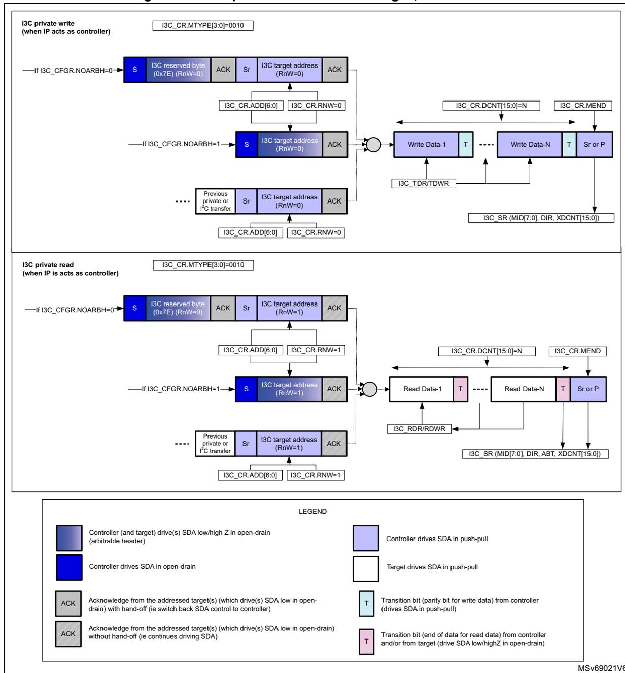
I3C private write (when IP acts as controller)
Condition:
I3C_CR_MTYPE[3:0]=0010
Sequence 1 (if
I3C_CFGR.NOARBH=0
): S (Controller drives SDA in open-drain) → I3C reserved byte (0x7E) (RnW=0) (Controller drives SDA in open-drain) → ACK (Acknowledge from the addressed target(s) which drive(s) SDA low in open-drain) with hand-off → Sr (Controller drives SDA in open-drain) → I3C target address (RnW=0) (Controller drives SDA in open-drain) → ACK (Acknowledge from the addressed target(s) which drive(s) SDA low in open-drain) without hand-off.
Sequence 2 (if
I3C_CFGR.NOARBH=1
): S (Controller drives SDA in open-drain) → I3C target address (RnW=0) (Controller drives SDA in open-drain) → ACK (Acknowledge from the addressed target(s) which drive(s) SDA low in open-drain) without hand-off.
Previous private or I2C transfer: Sr (Controller drives SDA in open-drain) → I3C target address (RnW=0) (Controller drives SDA in open-drain) → ACK (Acknowledge from the addressed target(s) which drive(s) SDA low in open-drain) without hand-off.
Data transfer: Write Data-1 (T) → ... → Write Data-N (T) → Sr or P. Control signals:
I3C_CR_DCNT[15:0]=N
,
I3C_CR_MEND
,
I3C_TDR/TDWR
,
I3C_SR (MID[7:0], DIR, XDCNT[15:0])
.
I3C private read (when IP acts as controller)
Condition:
I3C_CR_MTYPE[3:0]=0010
Sequence 1 (if
I3C_CFGR.NOARBH=0
): S (Controller drives SDA in open-drain) → I3C reserved byte (0x7E) (RnW=0) (Controller drives SDA in open-drain) → ACK (Acknowledge from the addressed target(s) which drive(s) SDA low in open-drain) with hand-off → Sr (Controller drives SDA in open-drain) → I3C target address (RnW=1) (Controller drives SDA in open-drain) → ACK (Acknowledge from the addressed target(s) which drive(s) SDA low in open-drain) without hand-off.
Sequence 2 (if
I3C_CFGR.NOARBH=1
): S (Controller drives SDA in open-drain) → I3C target address (RnW=1) (Controller drives SDA in open-drain) → ACK (Acknowledge from the addressed target(s) which drive(s) SDA low in open-drain) without hand-off.
Previous private or I2C transfer: Sr (Controller drives SDA in open-drain) → I3C target address (RnW=1) (Controller drives SDA in open-drain) → ACK (Acknowledge from the addressed target(s) which drive(s) SDA low in open-drain) without hand-off.
Data transfer: Read Data-1 (T) → ... → Read Data-N (T) → Sr or P. Control signals:
I3C_CR_DCNT[15:0]=N
,
I3C_CR_MEND
,
I3C_RDR/RDWR
,
I3C_SR (MID[7:0], DIR, ABT, XDCNT[15:0])
.
LEGEND
- Controller (and target) drive(s) SDA low/high Z in open-drain (arbitrable header)
- Controller drives SDA in open-drain
- Controller drives SDA in push-pull
- Target drives SDA in push-pull
- ACK: Acknowledge from the addressed target(s) which drive(s) SDA low in open-drain) with hand-off (ie switch back SDA control to controller)
- ACK: Acknowledge from the addressed target(s) which drive(s) SDA low in open-drain) without hand-off (ie continues driving SDA)
- T: Transition bit (parity bit for write data) from controller (drives SDA in push-pull)
- T: Transition bit (end of data for read data) from controller and/or from target (drive SDA low/highZ in open-drain)
MSv69021V6
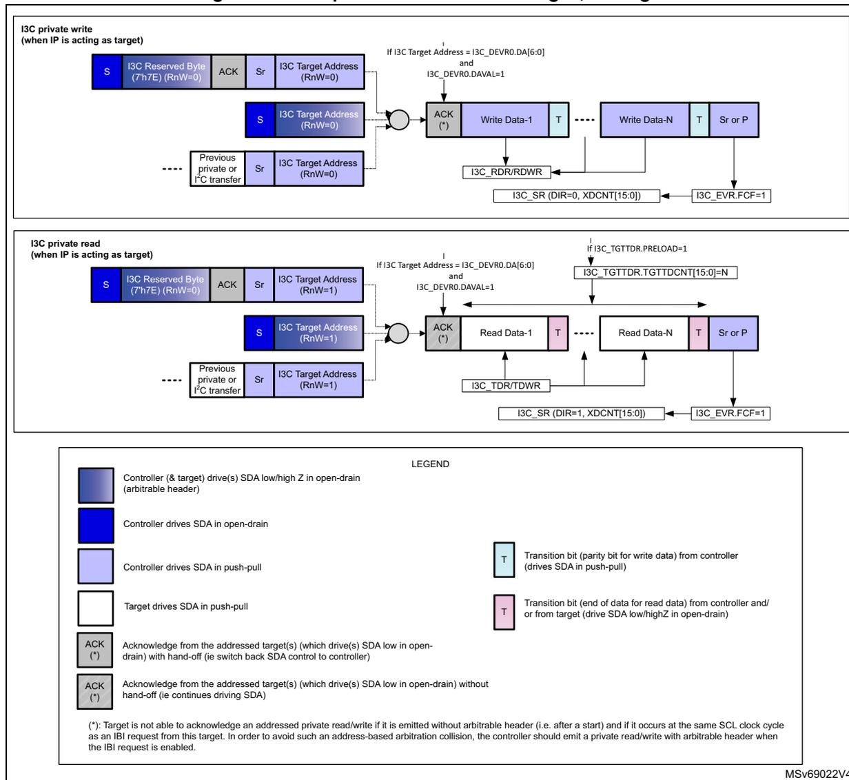
49.9.11 I3C private read/write transfer, as target
Figure 671 illustrates I3C private read/write transfer, as communicated on the I3C bus, and as programmed when acting as target.
Figure 671. I3C private read/write messages, as target
I3C private write (when IP is acting as target)
The diagram shows the sequence of messages on the I3C bus for a private write transfer. It starts with an arbitrary header (S, I3C Reserved Byte (7'h7E) (RnW=0), ACK, Sr, I3C Target Address (RnW=0)). This is followed by a start (S) and I3C Target Address (RnW=0). The target then sends an ACK (*). The controller then sends Write Data-1, Write Data-N, and finally a Stop or Repeated Start (Sr or P). The target receives the data via I3C_RDR/RDWR. The I3C_SR (DIR=0, XDCNT[15:0]) and I3C_EVR.FCF=1 flags are set. The transfer is enabled if I3C Target Address = I3C_DEVVR0.DA[6:0] and I3C_DEVVR0.DAVAL=1.
I3C private read (when IP is acting as target)
The diagram shows the sequence of messages on the I3C bus for a private read transfer. It starts with an arbitrary header (S, I3C Reserved Byte (7'h7E) (RnW=0), ACK, Sr, I3C Target Address (RnW=1)). This is followed by a start (S) and I3C Target Address (RnW=1). The target then sends an ACK (*). The controller then receives Read Data-1, Read Data-N, and finally a Stop or Repeated Start (Sr or P). The target sends the data via I3C_TDR/TDWR. The I3C_SR (DIR=1, XDCNT[15:0]) and I3C_EVR.FCF=1 flags are set. The transfer is enabled if I3C Target Address = I3C_DEVVR0.DA[6:0] and I3C_DEVVR0.DAVAL=1. Additionally, if I3C_TGTTDR.PRELOAD=1, then I3C_TGTTDR.TGTTDCNT[15:0]=N.
LEGEND
- Controller (& target) drive(s) SDA low/high Z in open-drain (arbitrable header)
- Controller drives SDA in open-drain
- Controller drives SDA in push-pull
- Target drives SDA in push-pull
- ACK (*) Acknowledge from the addressed target(s) (which drive(s) SDA low in open-drain) with hand-off (ie switch back SDA control to controller)
- ACK (*) Acknowledge from the addressed target(s) (which drive(s) SDA low in open-drain) without hand-off (ie continues driving SDA)
- T Transition bit (parity bit for write data) from controller (drives SDA in push-pull)
- T Transition bit (end of data for read data) from controller and/or from target (drive SDA low/highZ in open-drain)
(*): Target is not able to acknowledge an addressed private read/write if it is emitted without arbitrable header (i.e. after a start) and if it occurs at the same SCL clock cycle as an IBI request from this target. In order to avoid such an address-based arbitration collision, the controller should emit a private read/write with arbitrable header when the IBI request is enabled.
MSV69022V4
49.9.12 Legacy I 2 C read/write transfer, as controllerFigure 672 illustrates legacy I 2 C read/write transfer, as communicated on the I3C bus, and as programmed when acting as controller.
Figure 672. Legacy I 2 C read/write messages, as controller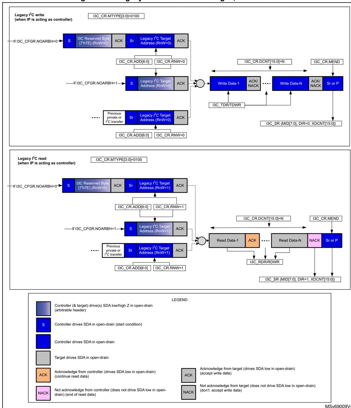
Legacy I 2 C write (when IP is acting as controller) I3C_CR.MTYPE[3:0]=0100
—If I3C_CFGR.NOARBH=0→
S | I3C Reserved Byte (7'h7E) (RnW=0) | ACK | Sr | Legacy I 2 C Target Address (RnW=0) | ACK
↑
I3C_CR.ADD[6:0] | I3C_CR.RNW=0
—If I3C_CFGR.NOARBH=1→
S | Legacy I 2 C Target Address (RnW=0) | ACK
↑
I3C_CR.ADD[6:0] | I3C_CR.RNW=0
Previous private or I 2 C transfer → Sr | Legacy I 2 C Target Address (RnW=0) | ACK
↑
I3C_CR.ADD[6:0] | I3C_CR.RNW=0
→ Write Data-1 | ACK/NACK | ... | Write Data-N | ACK/NACK | Sr or P
↑
I3C_TDR/TDWR
← I3C_CR.DCNT[15:0]=N
↓ I3C_CR.MEND
I3C_SR (MID[7:0], DIR=0, XDCNT[15:0])
Legacy I 2 C read (when IP is acting as controller) I3C_CR.MTYPE[3:0]=0100
—If I3C_CFGR.NOARBH=0→
S | I3C Reserved Byte (7'h7E) (RnW=0) | ACK | Sr | Legacy I 2 C Target Address (RnW=1) | ACK
↑
I3C_CR.ADD[6:0] | I3C_CR.RNW=1
—If I3C_CFGR.NOARBH=1→
S | Legacy I 2 C Target Address (RnW=1) | ACK
↑
I3C_CR.ADD[6:0] | I3C_CR.RNW=1
Previous private or I 2 C transfer → Sr | Legacy I 2 C Target Address (RnW=1) | ACK
↑
I3C_CR.ADD[6:0] | I3C_CR.RNW=1
→ Read Data-1 | ACK | ... | Read Data-N | NACK | Sr or P
↑
I3C_RDR/RDWR
← I3C_CR.DCNT[15:0]=N
↓ I3C_CR.MEND
I3C_SR (MID[7:0], DIR=1, XDCNT[15:0])
LEGEND
| Controller (& target) drive(s) SDA low/high Z in open-drain (arbitrable header) | |
| S Controller drives SDA in open-drain (start condition) | |
| Controller drives SDA in open-drain | |
| Target drives SDA in open-drain | |
| ACK Acknowledge from controller (drives SDA low in open-drain) (continue read data) | ACK Acknowledge from target (drives SDA low in open-drain) (accept write data) |
| NACK Not acknowledge from controller (does not drive SDA low in open-drain) (end of read data) | NACK Not acknowledge from target (does not drive SDA low in open-drain) (don't accept write data) |
MSv69009V4
49.9.13 I3C IBI transfer, as controller/target
Figure 673 illustrates IBI (in-band interrupt) transfer, as communicated on the I3C bus, and as programmed when acting as target or received as controller.
Figure 673. IBI transfer, as controller/target
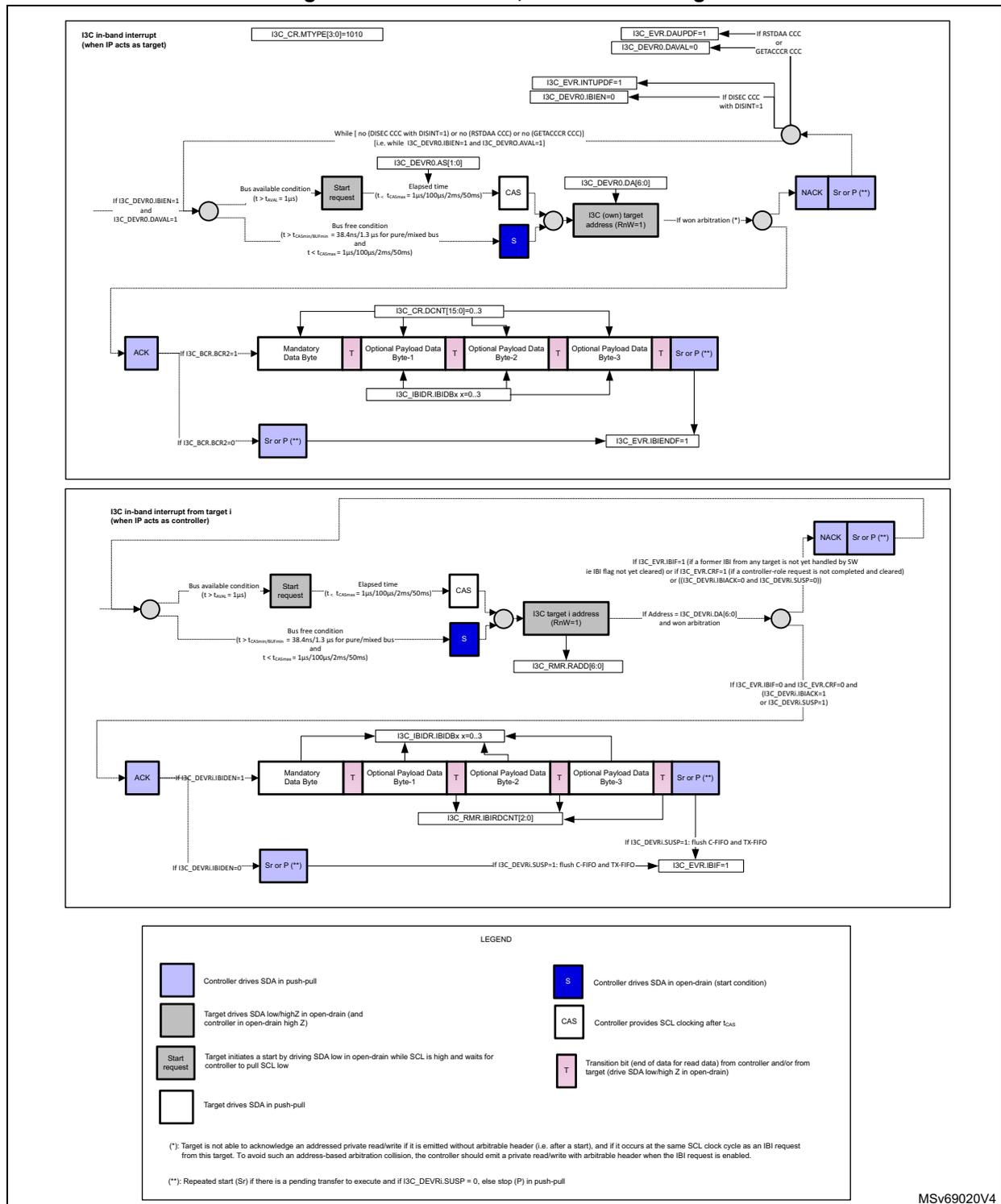
I3C in-band interrupt (when IP acts as target)
- I3C_CR.MTYPE[3:0]=1010
- I3C_EVR.DAUPDF=1 (If RSTDAA CCC or GETACCCR CCC)
- I3C_EVR.INTUPDF=1, I3C_DEVR0.IBIEN=0 (If DISEC CCC with DISINT=1)
- While [no (DISEC CCC with DISINT=1) or no (RSTDAA CCC) or no (GETACCCR CCC)] [i.e. while I3C_DEVR0.IBIEN=1 and I3C_DEVR0.AVAIL=1]
- Bus available condition ( \( t > t_{bus} = 1\mu s \) ) and I3C_DEVR0.IBIEN=1 and I3C_DEVR0.AVAIL=1 → Start request
- Elapsed time ( \( t - t_{CASmin} = 1\mu s/100\mu s/2ms/50ms \) ) → CAS
- Bus free condition ( \( t > t_{CASmin/BUSmin} = 38.4ns/1.3\mu s \) for pure/mixed bus and \( t < t_{CASmax} = 1\mu s/100\mu s/2ms/50ms \) ) → S
- I3C_DEVR0.AS[1:0] → I3C_DEVR0.DA[6:0] → I3C (own) target address (RnW=1)
- If won arbitration (*): ACK (if I3C_BCR.BCR2=1) → Mandatory Data Byte → T → Optional Payload Data Byte-1 → T → Optional Payload Data Byte-2 → T → Optional Payload Data Byte-3 → T → Sr or P (**)
- If I3C_BCR.BCR2=0 → Sr or P (**)
- I3C_EVR.IBIENDF=1
I3C in-band interrupt from target i (when IP acts as controller)
- Bus available condition ( \( t > t_{bus} = 1\mu s \) ) → Start request
- Elapsed time ( \( t - t_{CASmin} = 1\mu s/100\mu s/2ms/50ms \) ) → CAS
- Bus free condition ( \( t > t_{CASmin/BUSmin} = 38.4ns/1.3\mu s \) for pure/mixed bus and \( t < t_{CASmax} = 1\mu s/100\mu s/2ms/50ms \) ) → S
- I3C target i address (RnW=1) → I3C_RMR.RADD[6:0]
- If address = I3C_DEVRi.DA[6:0] and won arbitration:
- If I3C_EVR.IBIF=1 (if a former IBI from any target is not yet handled by SW ie IBI flag not yet cleared) or if I3C_EVR.CRF=1 (if a controller-role request is not completed and cleared) or ((I3C_DEVRi.IBIBACK=0 and I3C_DEVRi.SUSP=0)) → NACK → Sr or P (**)
- If I3C_EVR.IBIF=0 and I3C_EVR.CRF=0 and (I3C_DEVRi.IBIBACK=1 or I3C_DEVRi.SUSP=1) → ACK (if I3C_DEVRi.IBIDEN=1) → Mandatory Data Byte → T → Optional Payload Data Byte-1 → T → Optional Payload Data Byte-2 → T → Optional Payload Data Byte-3 → T → Sr or P (**)
- If I3C_DEVRi.IBIDEN=0 → Sr or P (**)
- If I3C_DEVRi.SUSP=1: flush C-FIFO and TX-FIFO → I3C_EVR.IBIF=1
LEGEND
- Controller drives SDA in push-pull
- Target drives SDA low/highZ in open-drain (and controller in open-drain high Z)
- Start request Target initiates a start by driving SDA low in open-drain while SCL is high and waits for controller to pull SCL low
- Target drives SDA in push-pull
- S Controller drives SDA in open-drain (start condition)
- CAS Controller provides SCL clocking after \( t_{CAS} \)
- T Transition bit (end of data for read data) from controller and/or from target (drive SDA low/high Z in open-drain)
(*) Target is not able to acknowledge an addressed private read/write if it is emitted without arbitrable header (i.e. after a start), and if it occurs at the same SCL clock cycle as an IBI request from this target. To avoid such an address-based arbitration collision, the controller should emit a private read/write with arbitrable header when the IBI request is enabled.
(**) Repeated start (Sr) if there is a pending transfer to execute and if I3C_DEVRi.SUSP = 0, else stop (P) in push-pull
MSv69020V4
When the I3C peripheral acts as controller, the I3C_IBIDR register is used to receive the IBI data payload. Consequently, the IBI request from the target must not exceed a 4-byte data payload. If there is more information to be exchanged in the context of this in-band interrupt, the controller software must issue a private read.
49.9.14 I3C hot-join request transfer, as controller/target
Figure 674 illustrates hot-join request transfer, as communicated on the I3C bus, and as programmed when acting as target or received as controller.
Figure 674. Hot-join request transfer, as controller/target
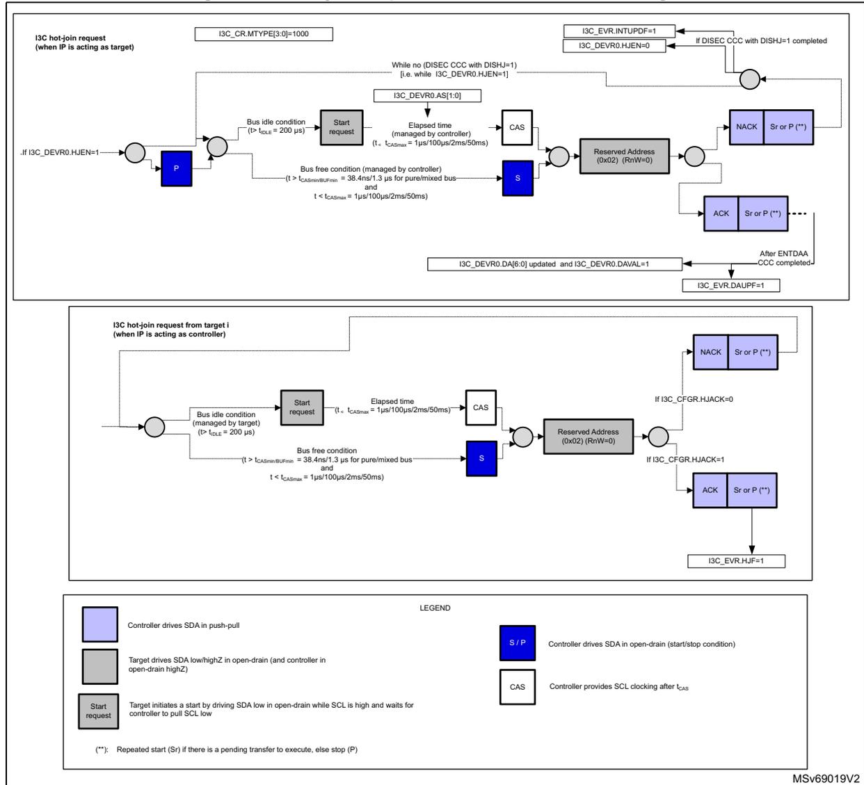
I3C hot-join request (when IP is acting as target)
Registers: I3C_CR.MTYPE[3:0]=1000, I3C_EVR.INTUPDF=1, I3C_DEVR0.HJEN=0
Condition: While no (DISEC CCC with DISHU=1) [i.e. while I3C_DEVR0.HJEN=1]
Sequence: Start request → CAS → S → Reserved Address (0x02) (RnW=0) → NACK / Sr or P (**) → ACK / Sr or P (**) → After ENTDA CCC completed- → I3C_EVR.DAUPF=1
Timing: Bus idle condition (> t idle = 200 µs), Bus free condition (managed by controller) (> t idle = 200 µs), Elapsed time (managed by controller) (t idle < t CASmax = 1µs/100µs/2ms/50ms)
I3C hot-join request from target i (when IP is acting as controller)
Sequence: Start request → CAS → S → Reserved Address (0x02) (RnW=0) → NACK / Sr or P (**) → ACK / Sr or P (**) → I3C_EVR.HJUF=1
Timing: Bus idle condition (managed by target) (> t idle = 200 µs), Bus free condition (managed by controller) (> t idle = 200 µs), Elapsed time (managed by controller) (t idle < t CASmax = 1µs/100µs/2ms/50ms)
LEGEND
- Controller drives SDA in push-pull
- Target drives SDA low/highZ in open-drain (and controller in open-drain highZ)
- Start request: Target initiates a start by driving SDA low in open-drain while SCL is high and waits for controller to pull SCL low
- S / P: Controller drives SDA in open-drain (start/stop condition)
- CAS: Controller provides SCL clocking after t CAS
(**): Repeated start (Sr) if there is a pending transfer to execute, else stop (P)
MSv69019V2
49.9.15 I3C controller-role request transfer, as controller/target
Figure 675 illustrates controller-role request transfer, as communicated on the I3C bus, and as programmed when acting as target or received as controller.
Figure 675. Controller-role request transfer, as controller/target
![Timing diagram for I3C controller-role request transfer. The diagram is split into two horizontal sections. The top section shows the sequence when the IP is acting as a target, starting with a request to set I3C_CR.MTYPE[3:0]=1001. It details the bus availability conditions, start request, elapsed time for CAS, and the subsequent address transfer (Own Target Address RnW=0). It also shows the arbitration logic leading to either a NACK or ACK/Sr or P. The bottom section shows the sequence when the IP is acting as a controller, starting with a request from target i. It details the bus availability, start request, elapsed time for CAS, and the subsequent address transfer (I3C Target i Address RnW=0). It also shows the arbitration logic leading to either a NACK or ACK/Sr or P. A legend at the bottom defines the symbols for SDA driving (push-pull, open-drain start, open-drain highZ), CAS, and the symbols for start request and arbitration outcomes.](/RM0481-STM32H523-33-562-63-573/2e07b1231183bfd9a2bfb5b3e76c53ca_img.jpg)
I3C controller-role request (when IP is acting as target)
I3C_CR.MTYPE[3:0]=1001
I3C_EVR.DAUPF=1
I3C_DEVR0.DAVAL=0 ← If RSTDAA CCC
I3C_EVR.INTUPDF=1 ← If DISEC CCC with DISCR=1
I3C_DEVR0.CREN=0
While [ no (DISEC CCC with DISCR=1) or no (RSTDAA CCC) ]
[ i.e. while I3C_DEVR0.CREN=1 and I3C_DEVR0.AVAL=1 ]
If I3C_DEVR0.CREN=1 and I3C_DEVR0.DAVAL=1 → Bus available condition ( \( t > t_{AWL} = 1\mu s \) ) → Start request → Elapsed time ( \( t < t_{CASmax} = 1\mu s/100\mu s/2ms/50ms \) ) → CAS → I3C_DEVR0.AS[1:0]
Bus free condition ( \( t > t_{CASminBUFin} = 38.4ns/1.3\mu s \) for pure/mixed bus and \( t < t_{CASmax} = 1\mu s/100\mu s/2ms/50ms \) ) → S → I3C_DEVR0.DA[6:0] → I3C (Own) Target Address (RnW=0)
→ If won arbitration (*) → ACK or Sr or P (**) → After GETACCCR CCC completed → I3C_EVR.CRUPDF=1
→ NACK or Sr or P (**)
I3C controller-role request from target i (when IP is acting as controller)
Bus available condition ( \( t > t_{AWL} = 1\mu s \) ) → Start request → Elapsed time ( \( t < t_{CASmax} = 1\mu s/100\mu s/2ms/50ms \) ) → CAS → I3C Target i Address (RnW=0) → I3C_RMR.RADD[6:0]
Bus free condition ( \( t > t_{CASminBUFin} = 38.4ns/1.3\mu s \) for pure/mixed bus and \( t < t_{CASmax} = 1\mu s/100\mu s/2ms/50ms \) ) → S
→ If won arbitration → If I3C_EVR.CRF=1 or I3C_EVR.IBIF=1 (if a former controller-role or IBI request is not yet handled by SW ie CRF and IBIF flags not yet cleared) or I3C_DEVR1.CRACK=0 → NACK or Sr or P (**)
→ If I3C_EVR.CRF=0 and I3C_EVR.IBIF=0 and I3C_DEVR1.CRACK=1 → ACK or Sr or P (**) → I3C_EVR.CRF=1
LEGEND
- Controller drives SDA in push-pull
- S Controller drives SDA in open-drain (start condition)
- Target drives SDA low/highZ in open-drain (and controller in open-drain highZ)
- CAS Controller provides SCL clocking after \( t_{CAS} \)
- Start request Target initiates a start by driving SDA low in open-drain while SCL is high and waits for controller to pull SCL low
- (*): Target is not able to acknowledge an addressed private read/write if it is emitted without arbitrable header (i.e. after a start) and if it occurs at the same SCL clock cycle as an IBI request from this target. In order to avoid such an address-based arbitration collision, the controller should emit a private read/write with arbitrable header when the IBI request is enabled.
- (**): Repeated start (Sr) if there is a pending transfer to execute, else stop (P)
MSV69018V2
49.10 I3C FIFOs management, as controller
49.10.1 C-FIFO management, as controller
When controller, as illustrated in figures of Section 49.9 , C-FIFO can be used during any of the following transfers:
- • broadcast CCC ( Figure 663 , Figure 664 , Figure 665 )
- • direct read/write CCC (
Figure 665
)
- – command part, first message
- – data part, next message(s)
- • private read/write ( Figure 670 )
- • legacy I2C read/write ( Figure 672 )
- • software-initiated error recovery (SCL forced to be stopped until next header message followed by HDR exit pattern)
Figure 676 illustrates the management of the C-FIFO for queuing control word(s) on the I3C bus, when the I3C peripheral acts as controller.
Figure 676. C-FIFO management, as controller
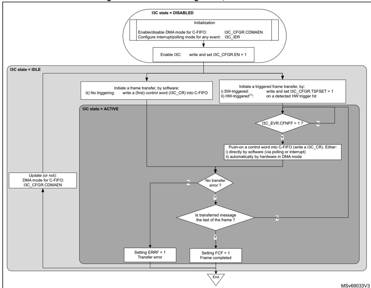
graph TD
    subgraph DISABLED [I3C state = DISABLED]
        Init[Initialization:
Enable/disable DMA mode for C-FIFO: I3C_CFGR.CDMAEN
Configure interrupt/polling mode for any event: I3C_IER]
        Enable[Enable I3C: write and set I3C_CFGR.EN = 1]
    end

    subgraph IDLE [I3C state = IDLE]
        InitSW[Initiate a frame transfer, by software:
iii) No triggering: write a (first) control word (I3C_CR) into C-FIFO]
        InitTrigger[Initiate a triggered frame transfer, by:
i) SW-triggered: write and set I3C_CFGR.TSFSET = 1
on a detected HW trigger hit
ii) HW-triggered1:]
    end

    subgraph ACTIVE [I3C state = ACTIVE]
        Decision1{I3C_EVR.CFNFF = 1 ?}
        Push[Push-on a control word into C-FIFO (write a I3C_CR). Either:
i) directly by software (via polling or interrupt)
ii) automatically by hardware in DMA mode]
        Decision2{No transfer error ?}
        Decision3{Is transferred message the last of the frame ?}
        Error[Setting ERRF = 1
Transfer error]
        Success[Setting FCF = 1
Frame completed]
    end

    UpdateDMA[Update (or not):
DMA mode for C-FIFO:
I3C_CFGR.CDMAEN]

    End[/End/]

    Init --> Enable
    Enable --> InitSW
    Enable --> InitTrigger
    InitSW --> Decision1
    InitTrigger --> Decision1
    Decision1 -- N --> Decision1
    Decision1 -- Y --> Push
    Push --> Decision2
    Decision2 -- N --> UpdateDMA
    Decision2 -- Y --> Decision3
    Decision3 -- N --> Push
    Decision3 -- Y --> Success
    Success --> End
    Error --> UpdateDMA
    UpdateDMA --> InitSW
MSV69033V3
- 1. This feature is implementation-dependent and can be unavailable. Refer to Section 49.3.4 .
First, the software must initialize the C-FIFO management via CDMAEN in the I3C_CFGR register, to be written either:
- • directly by the software (if CDMAEN = 0) at the control word level:
- – via polling mode (CFNFIE = 0 in the I3C_IER register): waiting for a next control word is requested by the hardware (CFNFF = 1 in the I3C_IER register) before an explicit write to the I3C_CR register
- – via enabled interrupt notification if CFNFIE = 1
- • by the allocated DMA channel (if CDMAEN = 1) to the corresponding DMA request from the I3C peripheral (i3c_tc_dma):
- – as configured at block level, the DMA is automatically pushing-on/writing control word(s) into the I3C_CR register from its memory source buffer, until the frame completion (a stop is emitted on the I3C bus after the last message of the frame), unless a transfer error occurs.
In any case, if C-FIFO is empty and a restart must be emitted with a new control word, a C-FIFO underrun is reported (ERRF = 1 in the I3C_EVR register and COVR = 1 in the I3C_SER register). If enabled by ERRRIE = 1 in the I3C_IER register, an interrupt is generated.
The DMA mode for the C-FIFO management can be modified when the I3C peripheral is not in active state.
When controller, if a transfer error occurs (ERRF = 1 in the I3C_EVR register), the C-FIFO is flushed automatically by the hardware.
49.10.2 TX-FIFO management, as controller
When controller, as shown in figures of Section 49.9 , TX-FIFO can be used during any of the following transfers:
- • broadcast or direct CCC (including ENTDAA and RSTACT), if a defining/sub-command byte or if data byte(s) are present ( Figure 663 , Figure 664 , Figure 665 )
- • private write ( Figure 670 )
- • legacy I2C write ( Figure 672 )
Figure 677 illustrates the management of the TX-FIFO for queuing data bytes or word(s) to be transmitted on the I3C bus, when the I3C peripheral acts as controller.
Figure 677. TX-FIFO management, as controller
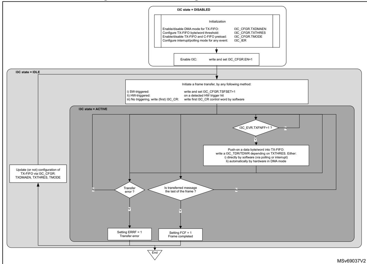
graph TD
    subgraph I3C_state_DISABLED [I3C state = DISABLED]
        Init[Initialization:
Enable/disable DMA mode for TX-FIFO: I3C_CFGR.TXDMAEN
Configure TX-FIFO byte/word threshold: I3C_CFGR.TXTHRES
Enable/disable TX-FIFO and C-FIFO preload: I3C_CFGR.TMODE
Configure interrupt/polling mode for any event: I3C_IER]
        EnableI3C[Enable I3C: write and set I3C_CFGR.EN=1]
    end

    subgraph I3C_state_IDLE [I3C state = IDLE]
        InitFrame[Initiate a frame transfer, by any following method:
i) SW-triggered: write and set I3C_CFGR.TSFSET=1
ii) HW-triggered: on a detected HW trigger bit
iii) No triggering, write (first) I3C_CR: write first I3C_CR control word by software]
    end

    subgraph I3C_state_ACTIVE [I3C state = ACTIVE]
        PollTXFNFF{I3C_EVR.TXFNFF=1?}
        PushData[Push-on a data byte/word into TX-FIFO:
write a I3C_TDR/TDWR depending on TXTHRES. Either:
i) directly by software (via polling or interrupt)
ii) automatically by hardware in DMA mode]
        TransError{Transfer error?}
        LastMessage{Is transferred message the last of the frame?}
        SetERRF[Setting ERRF = 1
Transfer error]
        SetFCF[Setting FCF = 1
Frame completed]
    end

    UpdateConfig[Update (or not) configuration of TX-FIFO via I3C_CFGR:
TXDMAEN, TXTHRES, TMODE]

    Init --> EnableI3C
    EnableI3C --> InitFrame
    InitFrame --> PollTXFNFF
    PollTXFNFF -- N --> PollTXFNFF
    PollTXFNFF -- Y --> PushData
    PushData --> TransError
    TransError -- Y --> SetERRF
    TransError -- N --> LastMessage
    LastMessage -- Y --> SetFCF
    LastMessage -- N --> PollTXFNFF
    SetERRF --> End{End}
    SetFCF --> End
    UpdateConfig --> I3C_state_IDLE
MSV69037V2
First, the software must initialize the TX-FIFO management via the following fields in the I3C_CFGR register:
- • TXDMAEN: enable/disable DMA mode for TX-FIFO
- • TXTHRES: push-on data byte(s) or word(s) into TX-FIFO
- • TMODE: enable/disable TX-FIFO and C-FIFO preload
Then, depending upon bit TXDMAEN in the I3C_CFGR register, the TX-FIFO is written either:
- • directly by the software (if TXDMAEN = 0) at the byte/word level:
- – via polling mode (TXFNFIE = 0 in the I3C_IER register): waiting for a next data byte/word is requested by the hardware (TXFNFF = 1 in the I3C_IER register) before an explicit write to the I3C_TDR or I3C_TDWR register, depending upon bit TXTHRES in the I3C_CFGR register
- – via enabled interrupt notification if TXFNFIE = 1
- • by the allocated DMA channel (if TXDMAEN = 1) to the corresponding DMA request from the I3C peripheral (i3c_tx_dma):
- – as configured at DMA block level, the DMA is automatically pushing-on/writing data bytes/words to the I3C_TDR or I3C_TDWR register (depending upon bit TXTHRES in the I3C_CFGR register) from its memory source buffer, until the frame completion (a stop is emitted on the I3C bus after the last message of the frame), unless a transfer error occurs.
An I3C message begins from a start or a repeated start, and ends with a stop or a repeated start. At message level, the last data byte/word to be transmitted is flagged by TXLASTF = 1 in the I3C_EVR register. When an I3C frame is described with multiple messages (separated by a repeated start), this event can be used by the software to update the pointer to the buffer where the byte(s)/word(s) of the next message is/are stored.
When frame completion is reported (FCF = 1 in the I3C_EVR register, and the corresponding interrupt is enabled), the TX-FIFO is empty.
If the TX-FIFO is empty and a data byte must be transmitted on the I3C bus, a TX-FIFO underrun is reported (ERRF = 1 in the I3C_EVR register and DOVR = 1 in the I3C_SER register). If enabled by ERRRIE = 1 in the I3C_IER register, an interrupt is generated.
The configuration for the TX-FIFO management can be modified when the I3C peripheral is not in active state.
When controller, if a transfer error occurs (ERRF = 1), the TX-FIFO is automatically flushed by the hardware.
No C-FIFO/TX-FIFO preload
As defined in Table 534 , C-FIFO size is two words, TX-FIFO size is 8 bytes.
When no C-FIFO/TX-FIFO preload is configured (TMODE = 0 in the I3C_CFGR register), the I3C peripheral emits a start on the I3C bus as soon as the first control word is written into the C-FIFO. Then, it decodes the I3C_CR register, and requires a next data byte/word to be written, if needed within this message. As soon as a next control word is detected as required by the hardware to be transmitted on the I3C bus (if a repeated start must be emitted on the I3C bus or if the C-FIFO gets available room), this control word is requested to be written into the C-FIFO until the last message (MEND = 1 in the I3C_CR register).
Similarly, as soon as another data byte/word is detected as required by the hardware to be transmitted on the I3C bus (if a repeated start must be emitted on the I3C bus, and if TX-FIFO is not full, and if data byte(s)/word(s) must be transmitted during this I3C message), this data byte/word must be written in the TX-FIFO.
C-FIFO and TX-FIFO preload
When C-FIFO/TX-FIFO preload is configured (TMODE = 1 in the I3C_CFGR register), before emitting a start on the bus, the I3C peripheral waits for loading as much as possible both the C-FIFO and the TX-FIFO, as follows:
- 1. Wait for a first control word to be written into the C-FIFO.
- 2. Wait for data byte(s)/word(s) to be written in the TX-FIFO, if any, as defined by the first control word (if RNW = 0 and DCNT[15:0] = 0 in the I3C_CR register), and up to the TX-FIFO size.
- 3. If TX-FIFO is not full and if the first control word is not the last of the frame (MEND = 0 in the I3C_CR register):
- a) Wait for a second control word to be written into the C-FIFO, then C-FIFO is full.
- b) If TX-FIFO is not full, wait for data byte(s)/word(s) to be written in the TX-FIFO, if any, as defined by the second control word (RNW = 0 and DCNT[15:0] = 0 in the I3C_CR register), and up to the TX-FIFO size.
Then, as soon as a next control word is detected as required by the hardware to be transmitted on the I3C bus (if a repeated start must be emitted on the I3C bus), this control
word is requested to be written into the C-FIFO until the last message (MEND = 1 in the I3C_CR register).
Similarly, as soon as a next data byte/word is detected as required by the hardware to be transmitted on the I3C bus (if a repeated start must be emitted on the I3C bus and if TX-FIFO is not full and if data byte(s)/word(s) are to be transmitted during this I3C message), this data byte/word must be written in the TX-FIFO.
49.10.3 RX-FIFO management, as controller
When controller, as shown in figures of Section 49.9 , RX-FIFO is used during any of the following transfers:
- • broadcast ENTDAA CCC ( Figure 664 )
- • direct CCC read ( Figure 663 ), including direct RSTACT CCC read ( Figure 665 )
- • private read ( Figure 670 )
- • legacy I2C read ( Figure 672 )
Figure 678 illustrates the management of the RX-FIFO for queuing and popping-out data bytes or word(s) as received from the I3C bus, when the I3C peripheral acts as controller.
Figure 678. RX-FIFO management, as controller
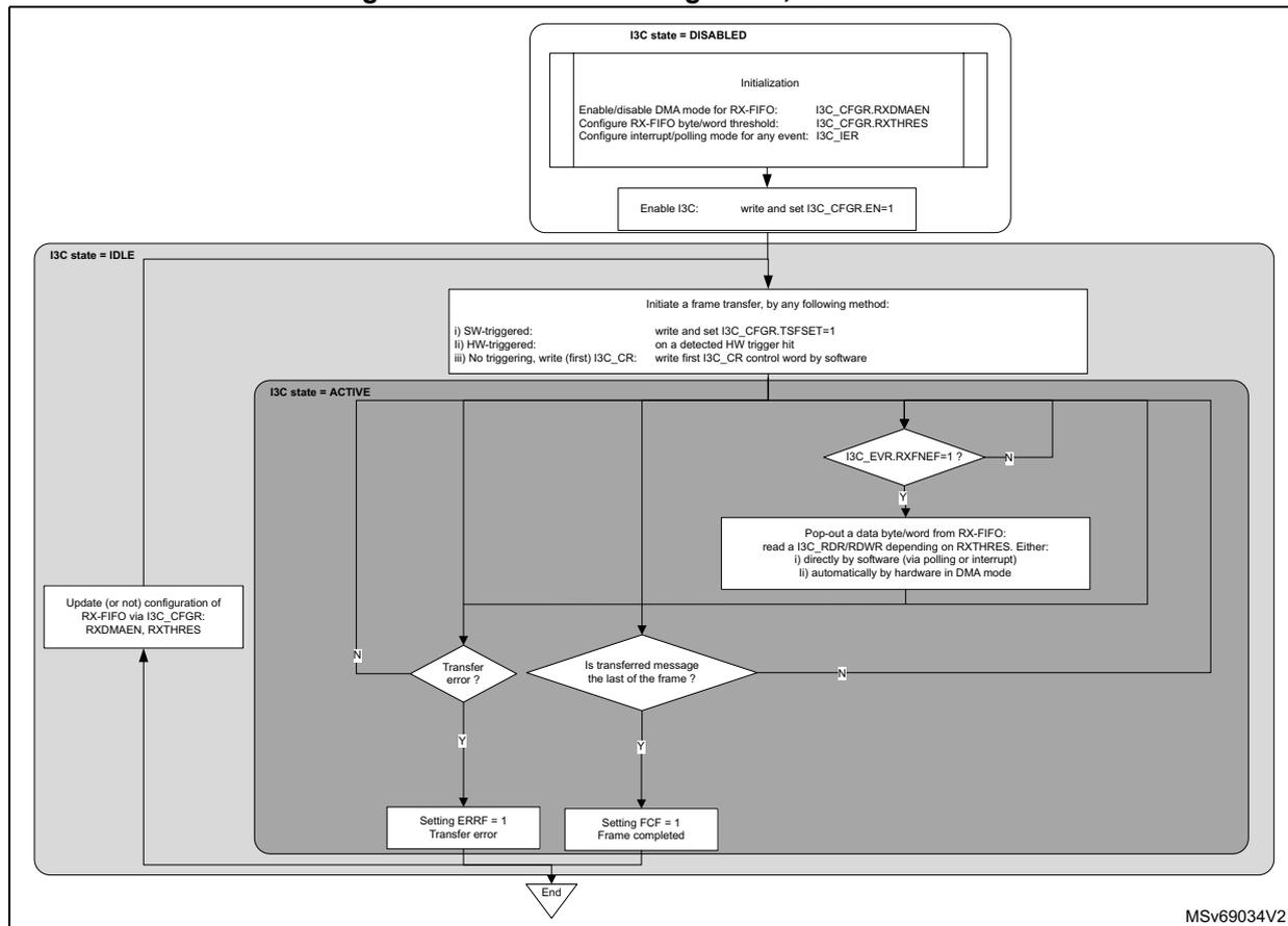
graph TD
    subgraph DISABLED [I3C state = DISABLED]
        Init[Initialization:
Enable/disable DMA mode for RX-FIFO: I3C_CFGR.RXDMAEN
Configure RX-FIFO byte/word threshold: I3C_CFGR.RXTHRES
Configure interrupt/polling mode for any event: I3C_IER]
        Enable[Enable I3C: write and set I3C_CFGR.EN=1]
    end

    subgraph IDLE [I3C state = IDLE]
        InitFrame[Initiate a frame transfer, by any following method:
i) SW-triggered: write and set I3C_CFGR.TSFSET=1 on a detected HW trigger hit
ii) HW-triggered: write first I3C_CR control word by software
iii) No triggering, write (first) I3C_CR: write first I3C_CR control word by software]
    end

    subgraph ACTIVE [I3C state = ACTIVE]
        CheckEmpty{I3C_EVR.RXFNEF=1?}
        PopOut[Pop-out a data byte/word from RX-FIFO:
read a I3C_RDR/RDWR depending on RXTHRES. Either:
i) directly by software (via polling or interrupt)
ii) automatically by hardware in DMA mode]
        CheckError{Transfer error?}
        CheckLast{Is transferred message the last of the frame?}
        SetError[Setting ERRF = 1
Transfer error]
        SetFCF[Setting FCF = 1
Frame completed]
    end

    DISABLED --> Init --> Enable --> IDLE
    IDLE --> InitFrame --> ACTIVE
    ACTIVE --> CheckEmpty --> PopOut --> CheckEmpty
    CheckEmpty -- N --> CheckLast
    CheckLast -- Y --> SetFCF
    CheckLast -- N --> CheckEmpty
    CheckError -- Y --> SetError
    SetError --> UpdateConfig[Update (or not) configuration of RX-FIFO via I3C_CFGR:
RXDMAEN, RXTHRES]
    UpdateConfig --> IDLE
    SetFCF --> End{End}
    SetError --> End
MSv69034V2
First, the software must initialize the RX-FIFO management via the following fields of the I3C_CFGFR register:
- • RXDMAEN: enable/disable DMA mode for RX-FIFO
- • RXTHRES: pop-out data byte(s) or word(s) from RX-FIFO
Then, depending on RXDMAEN, the RX-FIFO is read either:
- • directly by the software (RXDMAEN = 0) at the byte/word level:
- – via polling mode (RXFNEIE = 0 in the I3C_IER register): waiting for a next data byte/word is requested by the hardware (RXFNEF = 1 in the I3C_IER register) before an explicit read to the I3C_RDR or I3C_RDWR register, depending upon bit RXTHRES in the I3C_CFGFR register
- – via enabled interrupt notification if RXFNEIE = 1 in the I3C_IER register
- • by the allocated DMA channel (if RXDMAEN = 1) to the corresponding DMA request from the I3C peripheral (i3c_rx_dma):
- – as configured at DMA block level, the DMA automatically pops-out/reads data bytes/words from the I3C_RDR or I3C_RDWR register (depending upon bit RXTHRES), and writes them into its memory destination buffer, until the frame completion (a stop is emitted on the I3C bus after the last message of the frame), unless a transfer error occurs.
An I3C message begins from a start or a repeated start, and ends with a stop or a repeated start. At message level, the last received data byte/word from the I3C bus is flagged by IRXLASTF = 1 in the I3C_EVR register. When an I3C frame is described with multiple messages (separated by a repeated start), this event can be used by the software for updating the pointer to the buffer where is/are stored the data byte(s)/word(s) of the next message.
If RX-FIFO is full and a data byte is received on the I3C bus, an RX-FIFO overrun is reported (ERRF = 1 in the I3C_EVR register and DOVR = 1 in the I3C_SER register). If enabled by ERRRIE = 1 in the I3C_IER register, an interrupt is generated.
The configuration for the RX-FIFO management can be modified when the I3C peripheral is not in active state.
Early read termination from the target
A private read message can be early completed (also known as prematurely ended) by the addressed target.
- • If RXDMAEN = 1:
- – the software must allocate, for the DMA request i3c_rx_dma, a DMA channel x, capable of peripheral early termination (refer to DMA implementation section).
- – The software must configure the DMA channel x to enable the DMA peripheral-flow control mode via PFREQ = 1 in the DMA_CxTR2 register, to be able to perform a(n) (early or not) DMA block completion.
- – Then, on block completion, the software can read BR1.BNDT[15:0] in DMA_Cx and/or DMA_CxSAR register(s), to get the effective number of DMA transferred bytes.
- • If RXDMAEN = 0:
- – at message level, the last received data byte/word from the I3C bus is flagged by RXFNEF = 1 and RXLASTF = 1 in the I3C_EVR register.
In any case, if the S-FIFO is disabled (if SMODE = 0 in the I3C_CFGR register), the software is notified that an early read termination occurs by RXTGTENDF = 1 in the I3C_EVR register, and the corresponding interrupt if enabled. Then, software can read the status register I3C_SR to check information related to the last message ,and get the number of received data bytes on the prematurely ended read transfer (XDCNT[15:0] in the I3C_SR register).
In any case, if the S-FIFO is enabled (SMODE = 1 in the I3C_CFGR register), the software or the DMA (depending upon SDMAEN in the I3C_CFGR register) must read for each message the status register I3C_SR. The number of effective received data bytes on the prematurely ended read message is reported by XDCNT[15:0] (and then ABT = 1) in the I3C_SR register.
For more information, refer to I3C status register (I3C_SR) and Section 49.10.4 .
49.10.4 S-FIFO management, as controller
When controller, S-FIFO can be used by the software to be able to read the I3C status register (I3C_SR) for each transferred message.
Reading status register with disabled S-FIFO
If SMODE = 0 in the I3C_CFGR register, the S-FIFO is disabled and the status register can be read as a usual register:
- • the register content is overwritten by hardware when is transferee a new message
- • I3C_SR contains the status of the last transferred message
- • SCL clock is not stalled if status register is not read.
If SMODE = 0, for the specific case of a private read prematurely ended by the target:
- • the software is notified by the flag RXTGTENDF = 1 in the I3C_EVR register and the corresponding interrupt if enabled.
- • Then, until that the software has cleared the event flag write and set CRXTGTENDF = 1 in the I3C_CEVR register:
- – no more data byte can be received on the I3C bus and written by the hardware into I3C_RDR/I3C_RDWR registers
- – I3C_SR cannot be updated
- – SCL clock is stalled if needed
Typically, I3C_SR can be read when FCF = 1, or ERRF = 1, or RXTGTENDF = 1 in the I3C_EVR register. XDCNT[15:0] in the I3C_SR register can be read to get the effective number of received data bytes on a private read, after an early termination from the target (refer to Section 49.10.3 ).
Reading status register with enabled S-FIFO
If SMODE = 1 in the I3C_CFGR register, the S-FIFO is enabled. Figure 679 illustrates the management of the S-FIFO for queuing and popping-out a status word for each executed message on the I3C bus, when the I3C peripheral acts as controller.
Figure 679. S-FIFO management, as controller
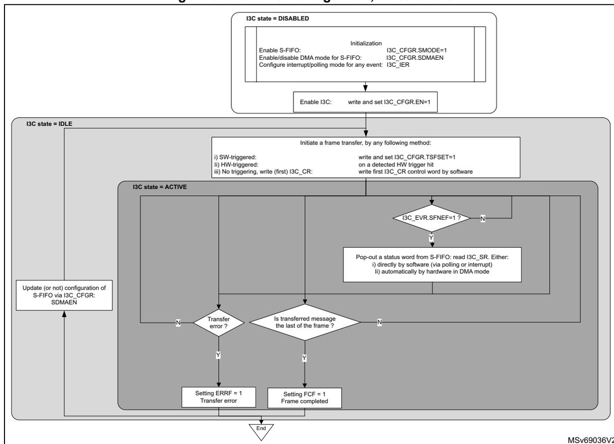
    graph TD
    subgraph DISABLED [I3C state = DISABLED]
    Init["Initialization:
Enable S-FIFO: I3C_CFGR.SMODE=1
Enable/disable DMA mode for S-FIFO: I3C_CFGR.SDMAEN
Configure interrupt/polling mode for any event: I3C_IER"]
    Enable["Enable I3C: write and set I3C_CFGR.EN=1"]
    Init --> Enable
    end

    Enable --> IDLE

    subgraph IDLE [I3C state = IDLE]
    Update["Update (or not) configuration of
S-FIFO via I3C_CFGR:
SDMAEN"]
    InitFrame["Initiate a frame transfer, by any following method:
i) SW-triggered: write and set I3C_CFGR.TSFSET=1
ii) HW-triggered: on a detected HW trigger hit
iii) No triggering, write (first) I3C_CR: write first I3C_CR control word by software"]
    end

    InitFrame --> ACTIVE

    subgraph ACTIVE [I3C state = ACTIVE]
    SFNEF_Check{"I3C_EVR.SFNEF=1 ?"}
    PopOut["Pop-out a status word from S-FIFO: read I3C_SR. Either:
i) directly by software (via polling or interrupt)
ii) automatically by hardware in DMA mode"]
    Error_Check{"Transfer
error ?"}
    Last_Check{"Is transferred message
the last of the frame ?"}
    SetERRF["Setting ERRF = 1
Transfer error"]
    SetFCF["Setting FCF = 1
Frame completed"]

    SFNEF_Check -- N --> SFNEF_Check
    SFNEF_Check -- Y --> PopOut
    PopOut --> Error_Check
    Error_Check -- Y --> SetERRF
    Error_Check -- N --> Last_Check
    Last_Check -- N --> SFNEF_Check
    Last_Check -- Y --> SetFCF
    end

    SetERRF --> Update
    SetFCF --> End((End))
    Update --> IDLE
MSV69036V2
First, the software must initialize the S-FIFO management via the SDMAEN field (enable/disable DMA mode for S-FIFO) in the I3C_CFGR register. Then, depending on SDMAEN, the S-FIFO is read either:
- • directly by the software (if SDMAEN = 0):
- – via polling mode (SFNEIE = 0 in the I3C_IER register): waiting for a next status word is requested by the hardware (SFNEF = 1 in the I3C_IER register) before an explicit read to the I3C_SR register
- – via enabled interrupt notification (SFNEIE = 1)
- • by the allocated DMA channel (if SDMAEN = 1) to the corresponding DMA request from the I3C peripheral (i3c_rs_dma):
- – as configured at DMA block level, the DMA is automatically popping-out/reading status words from the I3C_SR register and writing them into its memory destination buffer, until the frame completion (a stop is emitted on the I3C bus after the last message of the frame), unless a transfer error occurs.
Each message status must be read, else an overrun error is asserted by the hardware (ERRF = 1 in the I3C_EVR register and COVR = 1 in the I3C_SER register) when the S-FIFO is full and a next message status must be written. The corresponding interrupt is raised if enabled by ERRIE = 1 in the I3C_IER register.
The frame completion (FCF = 1 in the I3C_EVR register) is reported only when the S-FIFO is empty.
The configuration for the S-FIFO management can be modified when the I3C peripheral is not in active state.
49.11 I3C FIFOs management, as target
49.11.1 RX-FIFO management, as target
When target, as shown in figures of Section 49.9 , the RX-FIFO is used during any of the following received and acknowledged transfers:
- • broadcast DEFTGTS CCC ( Figure 668 )
- • broadcast DEFGRPA CCC ( Figure 669 )
- • private write ( Figure 671 )
Figure 680 illustrates the management of the RX-FIFO for queuing and popping-out data bytes or word(s) as received on the I3C bus, when the I3C peripheral acts as target.
Figure 680. RX-FIFO management, as target on the I3C bus
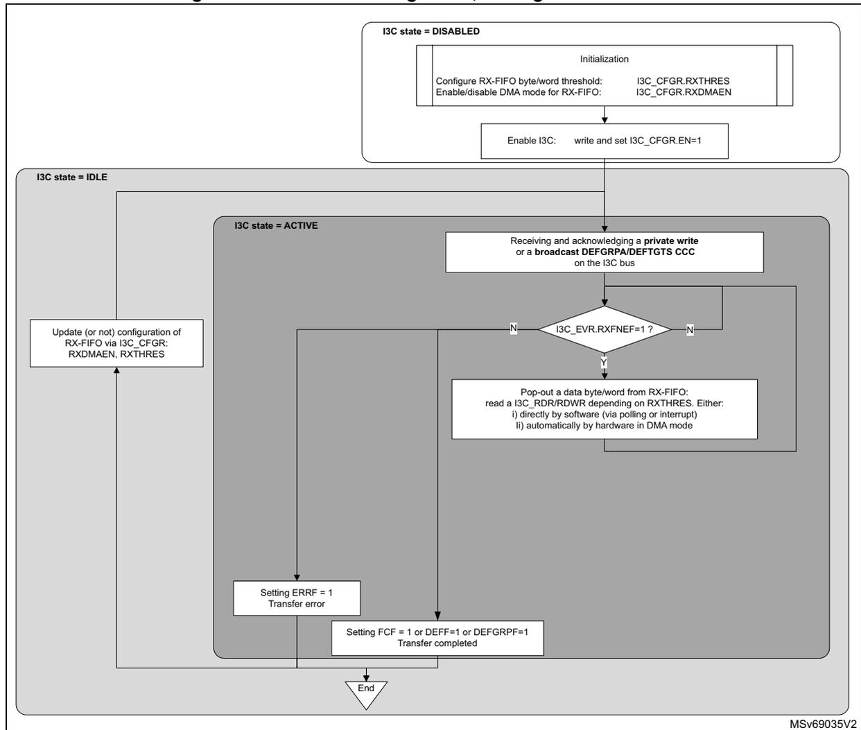
graph TD
    subgraph DISABLED [I3C state = DISABLED]
        Init[Initialization:
Configure RX-FIFO byte/word threshold: I3C_CFGR.RXTHRES
Enable/disable DMA mode for RX-FIFO: I3C_CFGR.RXDMAEN]
        Enable[Enable I3C: write and set I3C_CFGR.EN=1]
        Init --> Enable
    end
    Enable --> IDLE [I3C state = IDLE]
    subgraph IDLE [I3C state = IDLE]
        Update[Update (or not) configuration of RX-FIFO via I3C_CFGR:
RXDMAEN, RXTHRES]
    end
    Update --> ACTIVE [I3C state = ACTIVE]
    subgraph ACTIVE [I3C state = ACTIVE]
        Recv[Receiving and acknowledging a private write
or a broadcast DEFGRPA/DEFTGTS CCC
on the I3C bus]
        Recv --> Decision{I3C_EVR.RXFNEF=1?}
        Decision -- N --> Pop[Pop-out a data byte/word from RX-FIFO:
read a I3C_RDR/RDWR depending on RXTHRES. Either:
i) directly by software (via polling or interrupt)
ii) automatically by hardware in DMA mode]
        Pop --> Decision
        Decision -- Y --> Error[Setting ERRF = 1
Transfer error]
        Error --> Done[Setting FCF = 1 or DEFF=1 or DEFGRPF=1
Transfer completed]
        Done --> End[/End/]
    end
    Done --> IDLE
    End --> MSV[MSV69035V2]
First, the software must initialize the RX-FIFO management via the following I3C_CFGFR register fields:
- • RXDMAEN: enable/disable DMA mode for RX-FIFO
- • RXTHRES: pop-out data byte(s) or word(s) from RX-FIFO
Then, depending on RXDMAEN, the RX-FIFO is read either:
- • directly by the software (if RXDMAEN = 0) at the byte/word level:
- – via polling mode (RXFNEIE = 0 in the I3C_IER register): waiting for a next data byte/word is requested by the hardware (RXFNEF = 1 in the I3C_IER register) before an explicit read to the I3C_RDR or I3C_RDWR registers, depending upon RXTHRES in the I3C_CFGFR register
- – via enabled interrupt notification if RXFNEIE = 1
- • by the allocated DMA channel (if RXDMAEN = 1) to the corresponding DMA request from the I3C peripheral (i3c_rx_dma):
- – as configured at DMA block level, the DMA is automatically popping-out/reading data bytes/words from the I3C_RDR or I3C_RDWR register (depending upon RXTHRES) and writing them into its memory destination buffer, until the transfer completion (in the I3C_EVR register, FCF = 1 in case of private write, or GRPF = 1 in case of a DEFGRPA CCC, or DEFF = 1 in case of DEFTGTS CCC), unless a transfer error occurs.
If RX-FIFO is full and a new data byte is received on the I3C bus, a RX-FIFO overrun is reported (ERRF = 1 in the I3C_EVR register and DOVR = 1 in the I3C_SER register) and the corresponding interrupt if enabled.
When the transfer is completed (in the I3C_EVR register, FCF = 1, or GRPF = 1, or DEFF = 1):
- • RX-FIFO is empty
- • Until software has not processed the RX data buffer corresponding to the completed or private write / DEFTGTS / DEFGRPA transfer (meaning until software has not cleared the corresponding flag write and set CFCF / CDEFF / CGRPF to 1 in the I3C_CEVR register), if a next private write / DEFTGTS CCC / DEFGRPA CCC is received and a data byte must be written by the hardware into the RX-FIFO, a transfer error is reported with a RX-FIFO overrun (ERRF = 1 in the I3C_EVR register and DOVR = 1 in the I3C_SER register) and the corresponding interrupt if enabled.
The configuration for the RX-FIFO management can be modified when the I3C peripheral is not in active state.
49.11.2 TX-FIFO management, as target
Main scheme
When target, as shown in figures of Section 49.9 , the TX-FIFO is used only during a private read ( Figure 671 ).
Figure 681 illustrates the management of the TX-FIFO for queuing and pushing-on data bytes or word(s) to be transmitted on the I3C bus, when the I3C peripheral acts as target.
Figure 681. TX-FIFO management with I3C_TGTTDR, as target on the I3C bus
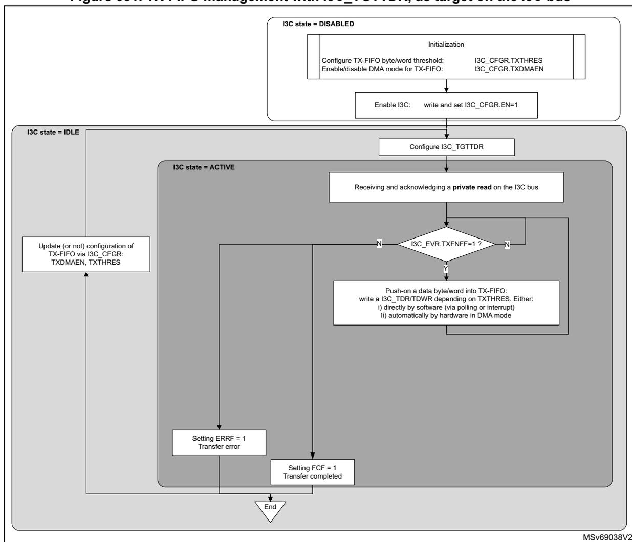
graph TD
    subgraph I3C_state_DISABLED [I3C state = DISABLED]
        Init["Initialization
Configure TX-FIFO byte/word threshold: I3C_CFGR.TXTHRES
Enable/disable DMA mode for TX-FIFO: I3C_CFGR.TXDMAEN"]
        EnableI3C["Enable I3C: write and set I3C_CFGR.EN=1"]
        Init --> EnableI3C
    end
    EnableI3C --> ConfigTGTTDR["Configure I3C_TGTTDR"]
    subgraph I3C_state_IDLE [I3C state = IDLE]
        ConfigTGTTDR
        UpdateCFG["Update (or not) configuration of TX-FIFO via I3C_CFGR:
TXDMAEN, TXTHRES"]
    end
    ConfigTGTTDR --> Receiving["Receiving and acknowledging a private read on the I3C bus"]
    subgraph I3C_state_ACTIVE [I3C state = ACTIVE]
        Receiving --> Decision1{"I3C_EVR.TXFNFF=1 ?"}
        Decision1 -- Y --> PushData["Push-on a data byte/word into TX-FIFO:
write a I3C_TDR/TDWR depending on TXTHRES. Either:
i) directly by software (via polling or interrupt)
ii) automatically by hardware in DMA mode"]
        PushData --> Decision1
        Decision1 -- N --> Decision2{"ERRF=1 ?"}
        Decision2 -- Y --> Error["Setting ERRF = 1
Transfer error"]
        Decision2 -- N --> Decision3{"FCF=1 ?"}
        Decision3 -- Y --> Completed["Setting FCF = 1
Transfer completed"]
        Error --> End
        Completed --> End
        Error --> UpdateCFG
        Completed --> UpdateCFG
    end
    End --> MSv69038V2[MSv69038V2]
First, the software must initialize the TX-FIFO management and write I3C_CFGR with
- • TXDMAEN: enable/disable DMA mode for TX-FIFO
- • TXTHRES: push-on data byte(s) or word(s) to TX-FIFO
Then, before receiving a private read on the I3C bus, the software must configure the I3C target transmit configuration register (I3C_TGTTDR) to preload the TX-FIFO with a number of data bytes (write TGTTDCNT[15:0] and PRELOAD = 1 in a single access), so that data bytes from the target are ready to be transmitted on the serial bus:
- • If PRELOAD = 1 and TGTTDCNT[15:0] > TX-FIFO size, TX-FIFO is first preloaded up to the FIFO size.
- • If PRELOAD = 1 and TGTTDCNT[15:0] ≤ TX-FIFO size, TX-FIFO is preloaded up to TGTTDCNT[15:0].
Note: TX-FIFO size is 8 bytes (refer to Table 534).
Depending upon TXDMAEN, the TX-FIFO is preloaded either:
- • directly by the software (TXDMAEN = 0) at the byte/word level:
- – via polling mode (TXFNFIE = 0 in the I3C_IER register): waiting for a next data byte/word is requested by the hardware (TXFNFF = 1 in the I3C_IER register) before an explicit write to the I3C_TDR or I3C_TDWR register, depending upon TXTHRES in the I3C_CGFR register
- – via enabled interrupt notification if TXFNFIE = 1
- • by the allocated DMA channel (TXDMAEN = 1) to the corresponding DMA request from the I3C peripheral (i3c_tx_dma):
- – as configured at DMA block level, the DMA is automatically pushing-on/writing data bytes/words to the I3C_TDR or I3C_TDWR register (depending upon TXTHRES) from its memory source buffer, until the transfer completion (FCF = 1 in the IEC_EVR register), unless a transfer error occurs.
Then, in the same way, either directly by the software or by the allocated DMA channel, if there are remaining TGTDCNT[15:0] in the I3C_TGTDR register to be loaded into TX-FIFO for continuing the private read (set PRELOAD = 1 and TGTDCNT[15:0] > TX-FIFO size), and provided that the private read is not yet completed by the controller:
- – If TXTHRES = 0: when a byte is transmitted on the serial bus, a next byte is preloaded into TX-FIFO
- – If TXTHRES = 1: when four bytes are transmitted on the serial bus, the next word is preloaded into TX-FIFO.
The private read transfer is completed (FCF = 1 in the I3C_EVR register) when either the target or the controller first terminates the data byte transfer.
On transfer completion, the software can:
- • read XDCNT[15:0] in the I3C_SR register: the effective number of transmitted data bytes
- • read TGTDCNT[15:0] in the I3C_TGTDR register: the remaining number of bytes to be loaded and transmitted on the serial bus
- • flush TX-FIFO: write and set (or not) TXFLUSH = 1 in the I3C_CGFR register, continue (or not) for another read, depending upon the user application
If TX-FIFO is empty and a data byte must be transmitted on the serial bus, a TX-FIFO underrun is reported (ERRF = 1 in the I3C_EVR register and DOVR = 1 in the I3C_SER register). If enabled by ERRRIE = 1 in the I3C_EVR register, an interrupt is generated.
The configuration for the TX-FIFO management can be modified when the I3C peripheral is not in active state.
Alternative without I3C_TGTDR, if less bytes than the TX-FIFO size
Alternatively to the use of the I3C_TGTDR register, as shown in the Figure 682 , when the DMA is not used (TDMAEN = 0), provided that the number of data bytes to be read on the serial bus is less than the TX-FIFO size, the software can directly prepare and fill the TX-FIFO with the number of bytes to be read directly by the software, by successive writes to the I3C_TDR or I3C_TDWR, depending upon TXTHRES.
Figure 682. TX-FIFO management by software without I3C_TGTTDR if reading less bytes than TX-FIFO size, as target
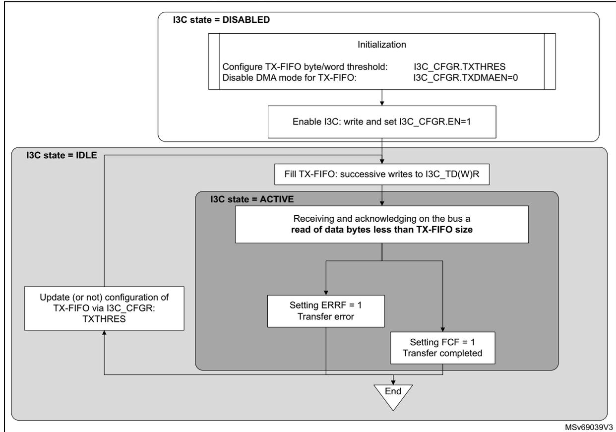
graph TD
    subgraph I3C_state_DISABLED [I3C state = DISABLED]
        Init[Initialization<br/>Configure TX-FIFO byte/word threshold: I3C_CFGR.TXTHRES<br/>Disable DMA mode for TX-FIFO: I3C_CFGR.TXDMAEN=0]
        Enable[Enable I3C: write and set I3C_CFGR.EN=1]
        Init --> Enable
    end
    Enable --> I3C_state_IDLE
    subgraph I3C_state_IDLE [I3C state = IDLE]
        Fill[Fill TX-FIFO: successive writes to I3C_TD(W)R]
        Update[Update (or not) configuration of<br/>TX-FIFO via I3C_CFGR:<br/>TXTHRES]
        Fill --> I3C_state_ACTIVE
    end
    subgraph I3C_state_ACTIVE [I3C state = ACTIVE]
        Read[Receiving and acknowledging on the bus a<br/>read of data bytes less than TX-FIFO size]
        Error[Setting ERRF = 1<br/>Transfer error]
        Done[Setting FCF = 1<br/>Transfer completed]
        Read --> Error
        Read --> Done
    end
    Done --> End{End}
    Update --> Fill
    Error --> End
    Done --> End
MSv69039V3
49.12 I3C error management
49.12.1 Controller error management
Table 543 enumerates the I3C bus error conditions, and, for each of them, the corresponding detection, action and reporting when the I3C peripheral acts as controller.
Table 543. I3C controller error management
| Error type | Description | Error detection | Controller action | Reported error (1) |
|---|---|---|---|---|
| CE0 | Illegally formatted CCC (e.g. less returned data byte(s)) | Prematurely ended read data by target on a direct CCC read (2) | Hardware emits a stop. | ERRF = 1 and PERR = 1 and CODERR[3:0] = 0000 |
Table 543. I3C controller error management (continued)
| Error type | Description | Error detection | Controller action | Reported error (1) |
|---|---|---|---|---|
| CE1 | Monitoring error | An incorrect ACK is detected at the end of a legacy I 2 C read | Hardware keeps SCL running for nine clock cycles and another byte to be possibly exchanged, then emits again a NACK, followed by a stop. | ERRF = 1 and PERR = 1 and CODERR[3:0] = 0001 |
| Restart or stop cannot be generated at the end of an I3C SDR read | SCL is kept running. Software can stop SCL by writing a control word with MTYPE[3:0] = 0000 in the I3C_CR register (header message), then must typically wait at least 150 µs before emitting another message. | |||
| After a CE1 error, a start cannot be generated | ||||
| CE2 | No response to broadcast address (0b111_1110) | Header (0b111_1110 + RnW = 0) is detected as NACK-ed during a message different from escalation fault or reset pattern message | Hardware emits an HDR exit pattern followed by a stop. | ERRF = 1 and PERR = 1 and CODERR[3:0] = 0010 |
| CE3 | Failed controller hand-off | New controller has not driven SCL low after having SDA low (after a start via a test header or a start request from a target) and after the delay time defined by its activity state has elapsed | Hardware emits a start + 0b111_1110 + RnW = 0, followed by ACK/NACK from target(s), then stops. | ERRF = 1 and PERR = 1 and CODERR[3:0] = 0011 |
| - | Incorrect returned 7-bit target address with parity bit on a GETACCCR CCC | Incorrect dynamic address and/or parity bit is detected | Hardware cancels the GETACCCR CCC by emitting a Restart + 0b111_1110 + RnW = 0, followed by ACK/NACK from target(s), then stops. | ERRF = 1 and DERR = 1 |
| - | Addressed target is NACK-ed on a direct CCC read for the first time | NACK is detected | Hardware performs a single-retry by emitting a Restart + 7-bit same target address + RnW = 1. | - |
| - | Addressed target is NACK-ed on either a direct CCC write, an I3C private read/write, a legacy I 2 C, or a direct CCC read for the second time | NACK is detected | Hardware emits a stop. | ERRF = 1 and ANACK= 1 |
Table 543. I3C controller error management (continued)
| Error type | Description | Error detection | Controller action | Reported error (1) |
|---|---|---|---|---|
| - | Assigned/transmitted dynamic address with parity bit is NACK-ed on a ENTDAA CCC for the first time | NACK is detected | Hardware performs a single-retry assignation loop by emitting a Restart + 0b111_1110 + RnW = 1, followed by an ACK and 8-byte read data from the (most-priority) target, followed by the assigned address + parity bit. | - |
| - | Assigned/transmitted dynamic address with parity bit is NACK-ed on a ENTDAA CCC for the second time | NACK is detected | Hardware emits a stop. | ERRF = 1 and DNACK= 1 |
| - | Write data is NACK-ed on a legacy I2C write | |||
| - | Control word, status word, transmitted data or read data is not written/read in time vs. I3C bus timings | SCL stall timeout | Hardware emits a stop. | ERRF = 1 and (COVR = 1 or DOVR = 1) |
- 1. ERRF in the I3C_EVR register, PERR, CODERR[3:0], DERR, ANACK, DNACK, COVR, and DOVR in the I3C_SER register.
- 2. MIPI v1.1: on a GETCAPS CCC, the number of received data bytes can be 2, 3 or 4. However a target compliant with MIPI v1.0 can return only the first byte as per previously named GETHDRCAP CCC. As a result, CE0 is not generated if the number is lower than 4.
On a GETMXDS CCC, the number of received data bytes can be 2 or 5. CE0 is not generated if the number is lower than 5.
49.12.2 Target error management
Table 544 enumerates the I3C bus error conditions, the corresponding detection, action, and reporting when the I3C peripheral acts as target.
Table 544. I3C target error management
| Error type | Description | Error detection | Next (when emitted by the controller) | Reported error (1) |
|---|---|---|---|---|
| TE0 | Invalid broadcast address (0b111_1110+RnW = 0) or Invalid 7-bit dynamic address + RnW = 1 after DAA assignment | A forbidden address is detected after a start or a repeated start | Hardware waits for an HDR exit pattern | ERRF = 1 and PERR = 1 and ODERR[3:0] = 1000 |
| TE1 | CCC code | A CCC code is detected with a parity error | ERRF = 1 and PERR = 1 and ODERR[3:0] = 1001 |
Table 544. I3C target error management (continued)
| Error type | Description | Error detection | Next (when emitted by the controller) | Reported error (1) |
|---|---|---|---|---|
| TE2 | Write data | A write data byte is detected with a parity error on an I3C private write message | Hardware waits for a stop or a repeated start | ERRF = 1 and PERR = 1 and ODERR[3:0] = 1010 |
| TE3 | Assigned address during dynamic address arbitration | Assigned dynamic address is detected with a parity error on a ENTDAA CCC | ERRF = 1 and PERR = 1 and ODERR[3:0] = 1011 | |
| TE4 | 0b111_1110 + RnW = 1 missing after Sr during dynamic address arbitration | Missing {0b111_1110 + RnW = 1} after Sr during dynamic address arbitration is detected | ERRF = 1 and PERR = 1 and ODERR[3:0] = 1100 | |
| TE5 | Transaction after detecting CCC | Invalid CCC direction is detected vs. direction provided during address phase, on a CCC direct read/write | ERRF = 1 and PERR = 1 and ODERR[3:0] = 1101 | |
| TE6 | Monitoring error of I3C bus | SDA is detected as driven at unexpected value on an data read (during a CCC direct read or a private read or an IBI) | Hardware releases SDA, then waits for a stop or a repeated start | ERRF = 1 and PERR = 1 and ODERR[3:0] = 1110 |
| - | Monitoring SCL on an SDR data read | SCL is detected as stable for more than 125 µs on an SDR data read (during a CCC direct read or a private read or an IBI) | ERRF = 1 and STALL = 1 | |
| - | Data to be transmitted not written/available in time vs. I3C bus timings | Data to be transmitted not written by software or DMA in due time on a private read | Hardware detects a stop or a repeated start | ERRF = 1 and DOVR = 1 |
| - | Received data cannot be registered in time vs. I3C bus timings | Received data is not read by software or DMA in due time on a private write or a DEFTGTS or a DEFGRPA CCC |
1. ERRF in the I3C_EVR register, PERR, ODERR[3:0], STALL, and DOVR in the I3C_SER register.
49.13 I3C wake-up from low-power mode(s)
49.13.1 Wake-up from Stop
The user must first configure the reset and clock controller (RCC) to set up the clock data path down to the I3C peripheral: to select the source oscillator for the I3C kernel clock, the source oscillator for the I3C APB clock, and to set the clocks frequency. At initialization via the RCC, the user must enable the I3C clocks for a given I3C peripheral to be functional, separately for Run/Sleep mode and for Stop mode. For more details about RCC programming, refer to Section Reset and clock control (RCC).
The I3C hardware automatically manages its own clocks gating and generates a separated clock request output signal to the RCC for its kernel clock and its APB clock, whenever the device is in Run, Sleep or Stop mode.
When entering a Stop mode, the \( V_{CORE} \) domain is supplied, by default any clock oscillator is disabled, and in any case, neither the system clock nor a peripheral clock is running in the domain.
As controller: wake-up on an IBI without MDB, a hot-join request or a controller-role request
When the peripheral acts as controller, before the product enters a low-power mode, the software must issue an ENTASx CCC, generally with \( x = 0, 1, 2 \) or \( 3 \) , to inform targets that the I3C controller is not expected to exit from idle state neither to communicate on the I3C bus before an interval of, respectively, \( 1 \mu s \) , \( 100 \mu s \) , \( 2 ms \) or \( 50 ms \) , has elapsed. This delay defines the \( T_{CAS} \) delay for the controller to set the SCL bus clock low and running, after a start condition. More specifically for a Stop mode, the CCC must be restricted to an ENTASx with the value \( x = 1, 2 \) , or \( 3 \) .
The general scheme for the I3C wake-up from Stop is the following:
- 1. First the I3C peripheral requests its kernel clock to the system:
- – On a detected start condition on the I3C bus (SDA line is detected to be driven low while SCL is high).
- – As controller, as initiated by an external I3C target device for a hot-join/in-band interrupt/controller-role request. Once the kernel clock is provided and running, the I3C hardware uses an internal timer to wait for the corresponding \( T_{CAS} \) time to elapse, then drives low SCL and continues toggling SCL to let the target perform its hot-join/in-band interrupt/controller-role request on the I3C bus.
- 2. The system enables the source oscillator of the I3C kernel clock, and the clock gets ready (after few microseconds from HSI). The user can keep the source oscillator ON in Stop mode to reduce this startup latency, at the expense of power consumption.
- – The I3C peripheral maintains the kernel clock request until the generation of the Stop condition on the I3C bus.
- 3. After that the kernel clock is running, as controller the I3C peripheral requests its APB clock to the system:
- – On the ACKed address of a received IBI request (
Figure 673
), and it maintains the APB clock request until that IBIF is cleared.
If the IBI is without MDB: a Stop is normally generated on the I3C bus, even if the APB clock is not yet provided. - – On the ACKed address of a received controller-role request ( Figure 674 ), and it maintains the APB clock request until that CRF is cleared.
- – On the ACKed address of a hot-join request ( Figure 675 ), and it maintains the APB clock request until that HJF is cleared.
- – On the ACKed address of a received IBI request (
Figure 673
), and it maintains the APB clock request until that IBIF is cleared.
- 4. The system is notified of the I3C APB clock request, and the power management unit of the PWR module is awaken.
- 5. An additional delay may be needed for the regulator, if it must increase the voltage for Run mode.
- 6. The system enables the system clock that drives the APB clock. There is an additional delay if the selected oscillator source for the system and APB clocks is not the same as the one driving the I3C kernel clock. If so, the system enables the source oscillator of the system clock, which gets ready after a delay.
- 7. With the APB clock running, the I3C peripheral can log the I3C transfer in its status and data registers. When the bus transfer is completed, the I3C peripheral generates the corresponding flag (IBIF/CRF/HJF), and the enabled interrupt can wake up the CPU.
As target: wake-up on a I3C reset pattern
The target reset pattern is a specific scheme for a controller to wake up and possibly reset a target from a low power mode. It consists both in the RSTACT CCC and in the in-band reset pattern generation.
As target, the sequence for the I3C wake-up from Stop on a reset pattern is the following:
- 1. When the I3C peripheral detects a reset pattern on the bus (14 SDA transitions while SCL is kept low), it requests its APB clock to the system to set the RSTF flag of the I3C_EVR register
- 2. The system is notified of the I3C APB clock request, and the power management unit of the PWR module is awaken (after few microseconds).
- 3. An additional delay may be needed for the regulator, if it must increase the voltage for Run mode.
- 4. The system enables the source oscillator of the system clock, which gets ready after few microseconds.
- 5. With the APB clock running, the I3C peripheral can raise the RSTF flag of the I3C_EVR register, and the enabled interrupt can wake up the CPU.
As target: wake-up on a missed start on the I3C bus
- 1. The I3C peripheral requests its kernel clock to the system:
- – On a detected start condition on the serial bus (SDA line is detected to be driven low while SCL is high)
- – If the kernel clock is not provided before that SCL is driven low by the external controller, then the I3C target detects that a bus start is missed and waits for the kernel clock to be provided. A controller message that is specifically addressed to this low-power device may have been missed (and NACKed). However the I3C peripheral can also detect a missed start if the controller started a CCC or private or legacy I 2 C message to another addressed target, or if another target initiated a start for an IBI/CR/HJ request.
- 2. The system enables the source oscillator of the I3C kernel clock, and the clock gets ready (after few microseconds if HSI). The user may keep the source oscillator ON in Stop mode to reduce this startup latency, at the expense of power consumption. Especially if the controller is in an Activity State of x = 0 (with a 1 µs T CAS latency).
- 3. After that the kernel clock is running, as target, the I3C peripheral requests its APB clock to the system to raise the WKPF flag:
- 4. The system is notified of the I3C APB clock request, and the power management unit of the PWR module is awaken (after few microseconds).
- 5. An additional delay may be needed for the regulator, if it must increase the voltage for Run mode.
- 6. The system enables the system clock, which drives the APB clock. There is an additional delay if the selected oscillator source for the system and APB clocks is not the same as the one driving the I3C kernel clock. If so, the system enables the source oscillator of the system clock, which gets ready after few microseconds.
- 7. With the APB clock running:
- – The missed start flag (WKPF of the I3C_EVR register) is raised if it occurred, and the enabled interrupt can wake up the CPU. It is then known that a serial bus transaction was missed, but not whether the target was addressed or not. The software should use a timeout to return to Stop mode, if it is not addressed by the controller again within this interval.
49.14 I3C in low-power modes
Table 545. Effect of low-power modes
| Mode | Description |
|---|---|
| Sleep | No effect. I3C interrupts cause the device to exit Sleep mode. |
| Stop (1) | The content of the I3C registers is kept when entering Stop mode. I3C hardware manages automatically its own clocks gating and generates, for its kernel clock and APB clock, a clock request output signal to the RCC. I3C interrupts can cause the device to wake up and exit Stop mode. |
| Standby | The I3C peripheral is powered down and must be reinitialized after exiting Standby mode. |
- 1. Refer to Table 533 to know if Stop mode is supported, and which one.
49.15 I3C interrupts
Table 546. I3C interrupt requests
| Interrupt acronym | Interrupt event | Used as | Interrupt enable: field in I3C_IER | Event flag: field in I3C_EVR | Event clear method: write 1 to field in I3C_CEVR | ||
|---|---|---|---|---|---|---|---|
| Controller | Target | ||||||
| I3C | EVT | A control word is requested | X | - | CFNFIE | CFNFF | - |
| A status word is available | X | - | SFNEIE | SFNEF | - | ||
| Data to be transmitted are requested | X | X | TXNFIE | TXNFF | - | ||
| Received data are available | X | X | RXFNEIE | RXFNEF | - | ||
| Controller: frame transfer is completed Target: private transfer is completed | X | X | FCIE | FCF | CFCF | ||
| A private read transfer is prematurely ended by the target (and SMODE = 0 in the I3C_CFGGR register) | X | - | RXTGTENDIE | RXTGTENDF | CRXTGTENDF | ||
| An IBI request is received | X | - | IBIIE | IBIF | CIBIF | ||
| A controller-role request is received | X | - | CRIE | CRF | CCRF | ||
| A hot-join request is received | X | - | HJIE | HJF | CHJF | ||
| IBI request is completed | - | X | IBIENDIE | IBIENDF | CIBIENDF | ||
| Serial bus start is missed | - | X | WKPIE | WKPF | CWKPF | ||
| Direct GETACCR CCC is received | - | X | CRUPDIE | CRUPDF | CCRUPDF | ||
| Direct GETSTATUS CCC is received | - | X | STAIE | STAF | CSTAF | ||
| Any direct GETxxx CCC (except GETSTATUS) is received | - | X | GETIE | GETF | CGETF | ||
| Dynamic address is updated (broadcast ENTDAA/RSTDAA or direct SETNEWDA is received) | - | X | DAUPDIE | DAUPDF | CDAUPDF | ||
| Direct SETMWL CCC is received | - | X | MWLUPDIE | MWLUPDF | CMWLUPDF | ||
| Direct SETMRL CCC is received | - | X | MRLUPDIE | MRLUPDF | CMRLUPDF | ||
| A reset pattern is detected | - | X | RSTIE | RSTF | CRSTF | ||
| Bus activity state is updated (direct/broadcast ENTASx CCC is received) | - | X | ASUPDIE | ASUPDF | CASUPDF | ||
| Broadcast/direct ENEC/DISEC CCC is received | - | X | INTUPDIE | INTUPDF | CINTUPDF | ||
| Broadcast DEFTGTS CCC is received | - | X | DEFIE | DEFF | CDEFF | ||
| Broadcast DEFGRA CCC is received | - | X | GRPIE | GRPF | CGRPF | ||
| ERR | An error occurred | X | X | ERRIE | ERRF | CERRF | |
49.16 I3C registers
The I3C registers must be accessed with a 32-bit word aligned address.
Note: I3C_RDR and I3C_TDR registers must be accessed with a single significant LSB data byte for, respectively, reading RX-FIFO and writing TX-FIFO.
49.16.1 I3C message control register (I3C_CR)
Address offset: 0x000
Reset value: 0x0000 0000
This register must be used to control the message to emit on the I3C bus:
- • when I3C acts as controller (bit[30] = MTTYPE[3] = 0): if there is no CCC code to be emitted bits[29:27] = MTTYPE[2:0] differ from 110; else the alternate register description Section 49.16.2 must be considered.
- • when I3C acts as target (bit[30] = MTTYPE[3] = 1).
When I3C acts as controller:
- • If the control FIFO (C-FIFO) is not full (CFNFF = 1 in the I3C_EVR register), writing into this register means pushing a new control word into the C-FIFO; either by software, or automatically by DMA, as defined by CDMAEN in the I3C_CFGR register.
- • If C-FIFO is empty and a restart must be emitted with a new control word, the I3C hardware asserts the control FIFO error underrun flag (COVR = 1 in the I3C_SER register). If enabled by ERRRIE = 1 in the I3C_IER register, an interrupt is generated.
- • After the last message of the frame is completed (a message with MEND = 1 in the I3C_CR register), the I3C hardware asserts the frame completed flag (FCF = 1 in the I3C_EVR register) and the corresponding interrupt, if enabled.
When I3C acts as target, this register is used in register mode:
- • Software writes into this register to initiate a command (IBI, controller-role or hot-join request) on the I3C bus.
- • C-FIFO is disabled, and there is no DMA mode neither for control words.
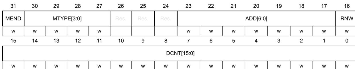
| 31 | 30 | 29 | 28 | 27 | 26 | 25 | 24 | 23 | 22 | 21 | 20 | 19 | 18 | 17 | 16 |
| MEND | MTYPE[3:0] | Res. | Res. | Res. | ADD[6:0] | RNW | |||||||||
| w | w | w | w | w | w | w | w | w | w | w | w | w | |||
| 15 | 14 | 13 | 12 | 11 | 10 | 9 | 8 | 7 | 6 | 5 | 4 | 3 | 2 | 1 | 0 |
| DCNT[15:0] | |||||||||||||||
| w | w | w | w | w | w | w | w | w | w | w | w | w | w | w | w |
Bit 31 MEND : Message end type/last message of a frame (when the I3C acts as controller)
0: this message from controller is followed by a repeated start (Sr), before another message must be emitted
1: this message from controller ends with a stop (P), being the last message of a frame
Bits 30:27 MTYPE[3:0] : Message type (whatever I3C acts as controller/target)
Condition: when I3C acts as I3C controller
0000: SCL clock is forced to stop until a next control word is executed
Bits[26:0] are ignored. On a CE1 error detection (ERRF = 1 in the I3C_EVR register and CODERR[3:0] = 0001 in the I3C_SER register) where a start/restart/stop is prevented from being generated, the software must use this message type for SCL “stuck at” recovery. Refer to Table 543 .
0001: header message
Bits[26:0] are ignored. If the addressed target is not responding with an ACK to a private/direct message, as an escalation stage after a failed GETSTATUS tentative, the software must program this with EXITPTRN = 1 in the I3C_CFGR register, so that an HDR exit pattern is emitted on the bus, whatever the header is ACK-ed or NACK-ed (to avoid the target to consider that the I3C bus is in HDR mode). Refer to Table 543 and MIPI specification about escalation handling.
0010: private message (refer to Figure 670 )
Bits[23:17] (ADD[6:0]) are the emitted 7-bit dynamic address.
Bit[16] (RNW) is the emitted RnW bit.
Bits[15:0] (DCNT[15:0]) are the number of programmed data bytes.
The transferred private message is:
- – {S / S + 0b111_1110 + RnW = 0 + Sr/Sr+*} + 7-bit DynAddr + RnW + (8-bit Data + T)* + Sr/P.
- – After an S (start), depending upon bit NOARBH in the I3C_CFGR register, the arbitrable header (0b111_1110 + RnW = 0) is inserted or not.
- – Sr*: after an Sr (repeated start), the hardware automatically inserts (0b111_1110 + RnW = 0) if needed, if it follows a previous message without ending by a P (stop).
0011: direct message (second part of an I3C SDR direct CCC command) (refer to Figure 663 )
Bits[23:17] (ADD[6:0]) are the emitted 7-bit dynamic address.
Bit[16] (RNW) is the emitted RnW bit.
Bits[15:0] (DCNT[15:0]) are the number of programmed data bytes.
The transferred direct message is: Sr + 7-bit DynAddr + RnW + (8-bit Data + T)* + Sr/P
0100: legacy I 2 C message (refer to Figure 672 )
Bits[23:17] (ADD[6:0]) are the emitted 7-bit static address.
Bit[16] (RNW) is the emitted RnW bit.
Bits[15:0] (DCNT[15:0]) are the number of programmed data bytes.
The transferred legacy I 2 C message is:
- – {S / S + 0b111_1110 + RnW = 0 + Sr/Sr+*} + 7-bit StaAddr + RnW + (8-bit data + T)* + Sr/P.
- – After an S, depending on NOARBH, the arbitrable header (0b111_1110 + RnW = 0) is inserted or not.
- – Sr*: after an Sr (repeated start), the hardware automatically inserts (0b111_1110 + RnW = 0) if needed (if it follows a previous message without ending by a P (stop)).
Others: reserved
Condition: when I3C acts as I3C target
1000: hot-join request (W) (refer to Figure 674 )
The transferred hot-join request is {S +} 0b000_0010 addr + RnW = 0.
Writing the control word initiates the hot-join request if target is allowed to do so (HJEN = 1 in the I3C_DEVR0 register), either actively after a bus idle condition via the hardware issuing a start request (SDA low) and waiting for the controller to activate SCL clock, or passively if the controller initiates a concurrent message.
1001: controller-role request (W) (refer to Figure 675 )
The transferred controller-role request is {S +} DA[6:0] + RnW = 0 (DA in the I3C_DEVR0 register)
Writing the control word initiates the controller-role request if target is allowed to do so (CREN = 1 and DAVAL = 1 in the I3C_DEVR0 register), either actively after a bus idle condition via the hardware issuing a start request (SDA low) and waiting for the controller to activate SCL clock, or passively if the controller initiates a concurrent message.
1010: IBI (in-band interrupt) request (R) (refer to Figure 673 )
Bits[15:0] (DCNT[15:0]) are the number of the IBI data payload (including the first MDB), if any.
The transferred IBI request is {S +} DA[6:0] + RnW = 1 + optional IBI data payload. Writing the control word initiates the IBI request if target is allowed to do so (IBIEN = 1 and DAVAL = 1 in the I3C_DEVR0 register), either actively after a bus idle condition via the hardware issuing a start request (SDA low) and waiting for the controller to activate SCL clock, or passively if the controller initiates a concurrent message.
When acknowledged from controller, the transmitted IBI payload data (optional, depending upon BCR2 in the I3C_BCR register) is defined by DCNT[15:0] in the I3C_CR register and I3C_IBIDR, and must be consistently programmed vs. the IBI payload data size defined by IBIP[2:0] in the I3C_IBIDR register.
Others: reserved
Bits 26:24 Reserved, must be kept at reset value.
Bits 23:17 ADD[6:0] : 7-bit I3C dynamic / I 2 C static target address (when I3C acts as controller)
When I3C acts as controller, this field is used if MTYPE[3:0] = 0010 (private message), or MTYPE[3:0] = 0011 (direct message), or MTYPE[3:0] = 0100 (legacy I 2 C message)
Bit 16 RNW : Read / non-write message (when I3C acts as controller)
When I3C acts as controller, this field is used if MTYPE[3:0] = 0010 (private message), or MTYPE[3:0] = 0011 (direct message), or MTYPE[3:0] = 0100 (legacy I
2
C message), to emit the RnW bit on the I3C bus.
0: write message
1: read message
Bits 15:0 DCNT[15:0] : Count of data to transfer during a read or write message, in bytes (whatever I3C acts as controller/target)
When I3C acts as controller, this field is used if MTYPE[3:0] = 0010 (private message), or MTYPE[3:0] = 0011 (direct message), or MTYPE[3:0] = 0100 (legacy I 2 C message), to set the number of exchanged data bytes on the bus. In case of a private or legacy I 2 C read/write message, this field must be non-null.
When I3C acts as target, this field is used if MTYPE[3:0] = 1010 (IBI request) and if any IBI data payload (data to be transmitted if BCR2 = 1 in the I3C_BCR register), to set the number of bytes of the IBI data payload (1, 2, 3, or 4).
Linear encoding up to 64 Kbytes - 1
0x0000: no data to transfer
0x0001: 1 byte
0x0002: 2 bytes
...
0xFFFF: 64 Kbytes - 1 byte
49.16.2 I3C message control register [alternate] (I3C_CR)
Address offset: 0x000
Reset value: 0x0000 0000
This write register description must be used to control the message for when the controller has to emit a CCC (whatever is the type of the CCC: for a CCC broadcast, a CCC direct, or a CCC Enter HDR).
This is the alternate description of register I3C_CR, for when MTYPE[3:0] = 0110. Else refer to I3C message control register (I3C_CR) .
If the control FIFO (also known as C-FIFO) is not full (CFNFF = 1 in the I3C_EVR register), writing into this register means pushing a new control word into the C-FIFO; either by the software or automatically by DMA, as defined by the CDMAEN bit in the I3C_CFGR register.
When the last message of the frame is completed (a message with MEND = 1 in the I3C_CR register), the I3C hardware asserts the frame completed flag (FCF = 1 in the I3C_EVR register) and the corresponding interrupt, if enabled.
| 31 | 30 | 29 | 28 | 27 | 26 | 25 | 24 | 23 | 22 | 21 | 20 | 19 | 18 | 17 | 16 |
|---|---|---|---|---|---|---|---|---|---|---|---|---|---|---|---|
| MEND | MTYPE[3:0] | Res. | Res. | Res. | CCC[7:0] | ||||||||||
| w | w | w | w | w | w | w | w | w | w | w | w | w | |||
| 15 | 14 | 13 | 12 | 11 | 10 | 9 | 8 | 7 | 6 | 5 | 4 | 3 | 2 | 1 | 0 |
| DCNT[15:0] | |||||||||||||||
| w | w | w | w | w | w | w | w | w | w | w | w | w | w | w | w |
Bit 31 MEND : Message end type/last message of a frame (when I3C acts as controller)
0: this message from controller is followed by a repeated start (Sr), before another message must be emitted
1: the message from the controller ends with a stop (P), being the last message of a frame
Bits 30:27 MTYPE[3:0] : Message type (when I3C acts as controller)
Condition: when I3C acts as I3C controller
0110: broadcast/direct CCC command (refer to Table 542 , Figure 663 , Figure 664 , Figure 665 )
Bits[23:16] (CCC[7:0]) are the emitted 8-bit CCC code
Bits[15:0] (DCNT[15:0]) are the number of the CCC defining bytes, or CCC sub-command bytes, or CCC data bytes.
If Bit[23] = CCC[7] = 1: this is the first part of an I3C SDR direct CCC command
The transferred direct CCC command (first part) message is:
- – {S / S + 0b111_1110 + RnW = 0 / Sr+*} + (direct CCC + T) + (8-bit Data + T)* + Sr
- – After an S (start), depending upon NOARBH in the I3C_CFGGR register, the arbitrable header (0b111_1110 + RnW = 0) is inserted or not.
- – Sr+*: after an Sr (repeated start), the hardware automatically inserts (0b111_1110 + R/W).
If Bit[23] = CCC[7] = 0: this is an I3C SDR broadcast CCC command (including specific ENTDAA, refer to Figure 664 )
The transferred broadcast CCC command message is:
- – {S / S + 0b111_1110 + RnW = 0 / Sr+*} + (broadcast CCC + T) + (8-bit Data + T)* + Sr/P
- – After an S (start), depending on NOARBH, the arbitrable header (0b111_1110 + RnW = 0) is inserted or not.
- – Sr+*: after an Sr (repeated start), the hardware automatically inserts (0b111_1110 + R/W).
Others : reserved
Bits 26:24 Reserved, must be kept at reset value.
Bits 23:16 CCC[7:0] : 8-bit CCC code (when I3C acts as controller)
If bit[23] = CCC[7] = 1, this is the first part of an I3C SDR direct CCC command.
If bit[23] = CCC[7] = 0, this is an I3C SDR broadcast CCC command (including ENTDAA).
Bits 15:0 DCNT[15:0] : Count of related data to the CCC command to transfer as CCC defining bytes, or CCC sub-command bytes, or CCC data bytes, in bytes
Linear encoding up to 64 Kbytes - 1.
0x0000: no data to transfer.
Note: Value mandatory when emitting ENTDAA broadcast CCC (refer to Figure 664).
0x0001: 1 byte
Note: Value mandatory when emitting RSTACT direct/broadcast CCC (refer to Figure 665).
0x0002: 2 bytes
...
0xFFFF: 64 Kbytes - 1 byte
49.16.3 I3C configuration register (I3C_CFGR)
Address offset: 0x004
Reset value: 0x0000 0000
This register is used to configure:
- • features that apply when the I3C acts as controller or target: RX-FIFO and TX-FIFO management (RXDMAEN, RXTHRES, RXFLUSH, TXDMAEN, TXTHRES, TXFLUSH), I3C peripheral role (CRINIT)
- • dedicated features when the I3C acts as a controller: frame-based control-word triggering (TSFSET), FIFOs management (TMODE, SMODE, SFLUSH, SDMAEN, CDMAEN), and miscellaneous ones (HJACK, HKSDAEN, EXITPTRN, RSTPTRN, NOARBH)
The configuration fields CRINIT, HKSDAEN can be modified only when EN = 0. This condition is respected if they are modified at the same time when EN is set to 1 (it is not necessary to set EN later on, with another write operation).
| 31 | 30 | 29 | 28 | 27 | 26 | 25 | 24 | 23 | 22 | 21 | 20 | 19 | 18 | 17 | 16 |
|---|---|---|---|---|---|---|---|---|---|---|---|---|---|---|---|
| Res. | TSFSET | Res. | Res. | Res. | Res. | Res. | Res. | Res. | Res. | CFLUSH | CDMA EN | TMODE | SMODE | SFLUSH | SDMA EN |
| w | w | rw | rw | rw | w | rw |
| 15 | 14 | 13 | 12 | 11 | 10 | 9 | 8 | 7 | 6 | 5 | 4 | 3 | 2 | 1 | 0 |
|---|---|---|---|---|---|---|---|---|---|---|---|---|---|---|---|
| Res. | TX THRES | TX FLUSH | TX DMAEN | Res. | RX THRES | RX FLUSH | RX DMAEN | HJACK | Res. | HK SDAEN | EXIT PTRN | RST PTRN | NO ARBH | CRINIT | EN |
| rw | w | rw | rw | w | rw | rw | rw | rw | rw | rw | rw | rw |
Bit 31 Reserved, must be kept at reset value.
Bit 30 TSFSET : Frame transfer set (software trigger) (when I3C acts as controller)
This bit can only be written. When I3C acts as I3C controller:
0: no action
1: setting this bit initiates a frame transfer by causing the hardware to assert the flag CFNFF in the I3C_EVR register (C-FIFO not full and a control word is needed)
Note: If this bit is not set, the other alternative for the software to initiate a frame transfer is to directly write the first control word register (I3C_CR) while C-FIFO is empty (CFEF = 1 in the I3C_EVR register). Then, if the first written control word is not tagged as a message end (MEND = 0 in the I3C_CR register), it causes the hardware to assert CFNFF.
Bits 29:24 Reserved, must be kept at reset value.
Bit 23 Reserved, must be kept at reset value.
Bit 22 Reserved, must be kept at reset value.
Bit 21 CFLUSH : C-FIFO flush (when I3C acts as controller)
This bit can only be written.
0: no action
1: flush C-FIFO
Bit 20 CDMAEN : C-FIFO DMA request enable (when I3C acts as controller)
When I3C acts as controller:
0: DMA mode is disabled for C-FIFO
- - Software writes and pushes control word(s) into C-FIFO (writes I3C_CR register), as needed for a given frame
- - A next control word transfer can be written by software either via polling on the flag CFNFF = 1 in the I3C_EVR register, or via interrupt notification (enabled by CFNFIE = 1 in the I3C_IER register).
1: DMA mode is enabled for C-FIFO
- - DMA writes and pushes control word(s) into C-FIFO (writes I3C_CR register), as needed for a given frame.
- - A next control word transfer is automatically written by the programmed hardware (via the asserted C-FIFO DMA request from the I3C and the programmed DMA channel).
Bit 19 TMODE : Transmit mode (when I3C acts as controller)
When I3C acts as controller, this bit is used for the C-FIFO and TX-FIFO management vs. the emitted frame on the I3C bus.
0: C-FIFO and TX-FIFO are not preloaded before starting to emit a frame transfer.
A frame transfer starts as soon as the first control word is present in C-FIFO.
1: C-FIFO and TX-FIFO are first preloaded (also TX-FIFO if needed, depending on the frame format) before starting to emit a frame transfer. Refer to Section 49.10.2 for more details.
Bit 18 SMODE : S-FIFO enable / status receive mode (when I3C acts as controller)
When I3C acts as controller, this bit is used to enable the FIFO for the status (S-FIFO) of the exchanged message on the I3C bus.
When I3C acts as target, this bit must be cleared.
0: S-FIFO is disabled
- - Status register (I3C_SR) is used without FIFO mechanism.
- - There is no SCL stalling if a new status register content is not read.
- - Status register must be read before being overwritten by the hardware.
- - Must have SDMAEN = 0 in the I3C_CFGR register.
1: S-FIFO is enabled.
- - Each message status must be read.
- - There is SCL stalling when the S-FIFO is full and a next message status must be read.
- - S-FIFO overrun error is reported after the maximum SCL clock stalling time.
Bit 17 SFLUSH : S-FIFO flush (when I3C acts as controller)
This bit can be written and used only when I3C acts as controller.
0: no action
1: flush S-FIFO
Bit 16 SDMAEN : S-FIFO DMA request enable (when I3C acts as controller)
This bit must be cleared if SMODE = 0 in the I3C_CFGR register (S-FIFO is disabled). In other words, DMA mode cannot be used if S-FIFO is disabled. Then the status register I3C_SR can be read or not.
This bit can be set or cleared if SMODE = 1 (S-FIFO is enabled). In other words, status register I3C_SR must be read for each message, either by software, or via an allocated DMA channel.
0: DMA mode is disabled for reading status register I3C_SR
- - SMODE = 0: software can read the I3C_SR register after a completed frame (FCF = 1 in the I3C_EVR register) or an error (ERRF = 1 in the I3C_EVR register). Via polling on these register flags or via interrupt notification (enabled by FCIE = 1 and ERRIE = 1 in the I3C_IER register).
- - SMODE = 1: software must read and pop a status word from S-FIFO (read I3C_SR register) after each asserted flag SFNEF = 1. Via polling on this register flag or via interrupt notification (enabled by SFNEIE = 1 in the I3C_IER register).
1: DMA mode is enabled for reading status register I3C_SR
- - Must have SMODE = 1 in the I3C_CFGR register (S-FIFO enabled)
- - DMA reads and pops status word(s) from S-FIFO (it reads I3C_SR register)
- - Status word(s) are automatically read by the programmed hardware (via the asserted S-FIFO DMA request from the I3C and the programmed DMA channel).
Bit 15 Reserved, must be kept at reset value.
Bit 14 TXTHRES : TX-FIFO threshold (whatever I3C acts as controller/target)
This threshold defines, compared to the TX-FIFO level, when the TXFNFF flag is set in the I3C_EVR register (and consequently if TXDMAEN = 1 when is asserted a DMA TX request).
0: 1-byte threshold
TXFNFF is set when 1 byte must be written in TX-FIFO (in I3C_TDR).
1: 1-word / 4-byte threshold
TXFNFF is set when 1 word / 4 bytes must be written in TX-FIFO (in the I3C_TDWR register). If the a number of the last transmitted data is not a multiple of 4 bytes (XDCNT[1:0] = 00 in the I3C_SR register), only the relevant 1, 2, or 3 valid LSB bytes of the last word are taken into account by the hardware, and sent on the I3C bus.
Bit 13 TXFLUSH : TX-FIFO flush (whatever I3C acts as controller/target)
This bit can only be written.
When the I3C acts as target, this bit can be used to flush the TX-FIFO on a private read if the controller has aborted the data read (driven low the T bit), and there is/are remaining data in the TX-FIFO (ABT = 1, and XDCNT[15:0] in the I3C_SR register < TGTTDCNT[15:0] in the I3C_TGTTDR register).
0: no action
1: flush TX-FIFO
Bit 12 TXDMAEN : TX-FIFO DMA request enable (whatever I3C acts as controller/target)
0: DMA mode is disabled for TX-FIFO
- - Software writes and pushes a data byte/word into TX-FIFO (writes I3C_TDR or I3C_TDWR register), to be transmitted over the I3C bus.
- - A next data byte/word must be written by the software either via polling on the flag TXFNFF = 1 or via interrupt notification (enabled by TXFNIE = 1).
1: DMA mode is enabled for TX-FIFO
- - DMA writes and pushes data byte(s)/word(s) into TX-FIFO (writes I3C_TDR or I3C_TDWR register).
- - A next data byte/word transfer is automatically pushed by the programmed hardware (via the asserted TX-FIFO DMA request from the I3C and the programmed DMA channel).
Bit 11 Reserved, must be kept at reset value.
Bit 10 RXTHRES : RX-FIFO threshold (whatever I3C acts as controller/target)
This threshold defines, compared to the RX-FIFO level, when the RXFNEF flag in the I3C_EVR register is set (and consequently if RXDMAEN = 1 when is asserted a DMA RX request).
0: 1-byte threshold
RXFNEF is set when 1 byte must be read in RX-FIFO (in the I3C_RDR register).
1: 1-word/4-bytes threshold
RXFNEF is set when 1 word / 4 bytes is/are to be read in RX-FIFO (in I3C_RDWR). In the case of a number of last received data being not a multiple of 4 bytes, only the relevant 1, 2 or 3 valid LSB bytes of the last word are to be considered by the software. The number of effective received data bytes is reported by XDCNT[15:0] in the I3C_SR register.
Bit 9 RXFLUSH : RX-FIFO flush (whatever I3C acts as controller/target)
This bit can only be written.
0: no action
1: flush RX-FIFO
Bit 8 RXDMAEN : RX-FIFO DMA request enable (whatever I3C acts as controller/target)
0: DMA mode is disabled for RX-FIFO
- Software reads and pops a data byte/word from RX-FIFO (it reads I3C_RDR or I3C_RDWR register).
- A next data byte/word must be read by the software either via polling flag RXFNEF = 1 in the I3C_EVR register, or via interrupt notification (enabled by RXFNEIE = 1 in the I3C_IER register).
1: DMA mode is enabled for RX-FIFO
- DMA reads and pops data byte(s)/word(s) from RX-FIFO (reads I3C_RDR or I3C_RDWR register).
- A next data byte/word is automatically read by the programmed hardware (via the asserted RX-FIFO DMA request from the I3C and the programmed DMA channel).
Bit 7 HJACK : Hot-join request acknowledge (when I3C acts as a controller)
0: hot-join request is not acknowledged
After the NACK, the controller continues as initially programmed (the hot-joining target is aware of the NACK and must emit another hot-join request later on).
1: hot-join request is acknowledged
After the ACK, the controller continues as initially programmed. The software is notified by the HJ interrupt (flag HJF is set in the I3C_EVR register), and must initiate the ENTDAA sequence later on, potentially preventing other hot-join requests with a disable target events command (DISEC, with DISHJ = 1).
Bit 6 Reserved, must be kept at reset value.
Bit 5 HKSDAEN : High-keeper enable on SDA line (when I3C acts as a controller)
0: High-keeper is disabled
1: High-keeper is enabled, and the weak pull-up is effective on the T bit, instead of the open-drain class pull-up.
Note: This bit can be modified only when EN = 0 in the I3C_CFGGR register.
Bit 4 EXITPTRN: HDR exit pattern enable (when I3C acts as a controller)This bit can be modified only when there is no on-going frame.
0: HDR exit pattern is not sent after the issued message header (MTYPE[3:0] = 0001 in the I3C_CR register). This is used to send the header, to test ownership of the bus when there is a suspicion of a problem after controller-role hand-off (new controller did not assert its controller-role by accessing the previous one in less than the delay defined by the activity state).
1: HDR exit pattern is sent after the issued message header (MTYPE[3:0] = 0001). This is used on a controller error detection and escalation handling, in case of a not responding target to a private message or a direct read CCC.
The HDR exit pattern is sent whatever the message header {S/Sr + 0x7E addr + W} is ACK-ed or NACK-ed..
Bit 3 RSTPTRN: HDR reset pattern enable (when I3C acts as a controller)This bit can be modified only when there is no on-going frame.
0: standard stop emitted at the end of a frame
1: HDR reset pattern is inserted before the stop of any emitted frame that includes a RSTACT CCC command
Bit 2 NOARBH: No arbitrable header after a start (when I3C acts as a controller)This bit can be modified only when there is no on-going frame.
0: An arbitrable header (0b111_1110 + RnW = 0) is emitted after a start and before a legacy I 2 C message or an I3C SDR private read/write message (default).
1: No arbitrable header
- The target address is emitted directly after a start in case of a legacy I 2 C message or an I3C SDR private read/write message.
- This is a more performing option (when the emission of the 0x7E arbitrable header is useless), but must be used only when the controller is sure that the addressed target device cannot emit concurrently an IBI or a controller-role request (to ensure no misinterpretation and no potential conflict between the address emitted by the controller in open-drain mode and the same address a target device can emit after a start, for IBI or MR).
Bit 1 CRINIT: Initial controller/target roleThis bit can be modified only when EN = 0 in the I3C_CFGR register.
0: target role
Once enabled by setting EN = 1, the I3C peripheral initially acts as a target. I3C does not drive SCL line and does not enable SDA pull-up, until it eventually acquires the controller role.
1: controller role
Once enabled by setting EN = 1, the I3C peripheral initially acts as a controller. It has the I3C controller role, so drives SCL line and enables SDA pull-up, until it eventually offers the controller role to an I3C secondary controller.
Bit 0 EN: I3C enable (whatever I3C acts as controller/target)0: I3C is disabled
- Except registers, the I3C peripheral is under reset (partial reset).
- Before clearing EN, when I3C acts as a controller, all the possible target requests must be disabled using DISEC CCC.
- When I3C acts as a target, software must not disable the I3C, unless a partial reset is needed.
1: I3C is enabled
In this state, some register fields cannot be modified (like CRINIT, HKSDAEN for the I3C_CFGR)
49.16.4 I3C receive data byte register (I3C_RDR)
Address offset: 0x010
Reset value: 0x0000 0000
This register is used to read received data bytes from the I3C bus if the RX-FIFO is configured with a byte-based read access (RXTHRES = 0 in the I3C_CFGR register). Then:
- • On read, I3C_RDR returns a 32-bit data word, with the received data byte in LSB position, and other reserved bits read as 0.
- • When RXDMAEN = 1 in the I3C_CFGR register: programmed I3C and DMA automatically manage by hardware the relevant and successive reads.
- • When RXDMAEN = 0: before a read, the software must wait to be notified that a next received data byte must be read via the RX-FIFO non empty flag (RXFNEF = 1 in the I3C_EVR register) or via the corresponding interrupt if enabled. Last received byte of a given message to be read is also marked with RXLASTF = 1 in the I3C_EVR register when acting as controller.
- • If the RX-FIFO is full, a new byte is received and cannot be pushed into the RX-FIFO without waiting anymore, the software is notified by error flag ERRF = 1 in the I3C_EVR register and by a data overrun flag DOVRF = 1 in the I3C_SER register (and corresponding interrupt if enabled).
| 31 | 30 | 29 | 28 | 27 | 26 | 25 | 24 | 23 | 22 | 21 | 20 | 19 | 18 | 17 | 16 |
|---|---|---|---|---|---|---|---|---|---|---|---|---|---|---|---|
| Res. | Res. | Res. | Res. | Res. | Res. | Res. | Res. | Res. | Res. | Res. | Res. | Res. | Res. | Res. | Res. |
| 15 | 14 | 13 | 12 | 11 | 10 | 9 | 8 | 7 | 6 | 5 | 4 | 3 | 2 | 1 | 0 |
| Res. | Res. | Res. | Res. | Res. | Res. | Res. | Res. | RDB0[7:0] | |||||||
| r | r | r | r | r | r | r | r | ||||||||
Bits 31:8 Reserved, must be kept at reset value.
Bits 7:0 RDB0[7:0] : 8-bit received data on I3C bus.
49.16.5 I3C receive data word register (I3C_RDWR)
Address offset: 0x014
Reset value: 0x0000 0000
This register is used to read received data bytes from the I3C bus if the RX-FIFO is configured with a 32-bit word-based read access (RXTHRES = 1 in the I3C_CFGR register). Then:
- • When RXDMAEN = 1 in the I3C_CFGR register: programmed I3C and DMA automatically manage by hardware the relevant and successive reads.
- • When RXDMAEN = 0: before a read, the software must first wait to be notified that must be read a next received data word via the RX-FIFO non empty flag (RXFNEF = 1 in the I3C_EVR register) or via the corresponding interrupt if enabled. Last received
word/byte(s) of a given message to be read is also marked with RXLASTF = 1 in the I3C_EVR register when acting as controller.
- • If the RX-FIFO holds less than four bytes, a read on I3C_RDWR returns a data word padded with null byte(s): the available byte(s) in LSB position(s) is (are) padded with zero byte(s) in MSB position(s).
- • If the RX-FIFO is full and a new byte is received and cannot be pushed into the RX-FIFO without waiting anymore, the software is notified by an error flag ERRF = 1 in the I3C_EVR register and a data overrun DOVR = 1 in the I3C_SER register (and corresponding interrupt if enabled).
| 31 | 30 | 29 | 28 | 27 | 26 | 25 | 24 | 23 | 22 | 21 | 20 | 19 | 18 | 17 | 16 |
|---|---|---|---|---|---|---|---|---|---|---|---|---|---|---|---|
| RDB3[7:0] | RDB2[7:0] | ||||||||||||||
| r | r | r | r | r | r | r | r | r | r | r | r | r | r | r | r |
| 15 | 14 | 13 | 12 | 11 | 10 | 9 | 8 | 7 | 6 | 5 | 4 | 3 | 2 | 1 | 0 |
| RDB1[7:0] | RDB0[7:0] | ||||||||||||||
| r | r | r | r | r | r | r | r | r | r | r | r | r | r | r | r |
Bits 31:24 RDB3[7:0] : 8-bit received data (latest byte on I3C bus).
Bits 23:16 RDB2[7:0] : 8-bit received data (next byte after RDB1 on I3C bus).
Bits 15:8 RDB1[7:0] : 8-bit received data (next byte after RDB0 on I3C bus).
Bits 7:0 RDB0[7:0] : 8-bit received data (earliest byte on I3C bus).
49.16.6 I3C transmit data byte register (I3C_TDR)
Address offset: 0x018
Reset value: 0x0000 0000
This register is used to write data bytes to be transmitted over the I3C bus.
This register implements a byte-based write access to the transmit FIFO (TX-FIFO), and is used when TXTHRES = 0 in the I3C_CFGR register.
When the I3C acts as controller:
- • When TXDMAEN = 1 and if TXTHRES = 0 in the I3C_CFGR register: programmed I3C and DMA automatically manage by hardware the relevant and successive writes.
- • When TXDMAEN = 0 and if TXTHRES = 0: before a write, the software must wait to be notified that must be written a next data byte via the TX-FIFO non full flag (TXFNFF = 1 in the I3C_EVR register) or via the corresponding interrupt if enabled. Last transmitted byte of a given message to be written is also marked with TXLASTF = 1 in the I3C_EVR register.
When the I3C acts as target:
- • When TXDMAEN = 1 and if TXTHRES = 0 and if PRELOAD = 1 in the I3C_TGTTDR register: programmed I3C and DMA automatically manage by hardware the relevant and successive number of writes to I3C_TDR register, according to TGTTDCNT[15:0] in the I3C_TGTDR register.
- • When TXDMAEN = 0 and if TXTHRES = 0:
- – when PRELOAD = 1 in the I3C_TGTTDR register: before a write, the software must wait to be notified that must be written a next data byte via the TX-FIFO non
full flag (TXFNFF = 1) or via the corresponding interrupt, if enabled. The last transmitted byte of the initially programmed TGTDCNT[15:0] is also marked with TXLASTF = 1 in the I3C_EVR register.
- – when PRELOAD = 0: before a write, the software must wait to be notified that can be written up to 8 next data bytes (TX-FIFO size) via the TX-FIFO empty flag (TXFEF = 1 in the I3C_EVR register), or via the corresponding interrupt if enabled. If the software needs to write another data byte, it must wait for the TX-FIFO be empty (TXFEF = 1), and then write this data byte to be transmitted before nine SCL clock periods elapse, to avoid a data underrun error flag (ERRF = 1 in the I3C_EVR register and DOVR = 1 in the I3C_SER register).
If the TX-FIFO is empty and the controller cannot wait longer a data byte to be transmitted, the software is notified by an error flag ERRF = 1 in the I3C_EVR register and a data underrun flag DOF = 1 (and corresponding interrupt if enabled) in the I3C_SER register.
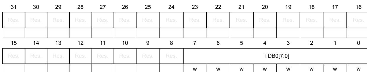
| 31 | 30 | 29 | 28 | 27 | 26 | 25 | 24 | 23 | 22 | 21 | 20 | 19 | 18 | 17 | 16 |
| Res. | Res. | Res. | Res. | Res. | Res. | Res. | Res. | Res. | Res. | Res. | Res. | Res. | Res. | Res. | Res. |
| 15 | 14 | 13 | 12 | 11 | 10 | 9 | 8 | 7 | 6 | 5 | 4 | 3 | 2 | 1 | 0 |
| Res. | Res. | Res. | Res. | Res. | Res. | Res. | Res. | TDB0[7:0] | |||||||
| w | w | w | w | w | w | w | w | ||||||||
Bits 31:8 Reserved, must be kept at reset value.
Bits 7:0 TDB0[7:0] : 8-bit data to transmit on I3C bus.
49.16.7 I3C transmit data word register (I3C_TDWR)
Address offset: 0x01C
Reset value: 0x0000 0000
This register is used to write 32-bit data words to be transmitted over the I3C bus.
This register implements a word-based write access to the transmit FIFO (TX-FIFO), and is used when TXTHRES = 1 in the I3C_CFGR register.
When the I3C acts as controller:
- • When TXDMAEN = 1 and if TXTHRES = 1 in the I3C_CFGR register, programmed I3C and DMA automatically manage by hardware the relevant and successive writes.
- • When TXDMAEN = 0 and if TXTHRES = 1: before a write, the software must wait to be notified that next data word/byte(s) must be written via the TX-FIFO non full flag (TXFNFF = 1 in the I3C_EVR register), or via the corresponding interrupt if enabled. Last transmitted word/byte(s) of a given message to be written in TX-FIFO is also marked with TXLASTF = 1 in the I3C_EVR register.
When the I3C acts as target:
- • When TXDMAEN = 1 and if TXTHRES = 1 and if PRELOAD = 1 in the I3C_TGTDDR register: programmed I3C and DMA automatically manage by hardware the relevant and successive number of writes to the I3C_TDWR register, as per TGTDCNT[15:0]
in the I3C_TGTDR register.
- • When TXDMAEN = 0 and if TXTHRES = 1:
- – when PRELOAD = 1: before a write, the software must wait to be notified that must be written a next data word via the TX-FIFO non full flag (TXFNFF = 1 in the I3C_EVR register) or via the corresponding interrupt, if enabled. Last transmitted word of the initially programmed TGTTDCNT[15:0] in the I3C_TGTTDR register is also marked with TXLASTF = 1 in the I3C_EVR register.
- – when PRELOAD = 0: before a write, the software must wait to be notified that can be written up to two next data words (TX-FIFO size) via the TX-FIFO empty flag (TXFEF = 1 in the I3C_EVR register) or via the corresponding interrupt if enabled. If the software needs to write another data word, it must wait for TX-FIFO to be empty (TXFEF = 1), and then write the next data word to be transmitted before nine SCL clock periods elapse, to avoid a data underrun error flag (ERRF = 1 in the I3C_EVR register and DOVR = 1 in the I3C_SER register).
If the TX-FIFO is empty and the controller/target cannot wait longer a data byte to be transmitted, the software is notified by an error flag ERRF = 1 in the I3C_EVR register and a data underrun flag DOF = 1 in the I3C_SER register (and corresponding interrupt if enabled).
| 31 | 30 | 29 | 28 | 27 | 26 | 25 | 24 | 23 | 22 | 21 | 20 | 19 | 18 | 17 | 16 |
|---|---|---|---|---|---|---|---|---|---|---|---|---|---|---|---|
| TDB3[7:0] | TDB2[7:0] | ||||||||||||||
| w | w | w | w | w | w | w | w | w | w | w | w | w | w | w | w |
| 15 | 14 | 13 | 12 | 11 | 10 | 9 | 8 | 7 | 6 | 5 | 4 | 3 | 2 | 1 | 0 |
| TDB1[7:0] | TDB0[7:0] | ||||||||||||||
| w | w | w | w | w | w | w | w | w | w | w | w | w | w | w | w |
Bits 31:24 TDB3[7:0] : 8-bit transmit data (latest byte on I3C bus).
Bits 23:16 TDB2[7:0] : 8-bit transmit data (next byte after TDB1[7:0] on I3C bus).
Bits 15:8 TDB1[7:0] : 8-bit transmit data (next byte after TDB0[7:0] on I3C bus).
Bits 7:0 TDB0[7:0] : 8-bit transmit data (earliest byte on I3C bus)
49.16.8 I3C IBI payload data register (I3C_IBIDR)
Address offset: 0x020
Reset value: 0x0000 0000
This register is used for the IBI payload data.
When I3C acts as target:
- • if BCR2 = 0 in the I3C_BCR register, this register is useless.
- • if BCR2 = 1, this register must be written by software
- – to be emitted on the I3C bus as the IBI payload data, after that the IBI request (MTYPE[3:0] = 1010 in the I3C_CR register) is acknowledged by the controller; with the IBI data payload size defined by DCNT[15:0] in the I3C_CR register.
- – Maximum (static) payload data size is given by IBIP[2:0] in the I3C_MAXRLR register. it can be 1, 2, 3 or 4 bytes.
- – DCNT[15:0] must be set between 1 (for the mandatory data byte MDB[7:0]) and the maximum IBIP[2:0].
When I3C acts as controller: if IBIACK= 1 in the I3C_DEVRx register, once it acknowledges on the I3C bus the IBI request from the target x:
- • if IBIDEN = 0 (BCR[2] = 0 received from target x) in the I3C_DEVRx register, this register is useless.
- • if IBIDEN = 1 (BCR[2] = 1 received from target x):
- – This register is internally written by hardware from the IBI payload data received on the I3C bus (including the first mandatory data byte MDB[7:0]).
- – When the last byte of the payload is received in I3C_IBIDR (when target drives T-bit = 0), IBIF flag is set (and corresponding interrupt if enabled) in the I3C_EVR register.
- – Then, the software can identify the target x via the received and logged 7-bit address in RADD[6:0] in the I3C_RMR register.
- – The software can read this register and interpret byte(s) according to the number of bytes effectively received and logged in IBIRDCNT[2:0] in the I3C_RMR register.
| 31 | 30 | 29 | 28 | 27 | 26 | 25 | 24 | 23 | 22 | 21 | 20 | 19 | 18 | 17 | 16 |
|---|---|---|---|---|---|---|---|---|---|---|---|---|---|---|---|
| IBIDB3[7:0] | IBIDB2[7:0] | ||||||||||||||
| rw | rw | rw | rw | rw | rw | rw | rw | rw | rw | rw | rw | rw | rw | rw | rw |
| 15 | 14 | 13 | 12 | 11 | 10 | 9 | 8 | 7 | 6 | 5 | 4 | 3 | 2 | 1 | 0 |
| IBIDB1[7:0] | IBIDB0[7:0] | ||||||||||||||
| rw | rw | rw | rw | rw | rw | rw | rw | rw | rw | rw | rw | rw | rw | rw | rw |
Bits 31:24 IBIDB3[7:0] : 8-bit IBI payload data (latest byte on I3C bus).
Bits 23:16 IBIDB2[7:0] : 8-bit IBI payload data (next byte on I3C bus after IBIDB1[7:0]).
Bits 15:8 IBIDB1[7:0] : 8-bit IBI payload data (next byte on I3C bus after IBIDB0[7:0]).
Bits 7:0 IBIDB0[7:0] : 8-bit IBI payload data (earliest byte on I3C bus, MDB[7:0] mandatory data byte).
49.16.9 I3C target transmit configuration register (I3C_TGTTDR)
Address offset: 0x024
Reset value: 0x0000 0000
When I3C acts as target, this register must be used to preload a number of data bytes in the TX-FIFO, so that they are ready to be transmitted on the I3C bus, when they are accepted/acknowledged by the controller, whatever the DMA mode is used or not (independently from TXDMAEN in the I3C_CFGR register).
When I3C acts as target, alternatively, if the number of data bytes to be transmitted is less than or equal to the TX-FIFO size (8 bytes), the software can directly use and write byte(s) into the I3C_TDR register (or I3C_TDWR register, depending upon TXTHRES in the I3C_CFGR register), via polling on the TX-FIFO empty flag (TXFEF = 1 in the I3C_EVR register), or via the corresponding enabled interrupt.
In any case, since an I3C target is unable to stretch/stall the SCL line, the software can identify a TX-FIFO underrun via DOR = 1 in the I3C_EVR register.
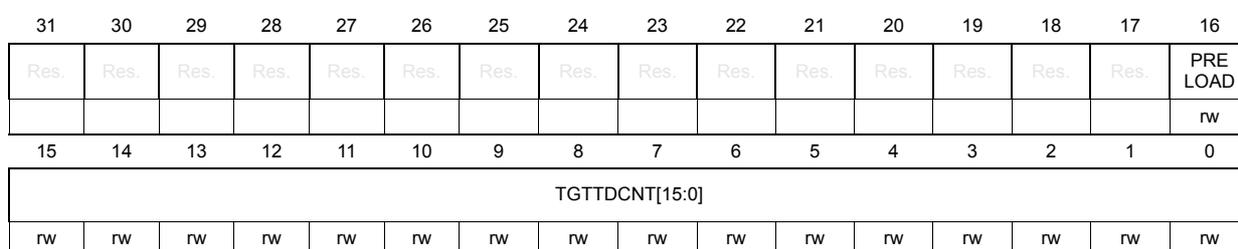
| 31 | 30 | 29 | 28 | 27 | 26 | 25 | 24 | 23 | 22 | 21 | 20 | 19 | 18 | 17 | 16 |
| Res. | Res. | Res. | Res. | Res. | Res. | Res. | Res. | Res. | Res. | Res. | Res. | Res. | Res. | Res. | PRELOAD |
| rw | |||||||||||||||
| 15 | 14 | 13 | 12 | 11 | 10 | 9 | 8 | 7 | 6 | 5 | 4 | 3 | 2 | 1 | 0 |
| TGTTDCNT[15:0] | |||||||||||||||
| rw | rw | rw | rw | rw | rw | rw | rw | rw | rw | rw | rw | rw | rw | rw | rw |
Bits 31:17 Reserved, must be kept at reset value.
Bit 16 PRELOAD : Preload of the TX-FIFO (when I3C is configured as target)
This bit must be written and asserted by software in the same access when is written and defined the number of bytes to preload into the TX-FIFO and to transmit.
This bit is cleared by hardware when all the data bytes to transmit are loaded into the TX-FIFO.
0: no TX-FIFO preload
1: TX-FIFO preload
Bits 15:0 TGTTDCNT[15:0] : Transmit data counter, in bytes (when I3C is configured as target)
This bitfield must be written by software in the same access when is asserted PRELOAD, in order to define the number of bytes to preload and to transmit.
This bitfield is updated by hardware and reports, when read, the remaining number of bytes to be loaded into the TX-FIFO.
49.16.10 I3C status register (I3C_SR)
Address offset: 0x030
Reset value: 0x0000 0000
This register is used to read the status about the exchanged message on the I3C bus:
- • in FIFO mode: when the I3C acts as controller and if S-FIFO is enabled via SMODE = 1 in the I3C_CFGR register:
- – Software is notified via SFNEF = 1 in the I3C_EVR register if there is a status register to be read (and corresponding interrupt if enabled), when not in DMA mode (SDMAEN = 0)
- – In DMA mode (SDMAEN = 1), programmed I3C and DMA automatically manage by hardware the relevant and successive reads.
- – Software is notified via COVR = 1 in the I3C_SER register on an S-FIFO overflow (and ERRF = 1 in the I3C_EVR register and corresponding interrupt if enabled)
- • in register mode: if SMODE = 0 in the I3C_CFGR register
- – Software can use the flags FCF in the I3C_SER register and ERRF = 1 in the I3C_EVR register (and corresponding interrupt if enabled) to read this register
- – This register can be overwritten by hardware on a new message completion, without any notification.
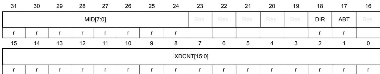
| 31 | 30 | 29 | 28 | 27 | 26 | 25 | 24 | 23 | 22 | 21 | 20 | 19 | 18 | 17 | 16 |
| MID[7:0] | Res. | Res. | Res. | Res. | Res. | DIR | ABT | Res. | |||||||
| r | r | r | r | r | r | r | r | r | r | ||||||
| 15 | 14 | 13 | 12 | 11 | 10 | 9 | 8 | 7 | 6 | 5 | 4 | 3 | 2 | 1 | 0 |
| XDCNT[15:0] | |||||||||||||||
| r | r | r | r | r | r | r | r | r | r | r | r | r | r | r | r |
Bits 31:24 MID[7:0] : Message identifier/counter of a given frame (when the I3C acts as controller)
When I3C acts as controller, this fbitfield identifies the control word message (I3C_CR) to whom the I3C_SR status register refers.
First message of a frame is identified with MID[7:0] = 0.
This bitfield is incremented (by hardware) on the completion of a new message control word (I3C_CR) over I3C bus. This field is reset for every new frame start.
Bits 23:19 Reserved, must be kept at reset value.
Bit 18 DIR : Message direction
Whatever the I3C acts as controller or target, this bit indicates the direction of the related message on the I3C bus
0: write
1: read
Note: ENTDAA CCC is considered as a write command.
Bit 17 ABT : A private read message is ended prematurely by the target (when the I3C acts as controller)
When the I3C acts as controller, this bit indicates if the private read data transmitted by the target early terminates (the target drives T bit low earlier vs. what the controller expects in terms of programmed number of read data bytes DCNT[15:0] in the I3C_CR register).
0: no early completion from the target
1: early completion from the target
Bit 16 Reserved, must be kept at reset value.
Bits 15:0 XDCNT[15:0] : Data counter
Condition: during the dynamic address assignment process (ENTDAA CCC)
- When the I3C acts as controller: number of targets detected on the bus
- When the I3C acts as target: number of transmitted bytes
Condition: for other transfers, during the message
- Whatever the I3C acts as controller or target: number of data bytes read from or transmitted on the I3C bus during the message
49.16.11 I3C status error register (I3C_SER)
Address offset: 0x034
Reset value: 0x0000 0000
This read register is used to get more information about the error when an error is raised by hardware and notified to the software via the error flag ERRF = 1 in the I3C_EVR register (and corresponding interrupt if enabled).
| 31 | 30 | 29 | 28 | 27 | 26 | 25 | 24 | 23 | 22 | 21 | 20 | 19 | 18 | 17 | 16 |
|---|---|---|---|---|---|---|---|---|---|---|---|---|---|---|---|
| Res. | Res. | Res. | Res. | Res. | Res. | Res. | Res. | Res. | Res. | Res. | Res. | Res. | Res. | Res. | Res. |
| 15 | 14 | 13 | 12 | 11 | 10 | 9 | 8 | 7 | 6 | 5 | 4 | 3 | 2 | 1 | 0 |
| Res. | Res. | Res. | Res. | Res. | DERR | DNACK | ANACK | COVR | DOVR | STALL | PERR | CODERR[3:0] | |||
| r | r | r | r | r | r | r | r | r | r | r | |||||
Bits 31:11 Reserved, must be kept at reset value.
Bit 10 DERR : Data error (when the I3C acts as controller)
0: no detected error
1: controller detected a data error during the controller-role hand-off procedure (GETACCCR CCC, formerly known as GETACCMST) when the received target address or/and the parity bit do not match. Active controller keeps controller-role.
Bit 9 DNACK : Data not acknowledged (when the I3C acts as controller)
0: no detected error
1: controller detected that a data byte is not acknowledged by a target, either during:
i) a legacy I2C write transfer
ii) the second trial when sending dynamic address during ENTDAA procedure
Bit 8 ANACK : Address not acknowledged (when the I3C is configured as controller)
0: no detected error
1: controller detected that the static/dynamic address was not acknowledged by a target, either during:
- i) a legacy I2C read/write transfer
- ii) a direct CCC write transfer
- iii) the second trial of a direct CCC read transfer
- iv) a private read/write transfer
Bit 7 COVR : C-FIFO underrun or S-FIFO overrun (when the I3C acts as controller)
0: no detected error
1: controller detected either:
- i) a C-FIFO underrun: control FIFO is empty and a restart must be emitted
- ii) an S-FIFO overrun: S-FIFO is full and a new message ends
Bit 6 DOVR : RX-FIFO overrun or TX-FIFO underrun
0: no detected error
1: whatever controller or target, hardware detected either:
- i) a TX-FIFO underrun: TX-FIFO is empty and a write data byte must be transmitted
- ii) a RX-FIFO overrun: RX-FIFO is full and a new data byte is received
Bit 5 STALL : SCL stall error (when the I3C acts as target)
0: no detected error
1: target detected that SCL was stable for more than 125 µs during an I3C SDR data read (during a direct CCC read, a private read, or an IB)
Bit 4 PERR : Protocol error
0: no detected error
1: whatever controller or target, hardware detected a protocol error, as detailed in CODERR[3:0]
- Bits 3:0 CODERR[3:0] : Protocol error code/type
- 0000: CE0 error (transaction after sending CCC):
controller detected an illegally formatted CCC - 0001: CE1 error (monitoring error):
controller detected that transmitted data on the bus is different from expected - 0010: CE2 error (no response to broadcast address):
controller detected a not acknowledged broadcast address (0b111_1110) - 0011: CE3 error (failed controller-role hand-off):
controller detected the new controller did not drive bus after controller-role hand-off - 1000: TE0 error (invalid broadcast address 0b111_1110 + W):
target detected an invalid broadcast address 0b111_1110 + W - 1001: TE1 error (CCC code):
target detected a parity error on a CCC code via a parity check (vs. T bit) - 1010: TE2 error (write data):
target detected a parity error on a write data via a parity check (vs. T bit) - 1011: TE3 error (assigned address during dynamic address arbitration):
target detected a parity error on the assigned address during dynamic address arbitration via a parity check (vs. PAR bit) - 1100: TE4 error (0b111_1110 + R missing after Sr during dynamic address arbitration):
target detected a 0b111_1110 + R missing after Sr during dynamic address arbitration - 1101: TE5 error (transaction after detecting CCC):
target detected an illegally formatted CCC - 1110: TE6 error (monitoring error):
target detected that transmitted data on the bus is different from expected - others: reserved
- 0000: CE0 error (transaction after sending CCC):
49.16.12 I3C received message register (I3C_RMR)
Address offset: 0x040
Reset value: 0x0000 0000
When the I3C acts as controller, this read register is used to log the received target address, and the IBI received payload data size.
When the I3C acts as target, this read register is used to log the received CCC code
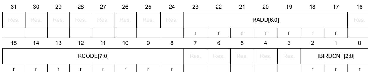
| 31 | 30 | 29 | 28 | 27 | 26 | 25 | 24 | 23 | 22 | 21 | 20 | 19 | 18 | 17 | 16 |
| Res. | Res. | Res. | Res. | Res. | Res. | Res. | Res. | RADD[6:0] | Res. | ||||||
| r | r | r | r | r | r | r | |||||||||
| 15 | 14 | 13 | 12 | 11 | 10 | 9 | 8 | 7 | 6 | 5 | 4 | 3 | 2 | 1 | 0 |
| RCODE[7:0] | Res. | Res. | Res. | Res. | Res. | IBIRDCNT[2:0] | |||||||||
| r | r | r | r | r | r | r | r | r | r | r | |||||
Bits 31:24 Reserved, must be kept at reset value.
Bits 23:17 RADD[6:0] : Received target address (when the I3C is configured as controller)
When the I3C is configured as controller, this field logs the received dynamic address from the target during acknowledged IBI or controller-role request.
Bit 16 Reserved, must be kept at reset value.
Bits 15:8 RCODE[7:0] : Received CCC code (when the I3C is configured as target)
When the I3C is configured as target, this field logs the received CCC code.
Bits 7:3 Reserved, must be kept at reset value.
Bits 2:0 IBIRDCNT[2:0] : IBI received payload data count (when the I3C is configured as controller)
When the I3C is configured as controller, this field logs the number of data bytes effectively received in the I3C_IBIDR register.
49.16.13 I3C event register (I3C_EVR)
Address offset: 0x050
Reset value: 0x0000 0003
This is a read register, used for reporting event flags.
| 31 | 30 | 29 | 28 | 27 | 26 | 25 | 24 | 23 | 22 | 21 | 20 | 19 | 18 | 17 | 16 |
|---|---|---|---|---|---|---|---|---|---|---|---|---|---|---|---|
| GRPF | DEFF | INT UPDF | AS UPDF | RSTF | MRL UPDF | MWL UPDF | DA UPDF | STAF | GETF | WKPF | Res. | HJF | CR UPDF | CRF | IBI ENDF |
| r | r | r | r | r | r | r | r | r | r | r | r | r | r | r |
| 15 | 14 | 13 | 12 | 11 | 10 | 9 | 8 | 7 | 6 | 5 | 4 | 3 | 2 | 1 | 0 |
|---|---|---|---|---|---|---|---|---|---|---|---|---|---|---|---|
| IBIF | Res. | Res. | Res. | ERRF | RXTGT ENDF | FCF | Res. | RX LASTF | TX LASTF | RX FNEF | TX FNFF | SFNEF | CFNFF | TXFEF | CFEF |
| r | r | r | r | r | r | r | r | r | r | r | r |
Bit 31 GRPF : Group addressing flag (when the I3C acts as target)
When the I3C acts as target (and is typically controller-capable), this flag is asserted by hardware to indicate that the broadcast DEFGPRPA CCC (define list of group addresses) has been received. Then, software can store the received data for when getting controller role. The flag is cleared when software writes 1 into the corresponding CGRPF bit in the I3C_CR register.
Bit 30 DEFF : DEFTGTS flag (when the I3C acts as target)
When the I3C acts as target (and is typically controller capable), this flag is asserted by hardware to indicate that the broadcast DEFTGTS CCC (define list of targets) has been received. Then, software can store the received data for when getting the controller role. The flag is cleared when software writes 1 into the corresponding CDEFF bit in the I3C_CEVR register.
Bit 29 INTUPDF : Interrupt/controller-role/hot-join update flag (when the I3C acts as target)
When the I3C acts as target, this flag is asserted by hardware to indicate that the direct or broadcast ENEC/DISEC CCC (enable/disable target events) has been received, where a target event is either an interrupt/IBI request, a controller-role request, or an hot-join request. Then, software must read respectively IBIEN, CREN, or HJEN in the I3C_DEVR0 register. The flag is cleared when software writes 1 into the corresponding CINTUPDF bit in the I3C_CEVR register.
Bit 28 ASUPDF : Activity state update flag (when the I3C acts as target)
When the I3C acts as target, this flag is asserted by hardware to indicate that the direct or broadcast ENTASx CCC (with x = 0...3) has been received. Then, software must read AS[1:0] in the I3C_DEVR0 register. The flag is cleared when software writes 1 into the corresponding CASUPDF bit in the I3C_CEVR register.
Bit 27 RSTF: Reset pattern flag (when the I3C acts as target)When I3C acts as target, this flag is asserted by hardware to indicate that a reset pattern has been detected (14 SDA transitions while SCL is low, followed by repeated start, then stop).
Then, when not in Stop mode, software must read RSTACT[1:0] and RSTVAL in the I3C_DEVR0 register, to know the required reset level.
- – If RSTVAL = 1: when the RSTF is asserted (and/or the corresponding interrupt if enabled), RSTACT[1:0] in the I3C_DEVR0 register dictates the reset action to be performed by the software, if any.
- – If RSTVAL = 0: when the RSTF is asserted (and/or the corresponding interrupt if enabled), the software must issue an I3C reset after a first detected reset pattern, and a system reset on the second one.
When in Stop mode, the corresponding interrupt can be used to wake up the device.
The flag is cleared when software writes 1 into the corresponding CRSTF bit in the I3C_CEVR register.
Bit 26 MRLUPDF: Maximum read length update flag (when the I3C acts as target)When the I3C acts as target, this flag is asserted by hardware to indicate that a direct SETMRL CCC (set max read length) has been received. Then, software must read MRL[15:0] in the I3C_MAXRLR register to get the maximum read length value.
The flag is cleared when software writes 1 into the corresponding CMRLUPDF bit in the I3C_CEVR register.
Bit 25 MWLUPDF: Maximum write length update flag (when the I3C acts as target)When the I3C acts as target, this flag is asserted by hardware to indicate that a direct SETMWL CCC (set max write length) has been received. Then, software must read MWL[15:0] in the I3C_MAXRLR register to get the maximum write length value.
The flag is cleared when software writes 1 into the corresponding CMWLUPDF bit in the I3C_CEVR register.
Bit 24 DAUPDF: Dynamic address update flag (when the I3C acts as target)When the I3C acts as target, this flag is asserted by hardware to indicate that a dynamic address update has been received via any of the broadcast ENTDAA, RSTDAA and direct SETNEWDA CCC. Then, software must read DA[6:0] and DAVAL in the I3C_DEVR0 register to get the dynamic address update.
The flag is cleared when software writes 1 into the corresponding CDAUPDF bit in the I3C_CEVR register.
Bit 23 STAF: Get status flag (when the I3C acts as target)When the I3C acts as target, this flag is asserted by hardware to indicate that a direct GETSTATUS CCC of format 1 (without defining byte or with defining byte TGTSTAT) has been received.
The flag is cleared when software writes 1 into the corresponding CSTAF bit in the I3C_CEVR register.
Bit 22 GETF: Get flag (when the I3C acts as target)When the I3C acts as target, this flag is asserted by hardware to indicate that any direct CCC of get type (GET*** CCC) except the GETSTATUS of format 1 (but including GETSTATUS of format 2) has been received.
The flag is cleared when software writes 1 into the corresponding CGETF bit in the I3C_CEVR register.
Bit 21 WKPF : Wake-up/missed start flag (when the I3C acts as target)
When the I3C acts as target, this flag is asserted by hardware to indicate that a start has been detected (an SDA falling edge followed by an SCL falling edge) but on the next SCL falling edge, the I3C kernel clock is (still) gated. Thus an I3C bus transaction may have been lost by the target.
The corresponding interrupt can be used to wake up the device from a low power (Sleep or Stop) mode.
The flag is cleared when software writes 1 into the corresponding CWKPF bit in the I3C_CEVR register.
Bit 20 Reserved, must be kept at reset value.
Bit 19 HJF : Hot-join flag (when the I3C acts as controller)
When the I3C acts as controller, this flag is asserted by hardware to indicate that an hot join request has been received.
The flag is cleared when software writes 1 into the corresponding CHJF bit in the I3C_CEVR register.
Bit 18 CRUPDF : Controller-role update flag (when the I3C acts as target)
When the I3C acts as target, this flag is asserted by hardware to indicate that it has now gained the controller role after the completed controller-role hand-off procedure.
The flag is cleared when software writes 1 into the corresponding CCRUPDF bit in the I3C_CEVR register.
Bit 17 CRF : Controller-role request flag (when the I3C acts as controller)
When the I3C acts as controller, this flag is asserted by hardware to indicate that a controller-role request has been acknowledged and completed (by hardware). The software must then issue a GETACCCR CCC (get accept controller role) for the controller-role hand-off procedure.
The flag is cleared when software writes 1 into the corresponding CCRF bit in the I3C_CEVR register.
Bit 16 IBIENDF : IBI end flag (when the I3C acts as target)
When the I3C acts as target, this flag is asserted by hardware to indicate that an IBI transfer has been received and completed (IBI acknowledged and IBI data bytes read by controller if any).
The flag is cleared when software writes 1 into the corresponding CIBIENDF bit in the I3C_CEVR register.
Bit 15 IBIF : IBI flag (when the I3C acts as controller)
When the I3C acts as controller, this flag is asserted by hardware to indicate that an IBI request has been received.
The flag is cleared when software writes 1 into the corresponding CIBIF bit in the I3C_CEVR register.
Bits 14:12 Reserved, must be kept at reset value.
Bit 11 ERRF : Flag (whatever the I3C acts as controller/target)
This flag is asserted by hardware to indicate that an error occurred. Then, software must read I3C_SER to get the error type.
The flag is cleared when software writes 1 into the corresponding CERRF bit in the I3C_CEVR register.
Bit 10 RXTGTENDF : Target-initiated read end flag (when the I3C acts as controller)
When the I3C acts as controller, and only if the S-FIFO is disabled (SMODE = 0 in the I3C_CFGR register), this flag is asserted by hardware to indicate that the target has prematurely ended a read transfer. Then, software must read the status register I3C_SR to check information related to the last message and get the number of received data bytes on the prematurely read transfer (XDCNT in the I3C_SR register).
The flag is cleared when software writes 1 into the corresponding CRXTGTENDF bit in the I3C_CEVR register.
Bit 9 FCF : Frame complete flag (whatever the I3C acts as controller/target)
When the I3C acts as controller, this flag is asserted by hardware to indicate that a frame has been (normally) completed on the I3C bus, for example, when a stop is issued.
When the I3C acts as target, this flag is asserted by hardware to indicate that a message addressed to/by this target has been (normally) completed on the I3C bus, for example, when a next stop or repeated start is then issued by the controller.
The flag is cleared when software writes 1 into the corresponding CFCF bit in the I3C_CEVR register.
Bit 8 Reserved, must be kept at reset value.
Bit 7 RXLASTF : Last read data byte/word flag (when the I3C acts as controller)
When the I3C acts as controller, this flag is asserted by hardware to indicate that the last data byte/word (depending upon RXTHRES in the I3C_CFGR register) of a message must be read from the RX-FIFO. The flag is de-asserted by hardware when the last data byte/word of a message is read.
Bit 6 TXLASTF : Last written data byte/word flag (whatever the I3C acts as controller/target)
This flag is asserted by hardware to indicate that the last data byte/word (depending upon TXTHRES in the I3C_CFGR register) of a message must be written to the TX-FIFO. The flag is de-asserted by hardware when the last data byte/word of a message is written.
Bit 5 RXFNEF : RX-FIFO not empty flag (whatever the I3C acts as controller/target)
This flag is asserted/de-asserted by hardware to indicate that a data byte must/must not be read from the RX-FIFO.
Note: The software must wait for RXFNEF = 1 (by polling or via the enabled interrupt) before reading from RX-FIFO (reading from I3C_RDR or I3C_RDWR, depending upon RXTHRES).
Bit 4 TXFNFF : TX-FIFO not full flag (whatever the I3C acts as controller/target)
This flag is asserted/de-asserted by hardware to indicate that a data byte/word must/must not be written to the TX-FIFO.
Note: The software must wait for TXFNFF = 1 (by polling or via the enabled interrupt) before writing to TX-FIFO (writing to I3C_TDR or I3C_TDWR, depending upon TXTHRES).
Note: When the I3C acts as target, if the software intends to use the TXFNFF flag for writing into I3C_TDR/I3C_TDWR, it must have configured and set the TX-FIFO preload (write PRELOAD in the I3C_TGTTDR register).
Bit 3 SFNEF : S-FIFO not empty flag (when the I3C acts as controller)
When the I3C acts as controller, if the S-FIFO is enabled (SMODE = 1 in the I3C_CFGR register), this flag is asserted by hardware to indicate that a status word must be read from the S-FIFO. The flag is de-asserted by hardware to indicate that a status word is not to be read from the S-FIFO.
Bit 2 CFNFF : C-FIFO not full flag (when the I3C acts as controller)
When the I3C acts as controller, this flag is asserted by hardware to indicate that a control word must be written to the C-FIFO. The flag is de-asserted by hardware to indicate that a control word is not to be written to the C-FIFO.
Note: The software must wait for CFNFF = 1 (by polling or via the enabled interrupt) before writing to C-FIFO (writing to I3C_CR).
Bit 1 TXFEF : TX-FIFO empty flag (whatever the I3C acts as controller/target)
This flag is asserted by hardware to indicate that the TX-FIFO is empty.
This flag is de-asserted by hardware to indicate that the TX-FIFO is not empty.
Bit 0 CFEF : C-FIFO empty flag (whatever the I3C acts as controller)
This flag is asserted by hardware to indicate that the C-FIFO is empty when controller, and that the I3C_CR register contains no control word (none IBI/CR/HJ request) when target.
This flag is de-asserted by hardware to indicate that the C-FIFO is not empty when controller, and that the I3C_CR register contains one control word (a pending IBI/CR/HJ request) when target.
Note: When the I3C acts as controller, if the C-FIFO and TX-FIFO preload is configured (TMODE = 1 in the I3C_CFGR register), the software must wait for TXFEF = 1 and CFEF = 1 before starting a new frame transfer.
49.16.14 I3C interrupt enable register (I3C_IER)
Address offset: 0x054
Reset value: 0x0000 0000
This register is used to enable/disable, at bit level, an interrupt, for each of the following event/flag.
| 31 | 30 | 29 | 28 | 27 | 26 | 25 | 24 | 23 | 22 | 21 | 20 | 19 | 18 | 17 | 16 |
|---|---|---|---|---|---|---|---|---|---|---|---|---|---|---|---|
| GRPIE | DEFIE | INTUPDIE | ASUPDIE | RSTIE | MRLUPDIE | MWLUPDIE | DAUPDIE | STAIE | GETIE | WKPIE | Res. | HJIE | CRUPDIE | CRIE | IBIENDIE |
| r | r | r | r | r | r | r | r | r | r | r | r | r | r | r |
| 15 | 14 | 13 | 12 | 11 | 10 | 9 | 8 | 7 | 6 | 5 | 4 | 3 | 2 | 1 | 0 |
|---|---|---|---|---|---|---|---|---|---|---|---|---|---|---|---|
| IBIIE | Res. | Res. | Res. | ERRIE | RXTGTENDIE | FCIE | Res. | Res. | Res. | RXFNEIE | TXFNEIE | SFNEIE | CFNFIE | Res. | Res. |
| r | r | r | r | r | r | r | r |
Bit 31 GRPIE : DEFGRA CCC interrupt enable (when the I3C acts as target)
0: interrupt disabled
1: interrupt enabled
Bit 30 DEFIE : DEFTGTS CCC interrupt enable (when the I3C acts as target)
0: interrupt disabled
1: interrupt enabled
Bit 29 INTUPDIE : ENEC/DISEC CCC interrupt enable (when the I3C acts as target)
0: interrupt disabled
1: interrupt enabled
- Bit 28
ASUPDIE
: ENTASx CCC interrupt enable (when the I3C acts as target)
0: interrupt disabled
1: interrupt enabled - Bit 27
RSTIE
: reset pattern interrupt enable (when the I3C acts as target)
0: interrupt disabled
1: interrupt enabled - Bit 26
MRLUPDIE
: SETMRL CCC interrupt enable (when the I3C acts as target)
0: interrupt disabled
1: interrupt enabled - Bit 25
MWLUPDIE
: SETMWL CCC interrupt enable (when the I3C acts as target)
0: interrupt disabled
1: interrupt enabled - Bit 24
DAUPDIE
: ENTDAARSTDAA/SETNEWDA CCC interrupt enable (when the I3C acts as target)
0: interrupt disabled
1: interrupt enabled - Bit 23
STAIE
: format 1 GETSTATUS CCC interrupt enable (when the I3C acts as target)
0: interrupt disabled
1: interrupt enabled - Bit 22
GETIE
: GETxxx CCC interrupt enable (except GETSTATUS of format 1) (when the I3C acts as target)
0: interrupt disabled
1: interrupt enabled - Bit 21
WKPIE
: Wake-up interrupt enable (when the I3C acts as target)
0: interrupt disabled
1: interrupt enabled - Bit 20 Reserved, must be kept at reset value.
- Bit 19
HJIE
: Hot-join interrupt enable (when the I3C acts as controller)
0: interrupt disabled
1: interrupt enabled - Bit 18
CRUPDIE
: Controller-role update interrupt enable (when the I3C acts as target)
0: interrupt disabled
1: interrupt enabled - Bit 17
CRIE
: Controller-role request interrupt enable (when the I3C acts as controller)
0: interrupt disabled
1: interrupt enabled - Bit 16
IBIENDIE
: IBI end interrupt enable (when the I3C acts as target)
0: interrupt disabled
1: interrupt enabled - Bit 15
IBIIE
: IBI request interrupt enable (when the I3C acts as controller)
0: interrupt disabled
1: interrupt enabled - Bits 14:12 Reserved, must be kept at reset value.
- Bit 11
ERRIE
: error interrupt enable (whatever the I3C acts as controller/target)
0: interrupt disabled
1: interrupt enabled - Bit 10
RXTGTENDIE
: target-initiated read end interrupt enable (when the I3C acts as controller)
0: interrupt disabled
1: interrupt enabled - Bit 9
FCIE
: frame complete interrupt enable (whatever the I3C acts as controller/target)
0: interrupt disabled
1: interrupt enabled - Bits 8:6 Reserved, must be kept at reset value.
- Bit 5
RXFNEIE
: RX-FIFO not empty interrupt enable (whatever the I3C acts as controller/target)
0: interrupt disabled
1: interrupt enabled - Bit 4
TXFNFIE
: TX-FIFO not full interrupt enable (whatever the I3C acts as controller/target)
0: interrupt disabled
1: interrupt enabled - Bit 3
SFNEIE
: S-FIFO not empty interrupt enable when the I3C acts as controller
0: interrupt disabled
1: interrupt enabled - Bit 2
CFNFIE
: C-FIFO not full interrupt enable when the I3C acts as controller
0: interrupt disabled
1: interrupt enabled - Bits 1:0 Reserved, must be kept at reset value.
49.16.15 I3C clear event register (I3C_CEVR)
Address offset: 0x058
Reset value: 0x0000 0000
This write register is used to clear individually, at bit level, the corresponding event flag of the I3C_EVR register.
| 31 | 30 | 29 | 28 | 27 | 26 | 25 | 24 | 23 | 22 | 21 | 20 | 19 | 18 | 17 | 16 |
|---|---|---|---|---|---|---|---|---|---|---|---|---|---|---|---|
| CGRPF | CDEFF | CINTUPDF | CASUPDF | CRSTF | CMRLUPDF | CMWLUPDF | CDAUPDF | CSTAF | CGETF | CWKPF | Res. | CHJF | CCRUPDF | CCRF | CIBENDF |
| w | w | w | w | w | w | w | w | w | w | w | w | w | w | w | |
| 15 | 14 | 13 | 12 | 11 | 10 | 9 | 8 | 7 | 6 | 5 | 4 | 3 | 2 | 1 | 0 |
| CIBIF | Res. | Res. | Res. | CERRF | CRXTGTENDF | CFCF | Res. | Res. | Res. | Res. | Res. | Res. | Res. | Res. | Res. |
| w | w | w | w |
- Bit 31
CGRPF
: Clear DEFGRPA CCC flag (when the I3C acts as target)
0: no effect
1: clear GRPF
- Bit 30
CDEFF
: Clear DEFTGTS CCC flag (when the I3C acts as target)
0: no effect
1: clear DEFF - Bit 29
CINTUPDF
: Clear ENEC/DISEC CCC flag (when the I3C acts as target)
0: no effect
1: clear CINTUPDF - Bit 28
CASUPDF
: Clear ENTASx CCC flag (when the I3C acts as target)
0: no effect
1: clear ASUPDF - Bit 27
CRSTF
: Clear reset pattern flag (when the I3C acts as target)
0: no effect
1: clear RSTF - Bit 26
CMRLUPDF
: Clear SETMRL CCC flag (when the I3C acts as target)
0: no effect
1: clear MRLUPDF - Bit 25
CMWLUPDF
: Clear SETMWL CCC flag (when the I3C acts as target)
0: no effect
1: clear MWLUPDF - Bit 24
CDAUPDF
: Clear ENTDAAR/STDAA/SETNEWDA CCC flag (when the I3C acts as target)
0: no effect
1: clear DAUPDF - Bit 23
CSTAF
: Clear format 1 GETSTATUS CCC flag (when the I3C acts as target)
0: no effect
1: clear STAF - Bit 22
CGETF
: Clear GETxxx CCC flag (except GETSTATUS of format 1) (when the I3C acts as target)
0: no effect
1: clear GETF - Bit 21
CWKPF
: Clear wake-up flag (when the I3C acts as target)
0: no effect
1: clear WKPF - Bit 20 Reserved, must be kept at reset value.
- Bit 19
CHJF
: Clear hot-join flag (when the I3C acts as controller)
0: no effect
1: clear HJF - Bit 18
CCRUPDF
: Clear controller-role update flag (when the I3C acts as target)
0: no effect
1: clear CRUPDF - Bit 17
CCRF
: Clear controller-role request flag (when the I3C acts as controller)
0: no effect
1: clear CRF - Bit 16
CIBIENDF
: Clear IBI end flag (when the I3C acts as target)
0: no effect
1: clear IBIENDF
Bit 15 CIBIF : Clear IBI request flag (when the I3C acts as controller)
0: no effect
1: clear IBIF
Bits 14:12 Reserved, must be kept at reset value.
Bit 11 CERRF : Clear error flag (whatever the I3C acts as controller/target)
0: no effect
1: clear ERRF
Bit 10 CRXTGTENDF : Clear target-initiated read end flag (when the I3C acts as controller)
0: no effect
1: clear RXTGTENDF
Bit 9 CFCF : Clear frame complete flag (whatever the I3C acts as controller/target)
0: no effect
1: clear FCF
Bits 8:0 Reserved, must be kept at reset value.
49.16.16 I3C own device characteristics register (I3C_DEVR0)
Address offset: 0x060
Reset value: 0x0000 0000
When the I3C peripheral acts as target, this register is used to write or read its own device characteristics.
When the I3C peripheral acts as controller, the field DA[6:0] is used to write and store its own dynamic address.
| 31 | 30 | 29 | 28 | 27 | 26 | 25 | 24 | 23 | 22 | 21 | 20 | 19 | 18 | 17 | 16 |
|---|---|---|---|---|---|---|---|---|---|---|---|---|---|---|---|
| Res. | Res. | Res. | Res. | Res. | Res. | Res. | RSTVAL | RSTACT[1:0] | AS[1:0] | HJEN | Res. | CREN | IBIEN | ||
| r | r | r | r/w | r/w | r/w | ||||||||||
| 15 | 14 | 13 | 12 | 11 | 10 | 9 | 8 | 7 | 6 | 5 | 4 | 3 | 2 | 1 | 0 |
| Res. | Res. | Res. | Res. | Res. | Res. | Res. | Res. | DA[6:0] | DAVAL | ||||||
| r/w | r/w | r/w | r/w | r/w | r/w | r/w | r/w | ||||||||
Bits 31:25 Reserved, must be kept at reset value.
Bit 24 RSTVAL : Reset action is valid (when the I3C acts as target)
This bit is asserted by hardware to indicate that the RSTACT[1:0] field has been updated on the reception of a broadcast or direct write RSTACT CCC (target reset action) and is valid.
This bit is cleared by hardware when the target receives a frame start.
When the device is not in Stop mode:
- – If RSTVAL = 1: when RSTF in the I3C_EVR register is asserted (and/or the corresponding interrupt if enabled), RSTACT[1:0] in the I3C_DEVR0 register dictates the reset action to be performed by the software, if any.
- – If RSTVAL = 0: when RSTF is asserted (and/or the corresponding interrupt if enabled), the software must issue an I3C reset after a first detected reset pattern, and a system reset on the second one.
When in Stop mode, the corresponding interrupt can be used to wake up the device.
Bits 23:22 RSTACT[1:0] : Reset action/level on received reset pattern (when the I3C acts as target)
This read field is used by hardware on the reception of a direct read RSTACT CCC in order to return the corresponding data byte on the I3C bus.
This read field is updated by hardware on the reception of a broadcast or direct write RSTACT CCC (target reset action).
Only the defining bytes 0x00, 0x01 and 0x02 are mapped, and RSTACT[1:0] = Defining Byte[1:0].
00: no reset action
01: first level of reset: the application software must either:
- partially reset the I3C peripheral, by a write and clear of the enable bit of the I3C configuration register (write EN = 0). This resets the I3C bus interface and the I3C kernel sub-parts, without modifying the content of the I3C APB registers (except the EN bit).
- fully reset the I3C peripheral, including all its registers, via a write and set of the I3C reset control bit of the RCC (reset and clock controller) register.
10: second level of reset: the application software must issue a warm reset, also known as a system reset:
- – the software writes and sets the SYSRESETREQ control bit of the AIRCR register, when the device is controlled by a Cortex ® -M.
11: no reset action
Bits 21:20 AS[1:0] : Activity state (when the I3C acts as target)
This read field is updated by hardware on the reception of a ENTASx CCC (enter activity state, with x = 0-3):
00: activity state 0
01: activity state 1
10: activity state 2
11: activity state 3
Bit 19 HJEN : Hot-join request enable (when the I3C acts as target)
This bit is initially written by software when EN = 0, and is updated by hardware on the reception of DISEC CCC with DISHJ= 1 (cleared) and the reception of ENEC CCC with ENHJ= 1 (set). This bit can only be written by software when EN = 0 in the I3C_CFGR register.
0: hot-join request disabled
1: hot-join request enabled
Bit 18 Reserved, must be kept at reset value.
Bit 17 CREN : Controller-role request enable (when the I3C acts as target)
This bit is initially written by software when EN = 0, and is updated by hardware on the reception of DISEC CCC with DISCR = 1 (cleared) and the reception of ENEC CCC with ENCR = 1 (set). This bit can only be written by software when EN = 0 in the I3C_CFGR register.
0: controller-role request disabled
1: controller-role request enabled
Bit 16 IBIEN : IBI request enable (when the I3C acts as target)
This bit is initially written by software when EN = 0, and is updated by hardware on the reception of DISEC CCC with DISINT = 1 (cleared) and the reception of ENEC CCC with ENINT = 1 (set). This bit can only be written by software when EN = 0 in the I3C_CFGR register.
0: IBI request disabled
1: IBI request enabled
Bits 15:8 Reserved, must be kept at reset value.
Bits 7:1 DA[6:0] : 7-bit dynamic address
When the I3C acts as controller, this field can be written by software, for defining its own dynamic address.
When the I3C acts as target, this field is updated by hardware on the reception of either the broadcast ENTDAACCC or the direct SETNEWDAACCC.
Bit 0 DAVAL : Dynamic address is valid (when the I3C acts as target)
When the I3C acts as controller, this bit can be written by software, for validating its own dynamic address, for example before a controller-role hand-off.
When the I3C acts as target, this bit is asserted by hardware on the acknowledge of the broadcast ENTDAACCC or the direct SETNEWDAACCC, and this field is cleared by hardware on the acknowledge of the broadcast RSTDAACCC.
49.16.17 I3C device x characteristics register (I3C_DEVRx)
Address offset: 0x060 + 0x4 * x, (x = 1 to 4)
Reset value: 0x0000 0000
When the I3C peripheral acts as controller, this register is used to define and store some characteristics of a device target x with their related management from the controller, to communicate accordingly with any of this target x over the I3C bus. Then, the hardware can autonomously identify and acknowledge an allowed IBI or/and controller-role request from a target x, receive the expected IBI payload data if any, and notify the software via the corresponding flag IBIF/CRF (and the corresponding interrupt if enabled) in the I3C_EVR register.
| 31 | 30 | 29 | 28 | 27 | 26 | 25 | 24 | 23 | 22 | 21 | 20 | 19 | 18 | 17 | 16 |
|---|---|---|---|---|---|---|---|---|---|---|---|---|---|---|---|
| DIS | Res. | Res. | Res. | Res. | Res. | Res. | Res. | Res. | Res. | Res. | Res. | SUSP | IBIDEN | CRACK | IBIACK |
| r | rw | rw | rw | rw | |||||||||||
| 15 | 14 | 13 | 12 | 11 | 10 | 9 | 8 | 7 | 6 | 5 | 4 | 3 | 2 | 1 | 0 |
| Res. | Res. | Res. | Res. | Res. | Res. | Res. | Res. | DA[6:0] | Res. | ||||||
| rw | rw | rw | rw | rw | rw | rw | |||||||||
Bit 31 DIS : Disables writes to DA[6:0] (when the I3C acts as controller)
When the I3C acts as controller, once the software sets IBIACK= 1 or CRACK= 1, this read bit is set by hardware (DIS= 1) to lock the configured DA[6:0] and IBIDEN values.
Then, to be able to modify DA[6:0], IBIDEN or SUSP, the software must wait for DIS to be de-asserted by hardware (polling on DIS= 0) before modifying these three assigned values to the target x. Indeed, the target can request an IBI or a controller-role while the controller intends to modify DA[6:0], IBIDEN or SUSP.
0: write to DA[7:0] and to IBIDEN in the I3C_DEVRx register is allowed
1: write to DA[7:0] and to IBIDEN is disabled/locked
Bits 30:20 Reserved, must be kept at reset value.
Bit 19 SUSP : Suspend/stop I3C transfer on received IBI (when the I3C acts as controller)
When the I3C acts as controller, this bit can be used to receive an IBI from target x with pending read notification feature (received MDB[7:5] = 3'b101).
If this bit is set, when an IBI is received and completed (IBIF = 1 in the I3C_EVR register), a stop is emitted on the I3C bus and both C-FIFO and TX-FIFO are automatically flushed by hardware. The controller execution flow is stopped, even if a next control message is programmed. When the IBI is completed, the controller software can issue a new control word, such as a private read, to the target device that initiated the IBI request.
0: C-FIFO and TX-FIFO are not flushed after an IBI request from target x is acknowledged and completed, and depending on the presence or absence of a next control word, a repeated start or a stop is emitted
1: I3C transfer is stopped and both C-FIFO and TX-FIFO are flushed after receiving an IBI request from target x
Bit 18 IBIDEN : IBI data enable (when the I3C acts as controller)
When the I3C acts as controller, this bit must be written by software to store the BCR[2] bit as received from the target x during broadcast ENTDAA or direct GETBCR CCC via the received I3C_RDR.
Writing to this field has no impact when the DIS = 1 in the I3C_DEVRx register.
0: no data byte follows the acknowledged IBI from target x
1: the mandatory data byte MDB[7:0] follows the acknowledged IBI from target x
Bit 17 CRACK : Controller-role request acknowledge (when the I3C acts as controller)
When the I3C acts as controller, this bit is written by software to define the acknowledge policy to be applied on the I3C bus on the reception of a controller-role request from target x:
0: a controller-role request from target x must be NACK-ed
After the NACK, the message continues as initially programmed (the target is aware of the NACK and can emit another controller-role request later on)
1: a controller-role request (with 7-bit dynamic address DA[6:0]) from target x must be ACKed
- The field DIS is asserted by hardware to protect DA[6:0] from being modified by software meanwhile the hardware can store internally the current DA[6:0] into the kernel clock domain.
- After the ACK, the message continues as initially programmed. The software is notified by the controller-role request flag (CRF = 1 in the I3C_EVR register) and/or the corresponding interrupt if enabled; For effectively granting the controller-role to the requesting secondary controller, software must issue a GETACCCR (formerly known as GETACCMST), followed by a stop.
- Independently of CRACK configuration for this or other devices, further controller-role request(s) are NACK-ed until controller-role request flag (CRF) and IBI flag (IBIF) in the I3C_EVR register are both cleared.
Bit 16 IBIACK : IBI request acknowledge (when the I3C acts as controller)
When the I3C acts as controller, this bit is written by software to define the acknowledge policy to be applied on the I3C bus on the reception of an IBI request from target x:
0: an IBI request from target x must be NACK-ed
- - After the NACK, the message continues as initially programmed (the target is aware of the NACK and can emit another IBI request later on)
1: an IBI request (with 7-bit dynamic address DA[6:0]) from target x must be ACKed
- - The field DIS is asserted by hardware to protect DA[6:0] from being modified by software meanwhile the hardware can store internally the current DA[6:0] into the kernel clock domain.
- - After the ACK, the controller logs the IBI payload data, if any, depending on I3C_DEVRx.IBIDEN.
- - The software is notified by the IBI flag (IBIF = 1) and/or the corresponding interrupt if enabled;
- - Independently from IBIACK configuration for this or other devices, further IBI request(s) are NACK-ed until IBI request flag (IBIF) and controller-role request flag (CRF) are both cleared.
Bits 15:8 Reserved, must be kept at reset value.
Bits 7:1 DA[6:0] : Assigned I3C dynamic address to target x (when the I3C acts as controller)
When the I3C acts as controller, this field must be written by software to store the 7-bit dynamic address that the controller sends via a broadcast ENTDAA or a direct SETNEWDA CCC acknowledged by the target x.
Writing to this field has no impact when the read field DIS = 1 in the I3C_DEVRx register.
Bit 0 Reserved, must be kept at reset value.
49.16.18 I3C maximum read length register (I3C_MAXRLR)
Address offset: 0x090
Reset value: 0x0000 0000
When the I3C acts as target, this register is used to set or get the maximum read length value exchanged with the controller during respectively GETMRL or SETMRL CCC. This register is also used to set the IBI data payload size.
This register can be written by the software when EN = 0 in the I3C_CFGR register.
When receiving a private read message, the target ends the data transmission (by driving T-bit = 0) when the count of transmitted data reaches MRL[15:0] in the I3C_MAXRLR register.
| 31 | 30 | 29 | 28 | 27 | 26 | 25 | 24 | 23 | 22 | 21 | 20 | 19 | 18 | 17 | 16 |
|---|---|---|---|---|---|---|---|---|---|---|---|---|---|---|---|
| Res. | Res. | Res. | Res. | Res. | Res. | Res. | Res. | Res. | Res. | Res. | Res. | Res. | IBIP[2:0] | ||
| rw | rw | rw | |||||||||||||
| 15 | 14 | 13 | 12 | 11 | 10 | 9 | 8 | 7 | 6 | 5 | 4 | 3 | 2 | 1 | 0 |
| MRL[15:0] | |||||||||||||||
| rw | rw | rw | rw | rw | rw | rw | rw | rw | rw | rw | rw | rw | rw | rw | rw |
Bits 31:19 Reserved, must be kept at reset value.
Bits 18:16 IBIP[2:0] : IBI payload data maximum size, in bytes (when I3C acts as target)
This field is initially written by software when EN = 0 to set the maximum number of data bytes to be sent to the controller after an IBI request has been acknowledged. This field can be updated by hardware on the reception of SETMRL command (which potentially also updated IBIP[2:0]).
Software is notified of an MRL update by MRLUPF in the I3C_EVR register and the corresponding interrupt, if enabled.
000: null payload data size (only allowed when BCR2 = 0 in the I3C_BCR register)
001: 1 byte (mandatory data byte MDB[7:0])
010: 2 bytes (including first MDB[7:0])
011: 3 bytes (including first MDB[7:0])
100: 4 bytes (including first MDB[7:0])
others: same as 100
Bits 15:0 MRL[15:0] : Maximum data read length (when I3C acts as target)
This field is initially written by software when EN = 0 and updated by hardware on the reception of SETMRL command (with potentially also updated IBIP[2:0]).
Software is notified of an MRL update by MRLUPF and the corresponding interrupt, if enabled.
This field is used by hardware to return the value on the I3C bus when the target receives a GETMRL CCC.
49.16.19 I3C maximum write length register (I3C_MAXWLR)
Address offset: 0x094
Reset value: 0x0000 0000
When the I3C acts as target, this register is used to set or get the maximum write length value exchanged with the controller during respectively GETMWL or SETMWL CCC.
This register can be written by the software when EN = 0 in the I3C_CFGR register.
On receiving a private write message, the target stops the data reception (extra received data are not written into RX-FIFO) when the count of received data reaches MWL[15:0] in the I3C_MAXWLR register.
| 31 | 30 | 29 | 28 | 27 | 26 | 25 | 24 | 23 | 22 | 21 | 20 | 19 | 18 | 17 | 16 |
|---|---|---|---|---|---|---|---|---|---|---|---|---|---|---|---|
| Res. | Res. | Res. | Res. | Res. | Res. | Res. | Res. | Res. | Res. | Res. | Res. | Res. | Res. | Res. | Res. |
| 15 | 14 | 13 | 12 | 11 | 10 | 9 | 8 | 7 | 6 | 5 | 4 | 3 | 2 | 1 | 0 |
| MWL[15:0] | |||||||||||||||
| rw | rw | rw | rw | rw | rw | rw | rw | rw | rw | rw | rw | rw | rw | rw | rw |
Bits 31:16 Reserved, must be kept at reset value.
Bits 15:0 MWL[15:0] : Maximum data write length (when I3C acts as target)
This field is initially written by software when EN = 0 and updated by hardware on the reception of SETMWL command.
Software is notified of an MWL update by MWLUPF in the I3C_EVR register and the corresponding interrupt, if enabled.
This field is used by hardware to return the value on the I3C bus when the target receives a GETMWL CCC.
49.16.20 I3C timing register 0 (I3C_TIMINGR0)
Address offset: 0x0A0
Reset value: 0x0000 0000
When the I3C acts as controller, this register is used to configure the SCL clock signal waveform.
This register can be written by the software when EN = 0 in the I3C_CFGR register.
| 31 | 30 | 29 | 28 | 27 | 26 | 25 | 24 | 23 | 22 | 21 | 20 | 19 | 18 | 17 | 16 |
|---|---|---|---|---|---|---|---|---|---|---|---|---|---|---|---|
| SCLH_I2C[7:0] | SCLL_OD[7:0] | ||||||||||||||
| rw | rw | rw | rw | rw | rw | rw | rw | rw | rw | rw | rw | rw | rw | rw | rw |
| 15 | 14 | 13 | 12 | 11 | 10 | 9 | 8 | 7 | 6 | 5 | 4 | 3 | 2 | 1 | 0 |
| SCLH_I3C[7:0] | SCLL_PP[7:0] | ||||||||||||||
| rw | rw | rw | rw | rw | rw | rw | rw | rw | rw | rw | rw | rw | rw | rw | rw |
Bits 31:24 SCLH_I2C[7:0] : SCL high duration, used for legacy I 2 C messages, in number of kernel clocks cycles:
Note: SCLH_I2C is used to generate \( t_{DIG\_H} \) (I 2 C) timing when communicating with I 2 C devices.
Note: With I 2 C Fm+ device \( t_{DIG\_Hmin} = 260 \) ns, with I 2 C Fm+ device \( t_{DIG\_Hmin} = 600 \) ns.
Bits 23:16 SCLL_OD[7:0] : SCL low duration in open-drain phases, used for legacy I 2 C messages and for I3C open-drain phases (address phase following a start, ACK phase during controller-initiated messages, and T bit phase during direct/private/IBI payload), in number of kernel clocks cycles:
Note: SCLL_OD is used to generate both \( t_{DIG\_L} \) (I 2 C) and \( t_{DIG\_OD\_L} \) (I3C) timings.
Note: With I 2 C Fm+ device \( t_{DIG\_Lmin} = 500 \) ns, with I 2 C Fm device \( t_{DIG\_Lmin} = 1320 \) ns.
Note: I3C messages: \( t_{DIG\_OD\_Lmin} = 200 \) ns.
Note: If a single I3C frame is gathering I 2 C and I3C messages, the SCL low duration during I3C open-drain phases is increased to fit I 2 C timings.
Bits 15:8 SCLH_I3C[7:0] : SCL high duration, used for I3C messages (both in push-pull and open-drain phases), in number of kernel clocks cycles:
Note: SCLH_I3C is used to generate both \( t_{DIG\_H} \) (I3C) and \( t_{DIG\_H\_MIXED} \) timings.
Note: For mixed bus (with at least one I 2 C target): \( t_{DIG\_H\_MIXEDmin} = 32 \) ns and \( t_{DIG\_H\_MIXEDmax} = 45 \) ns (due to I 2 C 50 ns spike filter).
Note: For pure I3C bus (with no I 2 C targets): \( t_{DIG\_Hmin} = 32 \) ns.
Bits 7:0 SCLL_PP[7:0] : SCL low duration in I3C push-pull phases, in number of kernel clocks cycles:
Note: SCLL_PP is used to generate \( t_{DIG\_L} \) (I3C in PP) timing.
Note: \( t_{DIG\_Lmin} = 32 \) ns (max 40/60 duty cycle at 12.5 MHz).
49.16.21 I3C timing register 1 (I3C_TIMINGR1)
Address offset: 0x0A4
Reset value: 0x0000 0000
When the I3C acts as controller, this register is used to configure some I3C timing settings.
When the I3C acts as target and is controller-capable, this register is used to configure a timing for the controller-role hand-off procedure.
This register can be written by the software when EN = 0 in the I3C_CFGR register.
| 31 | 30 | 29 | 28 | 27 | 26 | 25 | 24 | 23 | 22 | 21 | 20 | 19 | 18 | 17 | 16 |
|---|---|---|---|---|---|---|---|---|---|---|---|---|---|---|---|
| Res. | Res. | Res. | SDA_HD | Res. | Res. | Res. | Res. | Res. | FREE[6:0] | ||||||
| rw | rw | rw | rw | rw | rw | rw | rw | ||||||||
| 15 | 14 | 13 | 12 | 11 | 10 | 9 | 8 | 7 | 6 | 5 | 4 | 3 | 2 | 1 | 0 |
| Res. | Res. | Res. | Res. | Res. | Res. | ASNCR[1:0] | AVAL[7:0] | ||||||||
| rw | rw | rw | rw | rw | rw | rw | rw | rw | rw | ||||||
Bits 31:29 Reserved, must be kept at reset value.
Bit 28 SDA_HD : SDA hold time (when the I3C acts as controller), in number of kernel clocks cycles (refer to MIPI timing SDA hold time in push-pull \( t_{HD\_PP} \) ):
Note: when controller: \( t_{HD\_PPmin} = \min(t_{CR}, t_{CF}) + 3 \text{ ns} \) .
Bits 27:23 Reserved, must be kept at reset value.
Bits 22:16 FREE[6:0] : Number of kernel clocks cycles that is used to set some MIPI timings like bus free condition time (when the I3C acts as controller)
When the I3C acts as controller:
- for I3C start timing: it must wait for (bus free condition) time to be elapsed after a stop and before a start, refer to MIPI timings (I3C) \( t_{CAS} \) and ( \( I^2C \) ) \( t_{BUF} \) . These timings are defined by: \( t_{BUF} = t_{CAS} = [(FREE[6:0] + 1) \times 2 - (0.5 + SDA\_HD)] \times t_{I3CCLK} \)
Note: For pure I3C bus: \( t_{CASmin} = 38.4 \text{ ns} \) , and \( t_{CASmax} = 1 \mu\text{s} \) , \( 100 \mu\text{s} \) , \( 2 \text{ ms} \) , \( 50 \text{ ms} \) for, respectively, ENTAS0, 1, 2, and 3.
Note: For mixed bus with \( I^2C Fm+ \) device \( t_{BUFmin} = 0.5 \mu\text{s} \) , for mixed bus with \( I^2C Fm \) device \( t_{BUFmin} = 1.3 \mu\text{s} \) .
- for I3C repeated start timing: must wait for time to be elapsed after a repeated start (SDA is de-asserted) and before driving SCL low, refer to MIPI timing \( t_{CASr} \) . This timing is defined by: \( t_{CASr} = [(FREE[6:0] + 1) \times 2 - (0.5 + SDA\_HD)] \times t_{I3CCLK} \) .
Note: \( t_{CASr, min} = 19.2 \text{ ns} \) .
- for I3C stop timing: must wait for time to be elapsed after that the SCL clock is driven high, and before the stop condition (SDA is asserted). This timing is defined by:
Note: \( t_{CBPmin} = 19.2 \text{ ns} \) .
- for I3C repeated start timing (T-bit when controller ends read with repeated start followed by stop): must wait for time to be elapsed after that the SCL clock is driven high, and before the repeated start condition (SDA is de-asserted). This timing is defined by:
Note: \( t_{CBSr, min} = 19.2 \text{ ns} \) .
Bits 15:10 Reserved, must be kept at reset value.
Bits 9:8 ASNCR[1:0] : Activity state of the new controller (when I3C acts as active controller)
This field indicates the time to wait before being accessed as new target, refer AVAL[7:0].
This field can be modified only when the I3C acts as controller.
Bits 7:0 AVAL[7:0] : Number of kernel clock cycles to set a time unit of 1 µs, whatever I3C acts as controller or target.
This time unit is then used by the hardware to build some internal timers, corresponding to the following MIPI I3C timings:
When the I3C acts as target:
- 1. for bus available condition time: it must wait for (bus available condition) time to be elapsed after a stop and before issuing a start request for an IBI or a controller-role request (bus free condition is sustained for at least \( t_{\text{AVAL}} \) ). Refer to MIPI timing \( t_{\text{AVAL}} = 1 \text{ µs} \) . This timing is defined by: \( t_{\text{AVAL}} = (\text{AVAL}[7:0] + 2) \times t_{\text{I3CCLK}} \)
- 2. for bus idle condition time: it must wait for (bus idle condition) time to be elapsed after that both SDA and SCL are continuously high and stable before issuing a hot-join event. Refer to MIPI v1.1 timing \( t_{\text{IDLE}} = 200 \text{ µs} \) . This timing is defined by: \( t_{\text{IDLE}} = (\text{AVAL}[7:0] + 2) \times 200 \times t_{\text{I3CCLK}} \)
When the I3C acts as controller, it cannot stall the clock beyond a maximum stall time (stall the SCL clock low), as follows:
- 1. on first bit of assigned address during dynamic address assignment: it cannot stall the clock beyond the MIPI timing \( t_{\text{STALLDAA}} = 15 \text{ ms} \) . This timing is defined by: \( t_{\text{STALLDAAmax}} = (\text{AVAL}[7:0] + 1) \times 15000 \times t_{\text{I3CCLK}} \)
- 2. on ACK/NACK phase of I3C/I 2 C transfer, on parity bit of write data transfer, on transition bit of I3C read transfer: it cannot stall the clock beyond the MIPI timing \( t_{\text{STALL}} = 100 \text{ µs} \) . This timing is defined by: \( t_{\text{STALLmax}} = (\text{AVAL}[7:0] + 1) \times 100 \times t_{\text{I3CCLK}} \)
Whatever the I3C acts as controller or as (controller-capable) target, during a controller-role hand-off procedure:
- 1. The new controller must wait for
\(
t_{\text{NEWCRLock}}
\)
before pulling SDA low (issuing a start) after a completed GETACCR CCC. Then the new controller, within
\(
t_{\text{CAS}}
\)
, can pull SCL low to activate SCL clock. The active controller must wait for the same
\(
t_{\text{NEWCRLock}}
\)
time, or at least 100 µs, before testing if the new controller has gained control of the bus by pulling SDA low. The time to wait depends upon the value of ASNCR[1:0] in the I3C_TIMINGR1 register:
- – ASNCR[1:0] = 00: \( t_{\text{NEWCRLock}} = (\text{AVAL}[7:0] + 1) \times t_{\text{I3CCLK}} \)
- – ASNCR[1:0] = 01: \( t_{\text{NEWCRLock}} = (\text{AVAL}[7:0] + 1) \times 100 \times t_{\text{I3CCLK}} \)
- – ASNCR[1:0] = 10: \( t_{\text{NEWCRLock}} = (\text{AVAL}[7:0] + 1) \times 2000 \times t_{\text{I3CCLK}} \)
- – ASNCR[1:0] = 11: \( t_{\text{NEWCRLock}} = (\text{AVAL}[7:0] + 1) \times 50000 \times t_{\text{I3CCLK}} \)
49.16.22 I3C timing register 2 (I3C_TIMINGR2)
Address offset: 0x0A8
Reset value: 0x0000 0000
When the I3C acts as controller, this register is used to configure and enable SCL clock stalling, to enable SCL clock low stalling, if needed by the addressed I3C or legacy I 2 C target(s).
This register can be written only when the I3C acts as controller.
| 31 | 30 | 29 | 28 | 27 | 26 | 25 | 24 | 23 | 22 | 21 | 20 | 19 | 18 | 17 | 16 |
|---|---|---|---|---|---|---|---|---|---|---|---|---|---|---|---|
| Res. | Res. | Res. | Res. | Res. | Res. | Res. | Res. | Res. | Res. | Res. | Res. | Res. | Res. | Res. | Res. |
| 15 | 14 | 13 | 12 | 11 | 10 | 9 | 8 | 7 | 6 | 5 | 4 | 3 | 2 | 1 | 0 |
| STALL[7:0] | Res. | Res. | Res. | Res. | STALLA | STALLC | STALLD | STALLT | |||||||
| rw | rw | rw | rw | rw | rw | rw | rw | rw | rw | rw | rw | ||||
Bits 31:16 Reserved, must be kept at reset value.
Bits 15:8 STALL[7:0] : Controller clock stall time, in number of kernel clock cycles
Bits 7:4 Reserved, must be kept at reset value.
Bit 3 STALLA : Controller clock stall enable on ACK phase
The SCL is stalled (during \( t_{SCL\_STALL} \) as defined by STALL) in the address ACK/NACK phase (before the ninth bit). This allows the target to prepare data. The ACK driven by the controller itself on a target-initiated request (IBI/HJ/CR) is not impacted by this control bit.
0: no stall
1: stall enabled
Bit 2 STALLC : Controller clock stall enable on PAR phase of CCC
The SCL is stalled during \( \text{STALL} \times t_{SCL\_PP} \) in the T-bit phase of common command code (before the ninth bit). This allows the target to decode the command.
0: no stall
1: stall enabled
Bit 1 STALLD : Controller clock stall enable on PAR phase of Data
The SCL is stalled during \( \text{STALL} \times t_{SCL\_PP} \) in the T-bit phase (before the ninth bit). This allows the target to read received data.
0: no stall
1: stall enabled
Bit 0 STALLT : Controller clock stall enable on T-bit phase of data (and on the ACK/NACK phase of data byte of a legacy I 2 C read)
The SCL is stalled during \( \text{STALL} \times t_{SCL\_PP} \) in the T-bit phase (before the ninth bit). This allows the target to prepare the data to be sent.
0: no stall
1: stall enabled
49.16.23 I3C bus characteristics register (I3C_BCR)
Address offset: 0x0C0
Reset value: 0x0000 0000
When the I3C acts as target, this register is used to configure three bits used by hardware to return the data byte BCR[7:0] on reception of GETBCR or ENTDAA CCC. The returned byte BCR[7:0] on the I3C bus is then as follows:
- • BCR[7] = 0 (reserved)
- • BCR[6] = I3C_BCR6 (controller capable)
- • BCR[5] = 1 (advanced capabilities, use GETCAPS CCC to determine which ones)
- • BCR[4] = 0 (not a virtual target)
- • BCR[3] = 1 (offline capable)
- • BCR[2] = I3C_BCR2 (IBI payload)
- • BCR[1] = 1 (IBI request capable)
- • BCR[0] = I3C_BCR0 (max data speed limitation)
This register can be written by software only when EN = 0 in the I3C_CFGGR register.
| 31 | 30 | 29 | 28 | 27 | 26 | 25 | 24 | 23 | 22 | 21 | 20 | 19 | 18 | 17 | 16 |
|---|---|---|---|---|---|---|---|---|---|---|---|---|---|---|---|
| Res. | Res. | Res. | Res. | Res. | Res. | Res. | Res. | Res. | Res. | Res. | Res. | Res. | Res. | Res. | Res. |
| 15 | 14 | 13 | 12 | 11 | 10 | 9 | 8 | 7 | 6 | 5 | 4 | 3 | 2 | 1 | 0 |
| Res. | Res. | Res. | Res. | Res. | Res. | Res. | Res. | Res. | BCR6 | Res. | Res. | Res. | BCR2 | Res. | BCR0 |
| rw | rw | rw |
Bits 31:7 Reserved, must be kept at reset value.
Bit 6 BCR6 : Controller capable
0: I3C target (no controller capable)
1: I3C controller capable
Bits 5:3 Reserved, must be kept at reset value.
Bit 2 BCR2 : in-band interrupt (IBI) payload
0: no data byte follows the accepted IBI
1: at least one mandatory data byte follows the accepted IBI (and at most 4 data bytes)
Bit 1 Reserved, must be kept at reset value.
Bit 0 BCR0 : max data speed limitation
0: no limitation
1: limitation, as described by I3C_GETMXDSR.
49.16.24 I3C device characteristics register (I3C_DCR)
Address offset: 0x0C4
Reset value: 0x0000 0000
When the I3C acts as target, this register is used to configure the device characteristics ID, which is used by hardware to return the data byte DCR[7:0] on reception of GETDCR, ENTDA, or DEFTGTS CCC.
This register can be written by software only when EN = 0 in the I3C_CFGGR register.
| 31 | 30 | 29 | 28 | 27 | 26 | 25 | 24 | 23 | 22 | 21 | 20 | 19 | 18 | 17 | 16 |
|---|---|---|---|---|---|---|---|---|---|---|---|---|---|---|---|
| Res. | Res. | Res. | Res. | Res. | Res. | Res. | Res. | Res. | Res. | Res. | Res. | Res. | Res. | Res. | Res. |
| 15 | 14 | 13 | 12 | 11 | 10 | 9 | 8 | 7 | 6 | 5 | 4 | 3 | 2 | 1 | 0 |
| Res. | Res. | Res. | Res. | Res. | Res. | Res. | Res. | DCR[7:0] | |||||||
| rw | rw | rw | rw | rw | rw | rw | rw | ||||||||
Bits 31:8 Reserved, must be kept at reset value.
Bits 7:0 DCR[7:0] : device characteristics ID
0x00: generic device (for v1.0 devices)
others: ID to describe the type of the I3C sensor/device
Note: The latest MIPI DCR ID assignments are available on https://www.mipi.org .
49.16.25 I3C get capability register (I3C_GETCAPR)
Address offset: 0x0C8
Reset value: 0x0000 0000
When the I3C acts as target, this register is used to set the IBI MDB support for pending read notification support, and is used by hardware to return the GETCAP3 byte on reception of GETCAPS CCC, format 1.
The returned byte GETCAP1[7:0] on the I3C bus is then as follows:
- • GETCAP1[7:0] = 0 (no HDR)
The returned byte GETCAP2[7:0] on the I3C bus is then as follows:
- • GETCAP2[7:6] = 00 (no HDR)
- • GETCAP2[5:4] = 00 (no group addressing)
- • GETCAP2[3:0] = 0001 (compliant with MIPI specification v1.1)
The returned byte GETCAP3[7:0] on the I3C bus is then as follows:
- • GETCAP3[7] = 0 (reserved)
- • GETCAP3[6] = CAPPEND in the I3C_GETCAPR register (IBI MDB support for pending read notification)
- • GETCAP3[5] = 0 (no HDR)
- • GETCAP3[4] = 1 (defining byte support in GETSTATUS)
- • GETCAP3[3] = 1 (defining byte support in GETCAPS)
- • GETCAP3[2] = 0 (no device-to-device transfer)
- • GETCAP3[1] = 0 (no device-to-device transfer)
- • GETCAP3[0] = 0 (no multi-lane data transfer)
This register can be written by software only when EN = 0 in the I3C_CFGR register.
| 31 | 30 | 29 | 28 | 27 | 26 | 25 | 24 | 23 | 22 | 21 | 20 | 19 | 18 | 17 | 16 |
|---|---|---|---|---|---|---|---|---|---|---|---|---|---|---|---|
| Res. | Res. | Res. | Res. | Res. | Res. | Res. | Res. | Res. | Res. | Res. | Res. | Res. | Res. | Res. | Res. |
| 15 | 14 | 13 | 12 | 11 | 10 | 9 | 8 | 7 | 6 | 5 | 4 | 3 | 2 | 1 | 0 |
| Res. | CAPP END | Res. | Res. | Res. | Res. | Res. | Res. | Res. | Res. | Res. | Res. | Res. | Res. | Res. | Res. |
| rw |
Bits 31:15 Reserved, must be kept at reset value.
Bit 14 CAPPEND : IBI MDB support for pending read notification
This bit is written by software during bus initialization (EN = 0), and indicates the support (or not) of the pending read notification via the IBI MDB[7:0] value.
This bit is used to return the GETCAP3 byte in response to the GETCAPS CCC format 1.
0: this I3C when acting as target sends an IBI request without a mandatory data byte value indicating a pending read notification
1: this I3C when acting as target sends an IBI request with a mandatory data byte value (MDB[7:5] = 101), indicating a pending read notification
Bits 13:0 Reserved, must be kept at reset value.
49.16.26 I3C controller-role capability register (I3C_CRCAPR)
Address offset: 0x0CC
Reset value: 0x0000 0000
When the I3C acts as target, this register is used to set features the I3C supports as a secondary controller after controller-role hand-off, and is used by hardware to return the CRCAP1 byte and the CRCAP2 byte on reception of GETCAPS CCC, format 2 with the defining byte CRCAPS (0x91).
The returned CRCAP1[7:0] on the I3C bus is then as follows:
- • CRCAP1[7:3] = 00000 (reserved)
- • CRCAP1[2] = 0 (no multi-lane)
- • CRCAP1[1] = CAPGRP in the I3C_CRCAPR register (group management)
- • CRCAP1[0] = 1 (hot-join)
The returned CRCAP2[7:0] on the I3C bus is then as follows:
- • CRCAP2[7:4] = 0000 (reserved)
- • CRCAP2[3] = CAPDHOFF in the I3C_CRCAPR register (delayed controller-role handoff)
- • CRCAP2[2] = 1 (deep sleep capable)
- • CRCAP2[1] = 0 (no automatic controller-role pass-back)
- • CRCAP2[0] = 1 (IBI ack capable)
This register can be written by software only when EN = 0 in the I3C_CFGFR register.
| 31 | 30 | 29 | 28 | 27 | 26 | 25 | 24 | 23 | 22 | 21 | 20 | 19 | 18 | 17 | 16 |
|---|---|---|---|---|---|---|---|---|---|---|---|---|---|---|---|
| Res. | Res. | Res. | Res. | Res. | Res. | Res. | Res. | Res. | Res. | Res. | Res. | Res. | Res. | Res. | Res. |
| 15 | 14 | 13 | 12 | 11 | 10 | 9 | 8 | 7 | 6 | 5 | 4 | 3 | 2 | 1 | 0 |
| Res. | Res. | Res. | Res. | Res. | Res. | CAP GRP | Res. | Res. | Res. | Res. | Res. | CAP DHOFF | Res. | Res. | Res. |
| rw | rw |
Bits 31:10 Reserved, must be kept at reset value.
Bit 9 CAPGRP : group management support (when acting as controller)
This bit is written by software during bus initialization (EN = 0), and indicates if the I3C is able to support group management when it acts as a controller (after controller-role hand-off) via emitted DEFGRPA, RSTGRPA, and SETGRPA CCC.
This bit is used to return the CRCAP1 byte in response to the GETCAPS CCC format 2.
0: this I3C does not support group address capabilities
1: this I3C supports group address capabilities (when becoming controller)
Bits 8:4 Reserved, must be kept at reset value.
Bit 3 CAPDHOFF : delayed controller-role hand-off
This bit is written by software during bus initialization (EN = 0), and indicates if this target I3C needs additional time to process a controller-role hand-off requested by the current controller. This bit is used to return the CRCAP2 byte in response to the GETCAPS CCC format 2.
0: this I3C does not need additional time to process a controller-role hand-off
1: this I3C needs additional time to process a controller-role hand-off
Bits 2:0 Reserved, must be kept at reset value.
49.16.27 I3C get max data speed register (I3C_GETMXDSR)
Address offset: 0x0D0
Reset value: 0x0000 0000
When the I3C acts as target, this register is used to set its capabilities and limitations if any. This register is used by hardware to return data byte(s) on reception of GETMXDS CCC, with format 1 (2 bytes, without maxRdTurn), format 2 (5 bytes, with MaxRdTurn), or format 3 (with defining byte WRRDTURN = 0x00: same 5 bytes as format 2, or with defining byte CRHDLY = 0x91: single byte CRHDLY1).
The returned byte MaxWr[7:0] on the I3C bus is then as follows:
- • MaxWr[7:4] = 0000 (reserved)
- • MaxWr[3] = 1 (defining byte WRRDTURN and CRHDLY support)
- • MaxWr[2:0] = 000 (max sustained data rate for non-CCC messages sent by the controller to the target is designed to operate at 12.5 MHz)
The returned byte MaxRd[7:0] on the I3C bus is then as follows:
- • MaxRd[7] = 0 (reserved)
- • MaxRd[6] = 1 (stop is allowed between write and read)
- • MaxRd[5:3] = 100 if TSCO = 0 (clock to data turnaround time \( t_{SCO} \leq 12 \) ns) in the I3C_GETMXDSR register, else 111 ( \( t_{SCO} > 12 \) ns, refer to the datasheet for more details)
- • MaxRd[2:0] = 000 (max sustained data rate for non-CCC messages sent by the target to the controller is designed to operate at 12.5 MHz)
The returned 3-byte MaxRdTurn[23:0], if FMT[1:0] = 00 in the I3C_GETMXDSR register, on the I3C bus is then as follows:
- • MaxRdTurn[23:0], with either the MSB (between 65 ms and 16 s), the middle byte (between 256 \( \mu \) s and 65 ms), or the LSB (less than 256 \( \mu \) s) from RDTURN[7:0] in the I3C_GETMXDSR register (others bits are 0), and depending upon FMT[1:0] in the same register.
The returned byte CRHDLY1[7:0] on the I3C bus is then as follows:
- • CRHDLY1[7:3] = 00000 (reserved)
- • CRHDLY1[2] = 0 if HOFFAS[1:0] = 00 in the I3C_GETMXDSR register, else 1 (set bus activity state)
- • CRHDLY1[1:0] = HOFFAS[1:0] (controller-role hand-off activity state)
This register can be written by software only when EN = 0 in the I3C_CFGR register.
| 31 | 30 | 29 | 28 | 27 | 26 | 25 | 24 | 23 | 22 | 21 | 20 | 19 | 18 | 17 | 16 |
|---|---|---|---|---|---|---|---|---|---|---|---|---|---|---|---|
| Res. | Res. | Res. | Res. | Res. | Res. | Res. | TSCO | RDTURN[7:0] | |||||||
| rw | rw | rw | rw | rw | rw | rw | rw | rw | |||||||
| 15 | 14 | 13 | 12 | 11 | 10 | 9 | 8 | 7 | 6 | 5 | 4 | 3 | 2 | 1 | 0 |
| Res. | Res. | Res. | Res. | Res. | Res. | FMT[1:0] | Res. | Res. | Res. | Res. | Res. | Res. | HOFFAS[1:0] | ||
| rw | rw | rw | rw | ||||||||||||
Bits 31:25 Reserved, must be kept at reset value.
Bit 24 TSCO : clock-to-data turnaround time ( \( t_{SCO} \) )
This bit is written by software during bus initialization (EN = 0 in the I3C_CFGR register) and is used to specify the clock-to-data turnaround time \( t_{SCO} \) (vs. the value of 12 ns). This bit is used by the hardware in response to the GETMXDS CCC to return the encoded clock-to-data turnaround time via the returned MaxRd[5:3] bits.
0: \( t_{SCO} \leq 12 \) ns
1: \( t_{SCO} > 12 \) ns (refer to the datasheet for more details)
Bits 23:16 RDTURN[7:0] : programmed byte of the 3-byte MaxRdTurn (maximum read turnaround byte)
This bit is written by software during bus initialization (EN = 0) and writes the value of the selected byte (via the FMT[1:0] field) of the 3-byte MaxRdTurn, which is returned in response to the GETMXDS CCC format 2 to encode the maximum read turnaround time.
Bits 15:10 Reserved, must be kept at reset value.
Bits 9:8 FMT[1:0] : GETMXDS CCC format
This field is written by software during bus initialization (EN = 0) and indicates how is returned the GETMXDS format 1 (without MaxRdTurn) and format 2 (with MaxRdTurn).
This field is used to return the 2-byte format 1 (MaxWr, MaxRd) or 5-byte format 2 (MaxWr, MaxRd, 3-byte MaxRdTurn) byte in response to the GETCAPS CCC.
00: format 1 (2 bytes with MaxWr with no defining byte, MaxRd)
01: format 2 (5 bytes with MaxWr with no defining byte, MaxRd, MaxRdTurn)
- - 3-byte MaxRdTurn is returned with MSB = 0, middle byte = 0 and LSB = RDTURN[7:0].
- - Max read turnaround time is less than 256 \( \mu \) s.
10: format 2 (5 bytes with MaxWr with no defining byte, MaxRd, and middle byte of MaxRdTurn)
- - 3-byte MaxRdTurn is returned with MSB = 0, middle byte = RDTURN[7:0] and LSB = 0.
- - Max read turnaround time is between 256 and 65535 \( \mu \) s
11: format 2 (5 bytes with MaxWr with no defining byte, MaxRd, MSB of MaxRdTurn)
- - 3-byte MaxRdTurn is returned with MSB = RDTURN[7:0], middle byte = 0 and LSB = 0.
- - Max read turnaround time is between 65535 \( \mu \) s and 16 s.
Bits 7:2 Reserved, must be kept at reset value.
Bits 1:0 HOFFAS[1:0] : Controller hand-off activity state
This field is written by software during bus initialization (EN = 0), and indicates in which initial activity state the (other) current controller must expect the I3C bus after a controller-role hand-off to this controller-capable I3C, when returning the defining byte CRHDLY (0x91) to a GETMXDS CCC.
This 2-bit field is used to return the CRHDLY1 byte in response to the GETCAPS CCC format 3, to state the activity state of this I3C when becoming controller after a controller-role hand-off, and consequently the time the former controller must wait before testing this I3C to be confirmed its ownership.
00: activity state 0 is the initial activity state of this I3C before and when becoming controller
01: activity state 1 is the initial activity state of this I3C when becoming controller
10: activity state 2 is the initial activity state of this I3C when becoming controller
11: activity state 3 is the initial activity state of this I3C when becoming controller
49.16.28 I3C extended provisioned ID register (I3C_EPIDR)
Address offset: 0xD4
Reset value: 0x0208 0000
When the I3C acts as target, this register is used to set the 4-bit MIPI instance ID by software, and some other constant bits used for the 48-bit provisioned ID. It is also used by hardware to return the six bytes for the 48-bit provisioned ID on reception of GETPID and ENTDAA CCC.
The 48-bit provisioned ID on the I3C bus is then returned as:
- • provisioned ID [47:32] = 0x0208
- • provisioned ID [31:16] = 0x1381
- • provisioned ID [15:0] = {MIPIID[3:0], 0x000}
This register can be written by software only when EN = 0 in the I3C_CFGR register.
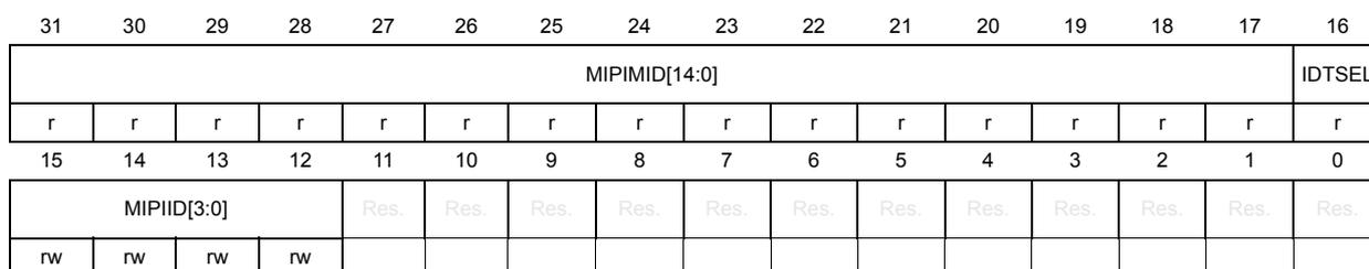
| 31 | 30 | 29 | 28 | 27 | 26 | 25 | 24 | 23 | 22 | 21 | 20 | 19 | 18 | 17 | 16 |
| MIPIMID[14:0] | IDTSEL | ||||||||||||||
| r | r | r | r | r | r | r | r | r | r | r | r | r | r | r | r |
| 15 | 14 | 13 | 12 | 11 | 10 | 9 | 8 | 7 | 6 | 5 | 4 | 3 | 2 | 1 | 0 |
| MIPIID[3:0] | Res. | Res. | Res. | Res. | Res. | Res. | Res. | Res. | Res. | Res. | Res. | Res. | |||
| rw | rw | rw | rw | ||||||||||||
Bits 31:17 MIPIMID[14:0] : 15-bit MIPI manufacturer ID
This read field is the 15-bit STMicroelectronics MIPI ID (0x0104).
This field represents bits[47:33] of the 48-bit provisioned ID.
Bit 16 IDTSEL : provisioned ID type selector
This field is set as 0 (vendor fixed value).
This field represents bit[32] of the 48-bit provisioned ID.
Note: Bits[31:16] of the provisioned ID can be 0.
Bits 15:12 MIPIID[3:0] : 4-bit MIPI Instance ID
This field is written by software to set and identify individually each instance of this I3C IP with a specific number on a single I3C bus.
This field represents bits[15:12] of the 48-bit provisioned ID.
Note: Bits[11:0] of the provisioned ID can be 0.
Bits 11:0 Reserved, must be kept at reset value.
49.16.29 I3C register map
Table 547. I3C register map and reset values
| Offset | Register name | 31 | 30 | 29 | 28 | 27 | 26 | 25 | 24 | 23 | 22 | 21 | 20 | 19 | 18 | 17 | 16 | 15 | 14 | 13 | 12 | 11 | 10 | 9 | 8 | 7 | 6 | 5 | 4 | 3 | 2 | 1 | 0 | ||
|---|---|---|---|---|---|---|---|---|---|---|---|---|---|---|---|---|---|---|---|---|---|---|---|---|---|---|---|---|---|---|---|---|---|---|---|
| 0x000 | I3C_CR | MEND | MTYPE[3:0] | Res. | Res. | Res. | Res. | ADD[6:0] / CCC[7:0] | RNW | DCNT[15:0] | |||||||||||||||||||||||||
| Reset value | 0 | 0 | 0 | 0 | 0 | 0 | 0 | 0 | 0 | 0 | 0 | 0 | 0 | 0 | 0 | 0 | 0 | 0 | 0 | 0 | 0 | 0 | 0 | 0 | 0 | 0 | 0 | 0 | |||||||
| 0x004 | I3C_CFGR | Res. | TSFSET | Res. | Res. | Res. | Res. | Res. | Res. | Res. | Res. | Res. | CFLUSH | CDMAEN | TMODE | SMODE | SFLUSH | SDMAEN | Res. | TXTHRES | TXFLUSH | TXDMAEN | Res. | Res. | RXTHRES | RXFLUSH | RXDMAEN | HJACK | Res. | HKSDAEN | EXITPTRN | RSTPTRN | NOARBH | CRINIT | EN |
| Reset value | 0 | 0 | 0 | 0 | 0 | 0 | 0 | 0 | 0 | 0 | 0 | 0 | 0 | 0 | 0 | 0 | 0 | 0 | 0 | 0 | |||||||||||||||
| 0x010 | I3C_RDR | Res. | Res. | Res. | Res. | Res. | Res. | Res. | Res. | Res. | Res. | Res. | Res. | Res. | Res. | Res. | Res. | Res. | Res. | Res. | Res. | Res. | Res. | Res. | Res. | RDB0[7:0] | |||||||||
| Reset value | 0 | 0 | 0 | 0 | 0 | 0 | 0 | 0 | |||||||||||||||||||||||||||
| 0x014 | I3C_RDWR | RDB3[7:0] | RDB2[7:0] | RDB1[7:0] | RDB0[7:0] | ||||||||||||||||||||||||||||||
| Reset value | 0 | 0 | 0 | 0 | 0 | 0 | 0 | 0 | 0 | 0 | 0 | 0 | 0 | 0 | 0 | 0 | 0 | 0 | 0 | 0 | 0 | 0 | 0 | 0 | 0 | 0 | 0 | 0 | 0 | 0 | 0 | 0 | |||
| 0x018 | I3C_TDR | Res. | Res. | Res. | Res. | Res. | Res. | Res. | Res. | Res. | Res. | Res. | Res. | Res. | Res. | Res. | Res. | Res. | Res. | Res. | Res. | Res. | Res. | Res. | Res. | TDB0[7:0] | |||||||||
| Reset value | 0 | 0 | 0 | 0 | 0 | 0 | 0 | 0 | |||||||||||||||||||||||||||
| 0x01C | I3C_TDWR | TDB3[7:0] | TDB2[7:0] | TDB1[7:0] | TDB0[7:0] | ||||||||||||||||||||||||||||||
| Reset value | 0 | 0 | 0 | 0 | 0 | 0 | 0 | 0 | 0 | 0 | 0 | 0 | 0 | 0 | 0 | 0 | 0 | 0 | 0 | 0 | 0 | 0 | 0 | 0 | 0 | 0 | 0 | 0 | 0 | 0 | 0 | 0 | |||
| 0x020 | I3C_IBIDR | IBIDB3[7:0] | IBIDB2[7:0] | IBIDB1[7:0] | IBIDB0[7:0] | ||||||||||||||||||||||||||||||
| Reset value | 0 | 0 | 0 | 0 | 0 | 0 | 0 | 0 | 0 | 0 | 0 | 0 | 0 | 0 | 0 | 0 | 0 | 0 | 0 | 0 | 0 | 0 | 0 | 0 | 0 | 0 | 0 | 0 | 0 | 0 | 0 | 0 | |||
| 0x024 | I3C_TGTDDR | Res. | Res. | Res. | Res. | Res. | Res. | Res. | Res. | Res. | Res. | Res. | Res. | Res. | Res. | Res. | PRELOAD | TGTTDCNT[15:0] | |||||||||||||||||
| Reset value | 0 | 0 | 0 | 0 | 0 | 0 | 0 | 0 | 0 | 0 | 0 | 0 | 0 | 0 | 0 | 0 | |||||||||||||||||||
| 0x030 | I3C_SR | MID[7:0] | Res. | Res. | Res. | Res. | Res. | Res. | DIR | ABT | Res. | XDCNT[15:0] | |||||||||||||||||||||||
| Reset value | 0 | 0 | 0 | 0 | 0 | 0 | 0 | 0 | 0 | 0 | 0 | 0 | 0 | 0 | 0 | 0 | 0 | 0 | |||||||||||||||||
| 0x034 | I3C_SER | Res. | Res. | Res. | Res. | Res. | Res. | Res. | Res. | Res. | Res. | Res. | Res. | Res. | Res. | Res. | Res. | Res. | Res. | Res. | Res. | Res. | DERR | DNACK | ANACK | COVR | DOVR | STALL | PERR | CODERR[3:0] | |||||
| Reset value | 0 | 0 | 0 | 0 | 0 | 0 | 0 | ||||||||||||||||||||||||||||
| 0x040 | I3C_RMR | Res. | Res. | Res. | Res. | Res. | Res. | Res. | RADD[6:0] | RCODE[7:0] | Res. | Res. | Res. | Res. | Res. | IBIRDCNT[2:0] | |||||||||||||||||||
| Reset value | 0 | 0 | 0 | 0 | 0 | 0 | 0 | 0 | 0 | 0 | 0 | 0 | 0 | 0 | 0 | 0 | 0 | 0 | |||||||||||||||||
| Offset | Register name | 31 | 30 | 29 | 28 | 27 | 26 | 25 | 24 | 23 | 22 | 21 | 20 | 19 | 18 | 17 | 16 | 15 | 14 | 13 | 12 | 11 | 10 | 9 | 8 | 7 | 6 | 5 | 4 | 3 | 2 | 1 | 0 |
|---|---|---|---|---|---|---|---|---|---|---|---|---|---|---|---|---|---|---|---|---|---|---|---|---|---|---|---|---|---|---|---|---|---|
| 0x050 | I3C_EVR | GRPF | DEFF | INTUPDF | ASUPDF | RSTF | MRLUPDF | MWLUPDF | DAUPDF | STAF | GETF | WKPF | Res. | HJF | CRUPDF | CRF | IBIENDF | IBIF | Res. | Res. | Res. | ERRF | RXTGTENDF | FCF | Res. | RXLASTF | TXLASTF | RXFNEF | TXFNEF | SFNEF | CFNEF | TXFEF | CFEF |
| Reset value | 0 | 0 | 0 | 0 | 0 | 0 | 0 | 0 | 0 | 0 | 0 | 0 | 0 | 0 | 0 | 0 | 0 | 0 | 0 | 0 | 0 | 0 | 0 | 0 | 0 | 1 | 1 | ||||||
| 0x054 | I3C_IER | GRPIE | DEFIE | INTUPDIE | ASUPDIE | RSTIE | MRLUPDIE | MWLUPDIE | DAUPDIE | STAIE | GETIE | WKPIE | Res. | HJIE | CRUPDIE | CRIE | IBIENDIE | IBIE | Res. | Res. | Res. | ERRIE | RXTGTENDIE | FCIE | Res. | Res. | Res. | RXFNEIE | TXFNEIE | SFNEIE | CFNEIE | Res. | Res. |
| Reset value | 0 | 0 | 0 | 0 | 0 | 0 | 0 | 0 | 0 | 0 | 0 | 0 | 0 | 0 | 0 | 0 | 0 | 0 | 0 | 0 | 0 | 0 | 0 | ||||||||||
| 0x058 | I3C_CEVR | CGRPF | CDEFF | CINTUPDF | CASUPDF | CRSTF | CMRLUPDF | CMWLUPDF | CDAUPDF | CSTAF | CGETF | CWKPF | Res. | CHJF | CRRUPDF | CCRF | CIBIENDF | CIBIF | Res. | Res. | Res. | CERRF | CRXTGTENDF | CFCF | Res. | Res. | Res. | Res. | Res. | Res. | Res. | Res. | Res. |
| Reset value | 0 | 0 | 0 | 0 | 0 | 0 | 0 | 0 | 0 | 0 | 0 | 0 | 0 | 0 | 0 | 0 | 0 | 0 | 0 | ||||||||||||||
| 0x05C | Reserved | ||||||||||||||||||||||||||||||||
| 0x060 | I3C_DEVR0 | Res. | Res. | Res. | Res. | Res. | Res. | Res. | Res. | RSTVAL | RSTACT[1:0] | AS[1:0] | HJEN | Res. | Res. | CREN | IBIEN | Res. | Res. | Res. | Res. | Res. | Res. | Res. | Res. | DA[6:0] | DAVAL | ||||||
| Reset value | 0 | 0 | 0 | 0 | 0 | 0 | 0 | 0 | 0 | 0 | 0 | 0 | 0 | 0 | 0 | 0 | |||||||||||||||||
| 0x060 + 4 * x, (x = 1 to 4) | I3C_DEVRx | DIS | Res. | Res. | Res. | Res. | Res. | Res. | Res. | Res. | Res. | Res. | SUSP | IBIDEN | CRACK | IBIACK | Res. | Res. | Res. | Res. | Res. | Res. | Res. | Res. | Res. | DA[6:0] | DAVAL | ||||||
| Reset value | 0 | 0 | 0 | 0 | 0 | 0 | 0 | 0 | 0 | 0 | 0 | 0 | 0 | ||||||||||||||||||||
| 0x090 | I3C_MAXRLR | Res. | Res. | Res. | Res. | Res. | Res. | Res. | Res. | Res. | Res. | Res. | Res. | Res. | Res. | IBIP[2:0] | MRL[15:0] | ||||||||||||||||
| Reset value | 0 | 0 | 0 | 0 | 0 | 0 | 0 | 0 | 0 | 0 | 0 | 0 | 0 | 0 | 0 | 0 | 0 | 0 | |||||||||||||||
| 0x094 | I3C_MAXWLR | Res. | Res. | Res. | Res. | Res. | Res. | Res. | Res. | Res. | Res. | Res. | Res. | Res. | Res. | Res. | Res. | MWL[15:0] | |||||||||||||||
| Reset value | 0 | 0 | 0 | 0 | 0 | 0 | 0 | 0 | 0 | 0 | 0 | 0 | 0 | 0 | 0 | 0 | |||||||||||||||||
| 0x0A0 | I3C_TIMINGR0 | SCLH_I2C[7:0] | SCLL_OD[7:0] | SCLH_I3C[7:0] | SCLL_PP[7:0] | ||||||||||||||||||||||||||||
| Reset value | 0 | 0 | 0 | 0 | 0 | 0 | 0 | 0 | 0 | 0 | 0 | 0 | 0 | 0 | 0 | 0 | 0 | 0 | 0 | 0 | 0 | 0 | 0 | 0 | 0 | 0 | 0 | 0 | 0 | 0 | 0 | 0 | |
| 0x0A4 | I3C_TIMINGR1 | Res. | Res. | Res. | SDA_HD | Res. | Res. | Res. | Res. | Res. | FREE[6:0] | Res. | Res. | Res. | Res. | Res. | Res. | ASNCR[1:0] | AVAL[7:0] | ||||||||||||||
| Reset value | 0 | 0 | 0 | 0 | 0 | 0 | 0 | 0 | 0 | 0 | 0 | 0 | 0 | 0 | 0 | 0 | 0 | 0 | |||||||||||||||
| 0x0A8 | I3C_TIMINGR2 | Res. | Res. | Res. | Res. | Res. | Res. | Res. | Res. | Res. | Res. | Res. | Res. | Res. | Res. | Res. | Res. | AVAL[7:0] | Res. | Res. | Res. | Res. | STALLA | STALLC | STALLD | STALLT | |||||||
| Reset value | 0 | 0 | 0 | 0 | 0 | 0 | 0 | 0 | 0 | 0 | 0 | 0 | |||||||||||||||||||||
| 0x0C0 | I3C_BCR | Res. | Res. | Res. | Res. | Res. | Res. | Res. | Res. | Res. | Res. | Res. | Res. | Res. | Res. | Res. | Res. | Res. | Res. | Res. | Res. | Res. | Res. | Res. | Res. | BCR6 | Res. | Res. | Res. | BCR2 | Res. | BCR0 | Res. |
| Reset value | 0 | 0 | 0 | ||||||||||||||||||||||||||||||
Table 547. I3C register map and reset values (continued)
| Offset | Register name | 31 | 30 | 29 | 28 | 27 | 26 | 25 | 24 | 23 | 22 | 21 | 20 | 19 | 18 | 17 | 16 | 15 | 14 | 13 | 12 | 11 | 10 | 9 | 8 | 7 | 6 | 5 | 4 | 3 | 2 | 1 | 0 |
|---|---|---|---|---|---|---|---|---|---|---|---|---|---|---|---|---|---|---|---|---|---|---|---|---|---|---|---|---|---|---|---|---|---|
| 0x0C4 | I3C_DCR | Res. | Res. | Res. | Res. | Res. | Res. | Res. | Res. | Res. | Res. | Res. | Res. | Res. | Res. | Res. | Res. | Res. | Res. | Res. | Res. | Res. | Res. | Res. | DCR[7:0] | ||||||||
| Reset value | 0 | 0 | 0 | 0 | 0 | 0 | 0 | 0 | 0 | ||||||||||||||||||||||||
| 0x0C8 | I3C_GETCAPR | Res. | Res. | Res. | Res. | Res. | Res. | Res. | Res. | Res. | Res. | Res. | Res. | Res. | Res. | Res. | Res. | Res. | CAPPEND | Res. | Res. | Res. | Res. | Res. | Res. | Res. | Res. | Res. | Res. | Res. | Res. | Res. | Res. |
| Reset value | 0 | ||||||||||||||||||||||||||||||||
| 0x0CC | I3C_CRCAPR | Res. | Res. | Res. | Res. | Res. | Res. | Res. | Res. | Res. | Res. | Res. | Res. | Res. | Res. | Res. | Res. | Res. | Res. | Res. | Res. | Res. | CAPGR | Res. | Res. | Res. | Res. | Res. | Res. | CAPDHFF | Res. | Res. | Res. |
| Reset value | 0 | 0 | |||||||||||||||||||||||||||||||
| 0x0D0 | I3C_GETMXDSR | Res. | Res. | Res. | Res. | Res. | Res. | Res. | TSCO | RDTURN[7:0] | Res. | Res. | Res. | Res. | Res. | Res. | FMT[1:0] | Res. | Res. | Res. | Res. | Res. | Res. | HOFFAS [1:0] | |||||||||
| Reset value | 0 | 0 | 0 | 0 | 0 | 0 | 0 | 0 | 0 | 0 | 0 | 0 | |||||||||||||||||||||
| 0x0D4 | I3C_EPIDR | MIPIMID[14:0] | IDTSEL | MIPIID[3:0] | Res. | Res. | Res. | Res. | Res. | Res. | Res. | Res. | Res. | Res. | |||||||||||||||||||
| Reset value | 0 | 0 | 0 | 0 | 0 | 0 | 1 | 0 | 0 | 0 | 0 | 0 | 1 | 0 | 0 | 0 | 0 | 0 | 0 | 0 | 0 | ||||||||||||
Refer to Section 2.3: Memory organization for the register boundary addresses.