4. System security
The STM32H7Rx/7Sx products are designed with a comprehensive set of security features. This section explains the different security features available on STM32H7Rx/7Sx devices.
4.1 Key security features
- •
Secure firmware installation (SFI):
with device unique cryptographic key pair
- – leveraging the on-chip immutable bootloader that supports the download of image through USART, USB, I 2 C, I 3 C, SPI, FDCAN and JTAG
- • Boot entry: the platform allows selection between native immutable root of trust, or proprietary boot entry (in user flash memory).
- • Security services: The platform comes with native security services. The services are embedded in the system memory to manage root of trust services. Native root of trust services takes care of: platform security including secure boot, secure updates of next boot level (uROT: updatable root of trust), secure debug control (debug reopening, regression control). Security services can be personalized for each OEMs. OEM personalization is done thanks to provisioning tools.
- • Temporal isolation: boot levels are isolated thanks to HDPL (hide protect level) monotonic counter.
- •
Secure storage
, featuring:
- – three nonvolatile areas dedicated to secure storage. Areas are protected with HDPL.
- – Battery-powered volatile secure storage, automatically erased in case of tamper
- – Write-only key registers in the AES engines
- – Device 96-bit unique ID
- – Secure storage can rely to SAES engine to encrypt the stored data to benefit of DHUK properties. All data encrypted with the DHUK benefit of temporal isolations (HDPL), RHUK (Root Hardware Unique Key), EPOCH (regression counter) properties.
- a) Data are isolated: each data encrypted/decrypted relying to SAES+DHUK benefit of the variation of the DHUK for each different isolated area (HDPL0, HDPL1, HDPL2)
- b) RHUK: hardware secret nonvolatile unique per device keys (copy protection).
- c) EPOCH: counter incremented each time a regression is done (anti rollback).
- •
General purpose cryptographic acceleration:
- – AES 256-bit engine, supporting ECB, CBC, CTR, GCM and CCM chaining modes
- – Secure AES 256-bit security co-processor, supporting ECB, CBC, CTR, GCM and CCM chaining modes with side-channel counter-measures and mitigations
- – HASH processor, supporting SHA-1 checksums and SHA-2 secure hash (SHA2, SHA2-384, SHA2-512)
- – Public key accelerator (PKA) for RSA/DH (up to 4096 bits) and ECC (up to 640 bits), implementing side-channel counter measures and mitigations when manipulating secrets
- – True random number generator (RNG), NIST SP800-90B pre-certified
- •
3 MCEs:
for memory cypher engine of external memories
- – System bus in-line encryption and decryption
- – Crypto: Support block cyphering AES and Noekeon, and chaining modes and stream mode with AES.
- – Automatic key-erase in case of tamper
- – Optimization for octo-SPI/hexa-SPI/FMC data pre-fetching mechanism.
- • New flexible lifecycle scheme: Allows product maintenance in-the-field (debug re-opening or regressions)
- •
Active tamper and protection:
against temperature, voltage and frequency attacks
- – Up to eight active inputs, eight active output tamper pins, available in different power modes (refer to Section 50.4: TAMP low-power modes ).
4.2 Secure install
The secure firmware install (SFI) is an immutable secure service embedded by STMicroelectronics in the devices. The SFI allows secure and counted installation of OEM firmware in untrusted production environment (such as OEM contract manufacturer).
The confidentiality of the installed images written in the internal flash memory is also protected using the AES.
The SFI native service leverages the following hardware security features:
- • secure boot (see Section 4.3 )
- • temporal isolation using hide protection (see Section 4.5.1 )
- • secure execution (see Section 4.6 )
- • secure storage, with associated cryptographic engines (see Section 4.7 and Section 4.8 ) and flash dedicated areas
Further information can be found in the application note Overview secure firmware install (SFI) (AN4992).
4.3 Secure boot
Secure boot is an immutable code that is always executed after a system reset. As a root of trust, this code checks the device static protections and activates available device runtime protections, reducing the risk that invalid or malicious code runs on the platform. As root of trust, the secure boot also checks the integrity and authenticity of the next level firmware before executing it.
The STM32H7Sx offers two options using IROT_SELECT option byte for the immutable code to be executed after a reset. The STiRoT takes advantage of the security services already embedded in the STM32. The other option allows OEMs to manage the secure boot path:
- • Security services when STiRoT (ST immutable root of trust, code natively present in the system memory) is selected managing the secure boot of the next boot level. STiRoT takes care of the next level integrity, authenticity and updates using configuration done by OEMs. To do so, the H7Sxx STiRoT manages a boot sequence using several system resets to load the first application boot level from external memory to the SRAM, then launch a reset. The loaded image in SRAM is then verified by STiRoT, before the concerned level is launched. STiRoT can also manage the update of such firmware.
- • Proprietary boot entry when the full chain is managed by the OEM (called OEM-iROT). The iROT is to be installed in user flash memory with proper security activation (WRP, HDP).
In the devices, the secure boot takes advantage of hardware security features such as:
- • temporal isolation using hide protection levels (HDPL) (see Section 4.5.1: Temporal isolation using secure hide protection (HDP) )
- • secure install and update (see Section 4.2: Secure install and Section 4.4: Secure update )
- • per-domain secure storage, with associated cryptographic engines if available (see Section 4.7: Secure storage and Section 4.8: Crypto engines )
This section describes the features specifically designed for secure boot.
4.3.1 Unique boot entry
The IROT_SELECT option byte allows boot through the STiRoT or OEM-iROT (user flash memory). This selection is possible only for products embedding cryptographic acceleration (STM32H7Sx).
For more information on the boot mechanisms, see Section 2.6: Boot configuration .
4.3.2 Security services in system flash memory
The security services located in the system flash memory, cover the root secure services (RSS), the STiRoT (immutable root of trust), and ST-DA (debug authentication).
The RSS (root secure service) allows the control of ST extensions loaded in SRAM (called RSS-e). One of the RSS-e manages the SFI (secure firmware Install). SFI allows secure and counted installation of OEM firmware in untrusted production environments (such as OEM contract manufacturer).
The STMicroelectronics immutable code also includes secure runtime services that can be called at runtime when a secure application sets the SBS_RSSCMDR register to a non-null value before triggering a system reset. This runtime feature is deactivated when the product state is different to “Provisioning”.
STM32H7Rx/7Sx products offer the following security services:
- • ST-DA (debug authentication control): This allows control of the product life cycle for field return. It controls debug reopening or regression following OEM choices. It manages the debug authentication control feature, giving control of the debug reopening and regressions of the product for after sales (field return) of the product.
- • RSS and RSS-e SFI: to handle secure provisioning and secure firmware installation in the user flash memory.
STM32H7Sxx products offer the following security services:
- • STiRoT (immutable root of trust). This allows management of the boot of the system, ensuring the secure boot and secure update of the following stage. It handles the secure provisioning, secure boot, secure updates of the first updatable level of the platform. As the product is an “hybrid” between flashless and flash memory, the different boots from STiRoT are based on a multi-reset flow.
For this multi-reset flow, STiRoT secure boot or secure update sequence rely on:
- • An OEM-iLoader that have to be installed in the user flash memory. OEM-iLoader is in charge of loading the first boot level from external memory to the SRAM. If OEM-iLoader detect an update (of the first boot level), it loads it to the SRAM. When an image is ready to be processed by STiRoT, a system reset is launched to let the STiRoT manage the proper action.
- • OEM-iLoader relies on a library to access the external flash memory (external memory management).
Figure 6. Secure boot process
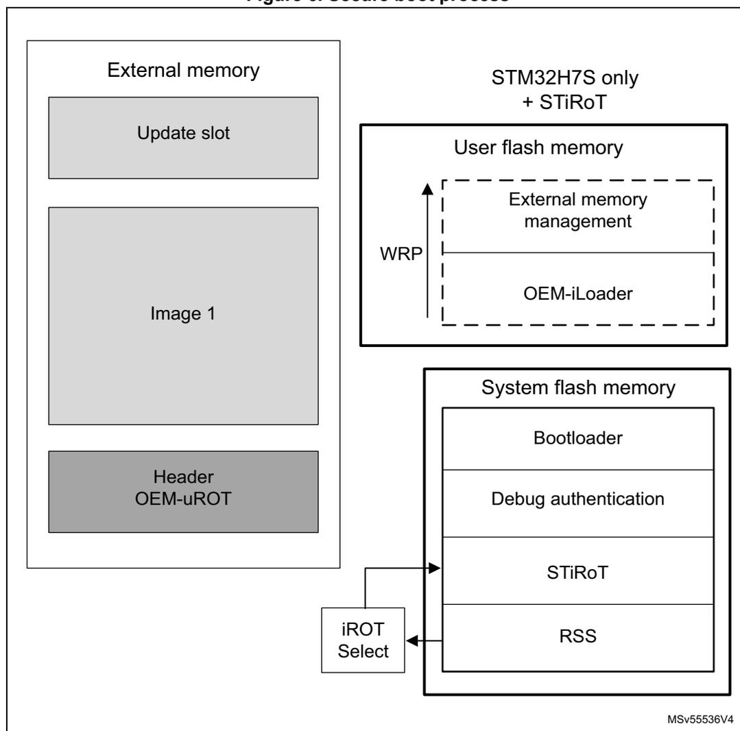
The diagram illustrates the memory layout and components for the secure boot process. It is divided into two main sections: External memory and STM32H7S only + STiRoT.
External memory: Contains three stacked blocks: "Update slot" (top), "Image 1" (middle), and "Header OEM-uROT" (bottom).
STM32H7S only + STiRoT: Contains two main memory blocks. The top block is "User flash memory", which is divided into "External memory management" (top) and "OEM-iLoader" (bottom). A vertical arrow labeled "WRP" (Write Protection) points to the boundary between these two sections. The bottom block is "System flash memory", which is divided into four stacked blocks: "Bootloader" (top), "Debug authentication", "STiRoT", and "RSS" (bottom). A box labeled "iROT Select" is connected to the "STiRoT" block in the system flash memory.
MSV55536V4
A typical secure boot flow is as follows:
Hypothesis: The IROT_SELECT has been set to STiRoT and the STiRoT has been provisioned. OEM-iLoader code has been installed and write protected in user flash memory. The first updatable boot level has been provisioned in the external memory.
Flow execution:
- 1. On the STiRoT initial execution, it verifies then launch the OEM-iLoader.
- 2. Then OEM-iLoader is able to read external memories:
- a) OEM-iLoader checks if an update image is present for the OEM-uROT. If so, it loads it to the SRAM then launch a reset, to let the STiRoT managing the secure controls before install.
- b) If no update image is present then OEM-iLoader loads OEM-uROT from external memory then launch a reset, to let the STiRoT managing the verification of the image before launching it.
4.4 Secure update
The secure update is the capacity of the product to update its firmware, allowing improvement of the product features, or fixing of vulnerabilities.
The product update is considered to be done in almost 2 parts:
- • The iROT takes care of the next updatable level (uROT) hosted in external memory.
- • The uROT must manage the overall application updates.
When STiRoT is selected, the secure update is executed in several steps. See the previous paragraph for more details.
When OEM-iROT is selected, it is hosted in the internal flash memory. It can be partially or fully immutable. It must manage the external memories, including the hardware setup, the secure boot, the secure update of the next updatable level (uROT).
The update process is performed in a secure way to prevent unauthorized updates and access to confidential on-device data.
4.5 Resource isolation using hide protect levels
In the STM32H7Rx/7Sx devices, the hardware and software resources used for boot can be isolated using the temporal isolation proposed with the HDPL (HiDe protect level) mechanism.
It is based on a monotonic counter, which by definition allows only incrementing of the levels. When the counter is incremented, the resources of the previous levels become hidden (code and data).
A typical usage of the HDPL, is to allocate the HDPL=1 to the iROT. Then the HDPL=2 to the uROT (including OEM-iLoader), then the application is executed in HDPL=3.
4.5.1 Temporal isolation using secure hide protection (HDP)
The embedded flash memory allows definition of an HDP area associated to an HDPL with an 8-Kbyte page granularity (defined through the option bytes). The code executed in this HDP area, with its related data and keys, can be hidden after boot until the next system reset.
The hide protection is related to HDPL=1 (hidden when HDPL becomes equal or greater than 2) when OEM-iROT is selected.
The hide protection is related to HDPL=2 (hidden when HDPL become equal or greater than 3) when STiRoT is selected.
Typically, the activation of an HDP area in user flash memory is related to HDPL1. This means that as soon as the HDPL becomes greater than or equal to 2. Then data read, write and instruction fetch (on the area defined by HDP_AREA_START and HDP_AREA_END in FLASH_HDP option bytes), are denied until the next device reset.
Note: Bank erase aborts when it contains a write-protected area (WRP or HDP area).
4.6 Secure execution
Through a mix of special software and hardware features, the devices ensure their correct functional operation under abnormal situations. These can be caused by: programmer errors, software attacks through network access, or local attempt for tampering code execution.
This section describes the hardware features specifically designed for secure execution.
4.6.1 Memory protection unit (MPU)
The Cortex-M7 includes a memory protection unit (MPU) that can restrict read and write accesses to memory regions (including regions mapped to peripherals), based on one or more of the following parameters:
- • Cortex-M7 operating mode (privileged, unprivileged)
- • data/instruction fetch.
4.6.2 Embedded flash memory write protection
The embedded flash memory write protection (WRP) prevents illegal or unwanted write/erase to special sections of the embedded flash memory user area (the system area is permanently write protected).
Any 8 Kbyte sector can be independently write-protected or unprotected by clearing/setting the corresponding WRPS bit in the FLASH_WRPSR register.
The embedded flash memory write-protection user option bits can be modified when HDPL=0 or 1 in the SBS_HDPLSR register, using FLASH_WRPSRP.
Note: Bank erase aborts when it contains a write-protected area (WRP or HDP area).
4.6.3 Tamper detection and response
Principle
The devices include active protection of critical security assets against temperature, voltage and frequency attacks, with the following features:
- • erasure of device secrets upon tamper detection
- • improved guarantee of safe execution for the CPU and its associated security peripherals, including:
- – out-of-range voltage (example: \( V_{BAT} \) , \( V_{DDA} \) ), temperature and clocking (LSE) detection
- – security watchdog IWDG clocked by the internal oscillator LSI
- – possible selection of internal oscillator HSI as system clock
- • power supply protection
- – RTC/TAMP domain powered automatically with \( V_{DD} \) or \( V_{BAT} \)
See Section 50: Tamper and backup registers (TAMP) for more details.
Tamper detection sources
The devices support eight active input/output pins, allowing four independent active-tamper meshes, or up to seven meshes if the same output pin is shared by several input pins (for a total of eight active-tamper I/Os).
The active pins are clocked by the LSE, and are functional in different system operating modes (Run, Sleep, Stop, or Standby), and in VBAT mode. Refer to Section 50.4: TAMP low-power modes for a list of tamper pins and their availability across power modes.
The detection time is programmable, and a digital filtering is available (tamper is triggered after two false comparison in four consecutive comparison samples).
Note: Timestamps are automatically generated when a tamper event occurs.
The internal tamper sources are listed in the table below.
Table 21. Internal tampers in TAMP
| Tamper input | NOER bit number in TAMP_CR3 | Tamper source |
|---|---|---|
| itamp1 | 0 | Backup domain voltage continuous monitoring, functional in VBAT mode |
| itamp2 | 1 | Temperature monitoring, functional in VBAT mode |
| itamp3 | 2 | LSE monitoring (1) , functional in VBAT mode |
| itamp4 | 3 | HSE monitoring |
| itamp5 | 4 | RTC calendar overflow (rtc_calovf) |
| itamp6 | 5 | JTAG/SWD access |
| itamp7, 12, 13 | 6, 11, 12 | Voltage monitoring (V CORE , V REF+ ), through ADC analog watchdog |
| itamp8 | 7 | Monotonic counter overflow (generated internally) |
| itamp9 | 8 | Fault generation for cryptographic peripherals (SAES, PKA, AES, RNG) |
| itamp11 | 10 | IWDG timeout and potential tamper (IWDG reset when at least one enabled tamper flag is set) |
| itamp15 | 14 | System fault detection |
- 1. LSE missing or over frequency detection (> 2 MHz), Glitch filter (> 2 MHz).
Response to tampers
Each source of tamper in the device can be configured to trigger the following events:
- • Generate an interrupt, capable of waking up the device from Stop and Standby modes (see the TAMPxMSK bits in the TAMP_CR2 register).
- • Generate a hardware trigger for the low-power timers.
- • Erase device secrets if the corresponding TAMPxPOM bit is cleared in TAMP_CR2 (for tamper pins) or TAMP_CR3 (for internal tamper). These erasable secrets are:
- – symmetric keys stored in backup registers (x32), in AES, HASH and MCE (encrypted flash memory regions are read as zero)
- – asymmetric keys stored in PKA SRAM, erased when \( V_{DD} \) is present
- – CPU instruction cache memory
- – nonvolatile information used to derive the DHUK in SAES is zeroed
- – 4-Kbyte backup SRAM (depending on configuration bit), erased when \( V_{DD} \) is present
- – MCEs keys.
Read/write accesses by software to all these secrets can be blocked, by setting the BKBLOCK bit in the TAMP_CR2 register. Access to device secrets is possible only when BKBLOCK is cleared, and no tamper flag is set for any enabled tamper source.
If \( V_{DD} \) is not present, the secrets that are erased when \( V_{DD} \) is present are only erased at the next \( V_{DD} \) power on.
Note: Device secret erase is also triggered by setting the BKERASE bit in the TAMP_CR2 register, or by performing a PRODUCT_STATE regression, as defined in Section 4.9.2 . Device secrets are not reset by system reset or when the device wakes up from Standby mode.
Software filtering mechanism
Each tamper source can be configured not to launch an immediate erase, by setting the corresponding TAMPxPOM bit in the TAMP_CR2 register (for external tamper pin), or TAMP_CR3 (for internal tamper).
In such situations, when the tamper flag is raised, access to the secrets below is blocked until all tamper flags are cleared:
- • DHUK in SAES: fixed to a dummy value
- • Backup registers, backup SRAM: read-as-zero, write-ignored
- • AES, SAES and HASH peripherals: automatically reset by RCC
- • PKA peripheral: reset, with memory use blocked (meaning PKA not usable)
- • MCEs: Keys
Once the application is notified by the tamper event, it analyzes the situation. There are two possible cases:
- • The application launches secrets erase with a software command (confirmed tamper).
- • The application just clears the flags to release secrets blocking (false tamper).
Note: If the tamper software fails to react to such a tamper flag, an IWDG reset automatically triggers the erase of secrets.
Tamper detection and low-power modes
The effect of low-power modes on tamper detection are summarized on the table below.
Table 22. Effect of low-power modes on TAMP
| Mode | Description |
|---|---|
| Sleep | No effect on tamper detection features TAMP interrupts cause the device to exit the Sleep mode. |
| Stop | No effect on tamper detection features, except for level detection with filtering and active tamper modes that remain active only when the clock source is LSE or LSI Tamper events cause the device to exit the Stop mode. |
| Standby | No effect on tamper detection features, except for level detection with filtering and active tamper modes which remain active only when the clock source is LSE or LSI Tamper events cause the device to exit the Standby mode. |
Default tamper configuration after reset on closed/locked product states
From SFSP 2.1.0 onward (refer to AN6022), the security services located in the system flash memory activate internal tampers n°9 and n°15 for their security.
As a result, in Closed/Locked product state (where RSS is the unique boot entry), internal tampers n°9 and n°15 stay enabled when STiRoT launches the next-level firmware, but are disabled when RSS jumps directly into OEM-iROT (user flash memory).
4.7 Secure storage
A critical feature of any security system is how long-term keys are stored, protected, and provisioned. Such keys are typically used for loading a boot image, or handling of critical user data.
Figure 7 shows how a key management-service application can use the AES engine, for example to compute external image decryption keys. Nonvolatile keys are stored in a dedicated flash memory area, including access control (see Section 4.5.1 ), while volatile key storage consists of the battery-powered, tamper-protected SRAM or registers-TAMP.
Figure 7 also shows keys that are manipulated by software (such as MCE keys), or keys that are managed only by hardware (such as DHUK). More information on those hardware keys can be found in Section 4.7.1 .
Figure 7. Key management principle
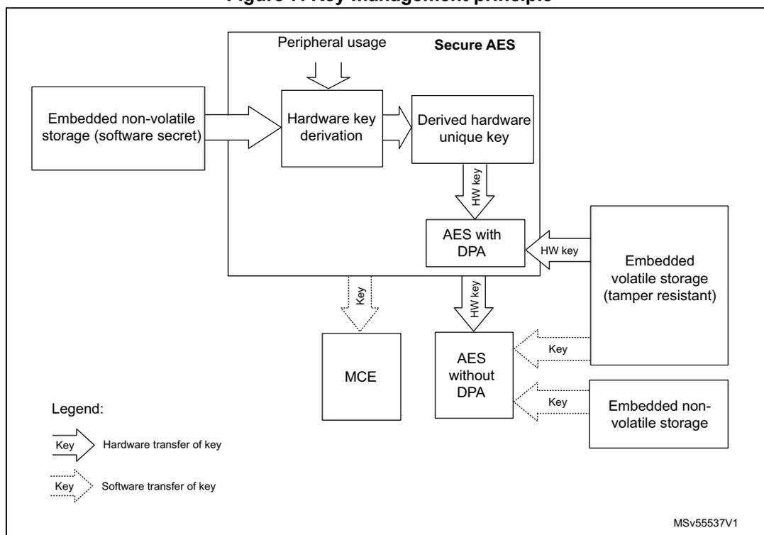
The diagram illustrates the key management principle. It starts with 'Embedded non-volatile storage (software secret)' on the left. An arrow points to 'Hardware key derivation' in the center. From 'Hardware key derivation', an arrow points to 'Derived hardware unique key' in the 'Secure AES' block. Below 'Secure AES' is 'AES with DPA'. Below 'AES with DPA' is 'AES without DPA'. Below 'AES without DPA' is 'MCE'. To the right of 'AES with DPA' is 'Embedded volatile storage (tamper resistant)'. To the right of 'AES without DPA' is 'Embedded non-volatile storage'. Arrows indicate key transfers: 'HW key' from 'Derived hardware unique key' to 'AES with DPA', 'HW key' from 'AES with DPA' to 'Embedded volatile storage', 'HW key' from 'AES without DPA' to 'Embedded non-volatile storage', and 'Key' (software transfer) from 'MCE' to 'Embedded non-volatile storage'. A legend at the bottom left shows a solid arrow for 'Hardware transfer of key' and a dashed arrow for 'Software transfer of key'. The diagram is labeled MSv55537V1.
Details of tamper protection are given in Section 4.6.3 .
4.7.1 Hardware secret key management
As shown in the previous figure, the devices propose a better protection for application keys by using hardware secret keys. These AES keys can be made usable to the application, without exposing them in clear-text (unencrypted). Such keys also become immediately unusable in the case of tamper.
There are three different sources of hardware secret keys:
- • DHUK: derived keys based on 256-bit nonvolatile device unique secret in flash memory. The flash memory provides a value provisioned during product manufacturing (called RHUK). The generation of a DHUK key takes into account the OBK-HDPLx (temporal isolation counter), the EPOCH (regression counter allowing anti-replay protection), and key use state (KMOD).
- • BHK: 256-bit application key stored in tamper-resistant volatile storage in TAMP. This key is written at boot time, then read/write locked to application until next reset.
- • XORK: result of a XOR of BHK and DHUK
These keys can be used in the following modes:
- • as a normal key, loading in write-only key registers (software key mode)
- • as an encryption/decryption key for another key, to be used in the DPA-resistant SAES (wrapped key mode)
- • as an encryption/decryption key for another key, to be used in a faster AES engine (shared key mode).
4.7.2 Unique ID
The devices store a 96-bit ID that is unique to each device (see Section 67.1: Unique device ID register (96 bits) ).
Application services can use this unique identity key to identify the product in the cloud network, or to make it difficult for counterfeit devices or clones to inject untrusted data into the network.
Alternatively, the 256-bit device unique key (DHUK) can be used (see Section 4.7.1 ).
4.8 Crypto engines
The devices implement state-of-the-art cryptographic algorithms featuring key sizes and computing protection as recommended by national security agencies. These agencies include: NIST for the U.S.A, BSI for Germany or ANSSI for France. The algorithms are used to support privacy, authentication, integrity, entropy and identity attestation.
The crypto engines embedded in STM32 reduce weaknesses in the implementation of critical cryptographic functions. They prevent, for example, the use of weak cryptographic algorithms and key sizes. They also enable shorter processing times and lower power consumption when performing cryptographic operations, by offloading those computations from Cortex-M7. This is especially true for asymmetric cryptography.
For product certification purposes, ST can provide certified device information on how these security functions are implemented and validated.
For more information on crypto engine processing times, refer to their respective sections in the reference manual.
4.8.1 Crypto engines features
The table below lists the accelerated cryptographic operations available in the devices. Two AES accelerators are available. One is side-channel attack protected (SAES), while the second is more performance oriented (CRYP).
Note: Additional operations can be added using firmware.
The PKA can accelerate asymmetric crypto operations (like key pair generation, ECC scalar multiplication, point on curve check). See Section 40: Public key accelerator (PKA) for more details.
Table 23. Accelerated cryptographic operations
| Operations | Algorithm | Specification | Key lengths (in bit) | Modes |
|---|---|---|---|---|
| Get entropy | RNG | NIST SP800-90B (1) | N/A | Software and hardware (2) modes running in parallel |
| Encryption, decryption | AES | FIPS PUB 197 NIST SP800-38A | 128, 256 | ECB, CBC, CTR (3) |
| Authenticated encryption or decryption | NIST SP800-38C NIST SP800-38D | 128, 256 | GCM, CCM | |
| Cipher-based message authentication code | NIST SP800-38D | 128, 256 | GMAC |
| Operations | Algorithm | Specification | Key lengths (in bit) | Modes |
|---|---|---|---|---|
| Checksum | SHA-1 | N/A | Digest 160-bit | |
| Cryptographic hash | SHA-2 | FIPS PUB 180-4 | - | SHA-224, SHA-256 SHA2-384, SHA2-512 |
| Keyed-hashing for message authentication | HMAC | FIPS PUB 198-1 IETF RFC 2104 | Short, long (>64 bytes) | - |
| Encryption/decryption key-pair generation (4) | RSA | IETF RFC 8017 NIST SP800-56B | Up to 4160 | RSAES-OAEP |
| Signature
(4)
with hashing Signature verification | RSA | IETF RFC 8017 FIPS PUB 186-4 | Up to 4160 | PKCS1-v1_5, PSS |
| ECDSA | ANSI X9.62 IETF RFC 7027 FIPS PUB 186-4 | Up to 640 | Refer to Table 392: Family of supported curves for ECC operations for details | |
| Key agreement | ECDH | ANSI X9.42 |
- 1. Certifiable using STMicroelectronics reviewed documents.
- 2. Random numbers distribution to SAES and PKA using a dedicated hardware bus.
- 3. ECB and CBC chaining modes protected against side-channel and timing attacks in SAES (see Section 4.8.2 ).
- 4. Private key cryptography protected against side-channel and timing attacks.
Note: Binary curves, Edwards curves and Curve25519 are not supported by the PKA.
4.8.2 Secure AES co-processor (SAES)
The devices provide an on-chip hardware AES encryption and decryption engine, which implements countermeasures and mitigations against power and electromagnetic side-channel attacks.
Clocked by the AHB bus clock, the SAES offers very good performance for a DPA resistant hardware accelerator. The SAES engine supports 128-bit or 256-bit keys in electronic code book (ECB), cipher block chaining (CBC), (CTR), (GCM), (CCM), (GMAC) modes.
As shown in Section 4.7 , the SAES can be used for extra-secure on-chip storage for sensitive information.
For more information, refer to Section 36: Secure AES coprocessor (SAES) .
4.8.3 Memory cipher engine (MCE)
Three MCEs propose on-the-fly encryption and decryption on external non volatile or volatile memories. Up to 4 regions can be defined on each MCE, with a granularity of 4 kbytes. Access filtering can be applied on different regions (privilege, write).
When a tamper event is confirmed in TAMP, all MCE keys are erased.
4.9 Product life cycle
The product life cycle of the STM32H7Rx/7Sx is the result of combining the following settings:
- • the flash interface state: FLASH_NVSRP -> NVSTATE = OPEN /CLOSE
- • the option byte: FLASH_ROTSR->OEM_PRVD = iROT- provisioned or not
- • the option byte: FLASH_ROTSR->DBG_AUTH = select the debug authentication control method, between locked, ECDSA (certificates), and password.
Figure 8. Product life-cycle security
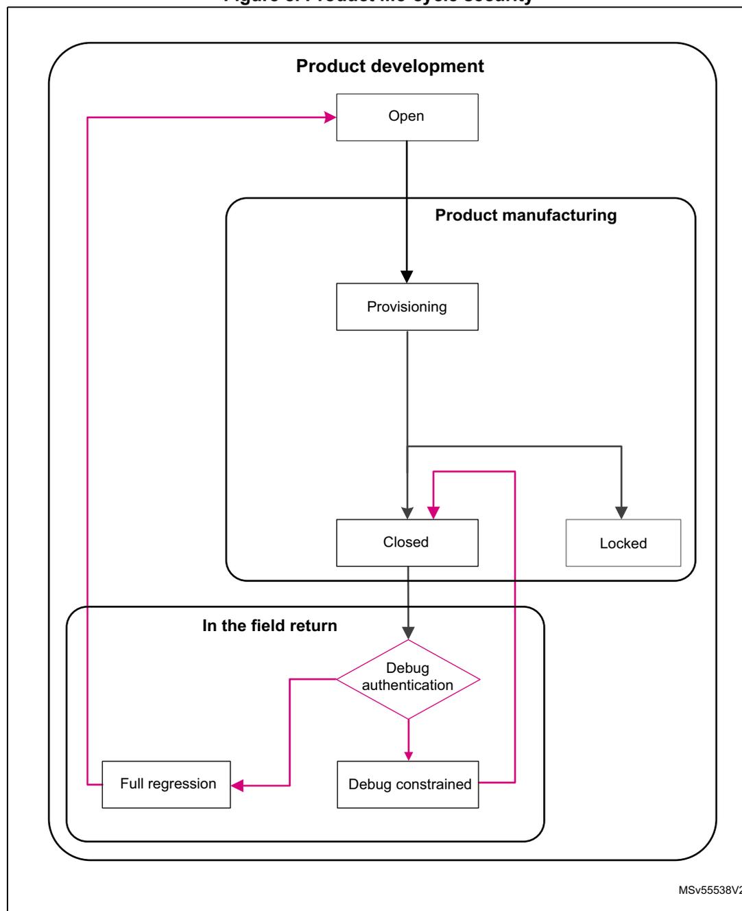
graph TD; subgraph Product_development [Product development]; Open[Open]; end; subgraph Product_manufacturing [Product manufacturing]; Provisioning[Provisioning]; end; subgraph In_the_field_return [In the field return]; Closed[Closed]; Locked[Locked]; Debug_auth{Debug authentication}; Full_regression[Full regression]; Debug_constrained[Debug constrained]; end; Open --> Provisioning; Provisioning --> Closed; Provisioning --> Locked; Closed --> Debug_auth; Debug_auth --> Full_regression; Debug_auth --> Debug_constrained; Debug_constrained --> Open; Full_regression --> Open;The diagram illustrates the product life-cycle security flow for the STM32H7Rx/7Sx. It is divided into three main stages: Product development , Product manufacturing , and In the field return .
- Product development : The process starts with the Open state.
- Product manufacturing : The Open state leads to Provisioning .
- In the field return : From Provisioning , the flow splits into Closed and Locked states. Both lead to a Debug authentication decision point. If Full regression is selected, the flow returns to the Open state in Product development . If Debug constrained is selected, the flow also returns to the Open state in Product development .
MSv55538V2
Table 24. Product life-cycle states
| PRODUCT_STATE | Selecting PRODUCT_STATE | Description |
|---|---|---|
| Open | NVSTATE = OPEN | This state allows product development, as it provides the code debug. Using the boot pin allows the bootloader to be launched. |
| Provisioning | NVSTATE = CLOSE OEM_PROVD=!0xB4 and/or DBG_AUTH = Not set (!0xB4, !0x51, !0x8A) | This state allows product provisioning (partial or full). It allows launching of secure firmware Install, or bootloader to provision the product. Boot from SRAM is not permitted. |
| Closed | NVSTATE = CLOSE OEM_PROVD=0xB4 DBG_AUTH=0x51 or 0x8A | This state considers that the product configuration is finalized. It allows support of debug authentication for in-the-field repair (read the dedicated application note). |
| Locked | NVSTATE = CLOSE OEM_PROVD=0xB4 DBG_AUTH=0xB4 | This state considers that the product configuration is finalized. The debug authentication is not permitted. The product is definitively in this state. |
The features described below contribute to secure the device life-cycle.
4.9.1 Product configurations and security services
The product is provisioned with ST native security services. However, the product can be configured to leave full control of the boot chain to OEMs.
This is done by means of the unique boot entry (FLASH_ROTSRP: IROT_SELECT) option byte. This allows selection between the security services (STiRoT: ST immutable root of trust), or OEM boot implementation (OEM-iROT: OEM immutable root of trust) to be installed in the user part of the flash memory. The product boots on the STiRoT only when the IROT_SELECT is set to STiRoT and when the product state is Closed or Locked.
Security services are provisioned by ST in system flash memory (immutable). They provide the root of trust of the platform managing the verification, and update of the first updatable code (uROT).
STiRoT and OEM-iROT are only available on products embedding cryptographic acceleration (STM32H7Sx).
4.9.2 Recommended product settings
To ease the product maintenance (in-the-field), we recommend taking advantage of the called debug authentication control feature. This enables product maintenance by activating debug, and makes regression management possible, while considering the security of sensitive information.
This implies setting the product state to provisioning state then provision the DA-config and selecting the final product state (closed)
A dedicated application note is available to help when configuring the debug authentication control of the platform.
4.10 System memory
4.10.1 Introduction
System memory stores RSS (root secure services) firmware programmed by ST during production. The RSS provides runtime services to user firmware.
4.10.2 RSS user functions
The RSS provides runtime services thanks to RSS library, whose functions are exposed to user within the CMSIS device header file provided by the STM32CubeH7RS firmware package (see UM3294 Getting started with STM32CubeH7RS for STM32H7Sx/7Rx MCUs).
RSS provides services through the RSSLIB library, dedicated to secure user firmware. Before calling RSSLIB functions, if MPU is enabled, the secure user firmware must:
- • Define a MPU region to have read access on this location, starting from RSSLIB_SYS_FLASH_PFUNC_START (0x1FF1FD4C), up to RSSLIB_SYS_FLASH_PFUNC_END (0x1FF1FD78). These addresses are provided within the CMSIS device header file.
- • Define a MPU region to allow execution of RSSLIB FW, starting from 0x1FF16800 up to 0x1FF17FFF.
Table 25. Macros for RSS services
| C defined macro | Location in system memory |
|---|---|
| RSSLIB_PFUNC | 0x1FF1FD4C |
| - | - |
RSSLIB
The user firmware calls RSSLIB functions using RSSLIB_PFUNC C defined macro, which points to a location within non-secure system memory.
Table 26. RSS lib interface functions
| Library | Callable function |
|---|---|
| RSSLIB_PFUNC | SetSecOB (1) |
| GetRssStatus (1) | |
| SetProductState (1) | |
| DataProvisioning (1) | |
| JumpHDPLvl2 | |
| JumpHDPLvl3 | |
| GetProductState (1) |
1. Functions used for OEM personalization done using provisioning tools.
SetSecOB
Prototype:
uint32_t SetSecOB(uint32_t ObAddr, uint32_t ObMask, uint32_t ObValue,
uint32_t ObPos)
User code function call example:
RSSLIB_PFUNC->SetSecOB((uint32_t) ObAddr, (uint32_t) ObMask, (uint32_t)
ObValue, (uint32_t) ObPos);
Arguments:
- • ObAddr:
- – Input parameter, address of the secure OB to configure, must be one of:
- &(FLASH->WRPSRP)
- &(FLASH->HDPSRP)
- &(FLASH->ROTSRP)
- – Input parameter, address of the secure OB to configure, must be one of:
- • ObMask:
- – Input parameter, mask of the OB part to be updated (example 0x000000FF for updating WRP OB).
- • ObValue:
- – Input parameter, OB value to be applied.
- • ObPos:
- – Input parameter, OB bit shift to be applied on ObValue (ObValue<<ObPos must be aligned on ObMask).
The user calls SetSecOB to configure secure OB, the configuration is done by RSS after reset. This function is only available in provisioning product state.
On successful call, the function does not return and does not push LR onto the stack.
In case of failure (bad product state), SetSecOB returns 0xF5F5F5F5.
To retrieve OB change status (after RSS execution), need to call GetRssStatus function or read back the OB (for example read FLASH_WRPSR register).
GetRssStatus
Prototype:
uint32_t GetRssStatus(void)
User code function call example:
RSSLIB_PFUNC->GetRssStatus();
Arguments: None
The user calls GetRssStatus to get RSS execution status of previous RSSLIB function call that trigger a reset for execution by RSS ( SetSecOB or DataProvisioning ).
Returned values:
| 0xEA EA EA EA | Success |
| 0xF5 F5 F5 F5 | Error |
| 0xF5 F5 E0 E0 | Bad input address range |
| 0xF5 F5 E0 E | Bad size |
| 0xF5 F5 E0 0E | Bad encryption value in DoEncryption |
| 0xF5 F5 08 80 | Hardware cryptography not available (H7R) |
| 0xF5 F5 0E E0 | Encryption error |
| 0xF5 F5 08 08 | Programming error |
| 0xF5 F5 00 08 | Bad value in Destination |
SetProductState
Prototype:
uint32_t SetProductState(uint32_t ProductState)
User code function call example:
RSSLIB_PFUNC->SetProductState((uint32_t) ProductState);
Arguments:
- •
ProductState
:
- – Input parameter, STM32 product state to reach, must be one of:
- 0x17: Provisioning product state, allowed when current product state is Open.
- 0x72: Closed product state, allowed when current product state is Provisioning and Data provisioning has been made.
- – 0x5C: Locked product state, allowed when current product state is Provisioning.
- – Input parameter, STM32 product state to reach, must be one of:
User calls SetProductState to change STM32 product state, the configuration is done by RSS after reset.
On successful call, the function does not return and does not push LR onto the stack.
To retrieve new product state (after RSS execution), need to call GetProductState function.
In the case of failure (bad product state), SetProductState returns 0xF5F5F5F5.
DataProvisioning
Prototype:
uint32_t DataProvisioning(RSSLIB_DataProvisioningConf_t *pConfig)
User code function call example:
RSSLIB_PFUNC->DataProvisioning((RSSLIB_DataProvisioningConf_t*)pConfig));
Arguments:
pConfig : input parameter. RSSLIB_DataProvisioningConf_t
C structure definition is described below:
typedef struct
{
    uint32_t *pSource;
    uint32_t Destination;
    uint32_t Size;
    uint32_t DoEncryption;
    uint32_t Crc;
} RSSLIB_DataProvisioningConf_t;
Structure elements
pSource Provides the address of data to be provisioned. Must be within SRAM3 address range. Destination Provides the destination information (where to provision the data).
0xDADAHHII:- – II provides OBKey starting index.
- – HH provides OBKey HDPL.
- – DADA provides Debug Authentication configuration, only relevant when OBKey HDPL0.
Size Provides the size of data to be provisioned (the number of bytes, must be a multiple of 32). DoEncryption Notifies the DataProvisioning function if it must encrypt or not data within OBKeys.
DoEncrypt can be either 0xF5F5A0AAU or 0xCACA0AA0U (mandatory on STM32H7Rx)- – 0xF5F5A0AAU: notifies the DataProvisioning to encrypt data with relevant AHK before programming it within OBKeys. AHK is selected according to the Destination value.
- – 0xCACA0AA0U: notifies DataProvisioning to program in clear data within OBKeys.
Crc CRC over full source data buffer, pConfig->Destination value, pConfig->Size value and finally pConfig->DoEncryption value.
CRC computation uses CRC-32 (Ethernet):- – CRC polynomial: 0x04C11DB7U
- – Initial value: 0xFFFFFFFFU
Returned values
| 0xEAEAEAEAU | Success |
| 0xF5F5F5F5U | Error: bad product state DataProvisioning only available in Open product state (encryption not supported) and Provisioning product state (encryption supported only on STM32H7Sx). |
| 0xF5F5E0E0U | Error: bad input address range. pConfig or pSource are not in SRAM3 |
| 0xF5F5E0EU | Error: bad provisioning size – Size is not a multiple of 32 – OBKey starting index + Size does not fit within an OBKey section |
| 0xF5F58080U | Error: computed CRC is not the expected one provided within pConfig->CRC |
| 0xF5F5E0EU | Error: wrong DoEncryption parameter value |
| 0xF5F58080U | Error: OBKeys programming error |
| 0xF5F50008U | Error: bad Destination information – OBKey index not in the range 0 to 31 – OBKey HDPL not in the range 0 to 2 (representing HDPL0, HDPL1 and HDPL2) – On OBKey HDPL0, debug authentication not one of ECDSA, PASSWORD or LOCKED |
DataProvisioning receives in input a data buffer and programs it within OBKeys. A CRC prevents any data and parameters tampering issue.
When requested through the pConfig->DoEncryption parameter, DataProvisioning encrypts data before programming them within OBKeys.
DataProvisioning uses AES CBC 128 bits with:
- • IV: defined as (using C definition format)
uint32_t IV = {0x8001D1CEU, 0xD1CED1CEU, 0xD1CE8001U, 0xCED1CED1U}; - • Key: AHK corresponding to the targeted OBKeys HDPL that is randomly generated during the DA (HDPL0) provisioning that must be done first.
Note: Data encryption within OBKeys is supported only by STM32H7S devices.
JumpHDPLv12
Prototype:
uint32_t JumpHDPLv12(uint32_t VectorTableAddr, uint32_t MPUIndex)
User code function call example:
RSSLIB_PFUNC->JumpHDPLv12((uint32_t)NextVectorTableAddr, 1U );
Arguments:
- • VectorTableAddr:
- – Input parameter, address of the next vector table to apply
- – The vector table format is the one used by the Cortex-M7 core
- • MPUIndex:
- – Input parameter, MPU region index, (index 0 to 31 allowed). Caller function must define (but keep disabled) the corresponding MPU region before calling
JumpHDPLvl2. The function enables the MPU region before jumping to the reset handler of the vector table. The vector table reset handler function belongs to the MPU region.
User calls JumpHDPLvl2 to close user Flash HDPL1 area by incrementing HDPL to 2, then jump to the reset handler embedded within the vector table, whose address is passed as input parameter.
After closing HDPL1, JumpHDPLvl2 enables the MPU region provided as input parameter. Once the MPU is enabled, the function sets the SP to the address provided by the passed vector table, and jumps to the reset handler function supported by it. JumpHDPLvl2 does not set the new vector table.
On successful execution, the function does not return and does not push LR onto the stack.
In case of failure (bad input parameter value), JumpHDPLvl2 returns 0xF5F5F5F5.
JumpHDPLvl3
Secure attribute: Secure callable function.
Prototype:
uint32_t JumpHDPLvl3(uint32_t VectorTableAddr, uint32_t MPUIndex)
User code function call example:
RSLLIB_PFUNC->JumpHDPLvl3((uint32_t)NextVectorTableAddr, 1U );
Arguments:
- • VectorTableAddr:
- – Input parameter, address of the next vector table to apply.
- – The vector table format is the one used by the Cortex-M7 core.
- • MPUIndex:
- – Input parameter, MPU region index, (index 0 to 31 allowed). Caller function must define but keep disabled the corresponding MPU region before calling JumpHDPLvl3. The function enables the MPU region before jumping to the reset handler of the vector table, whose function belongs to the MPU region.
User calls JumpHDPLvl3 to close user Flash HDPL1 and HDPL2 areas by incrementing HDPL up to 3, then jump to the reset handler embedded within the vector table, whose address is passed as input parameter.
After closing HDPL1/2, JumpHDPLvl3 enables the MPU region provided as input parameter. Once the MPU region is enabled, the function sets the SP to the address provided by the passed vector table, and jumps to the reset handler function supported by the vector table. JumpHDPLvl3 does not set the new vector table.
On successful execution, the function does not return and does not push LR onto the stack.
In the case of failure (bad input parameter value), JumpHDPLvl3 returns 0xF5F5F5F5.
GetProductState
Prototype:
uint32_t GetProductState(void)
User code function call example:
RSSLIB_PFUNC->GetProductState();
Arguments: None
User calls GetProductState to get STM32 product state.
In case of failure (bad product configuration), GetProductState returns 0xF5F5F5F5 (Bad state).
On successful call, the function return one of the following product state:
- • 0x39: Open product state.
- • 0x17: Provisioning product state.
- • 0x72: Closed product state.
- • 0x5C: Locked product state.