31. Hardware semaphore (HSEM)
31.1 Introduction
The hardware semaphore block provides 32 (32-bit) register based semaphores.
The semaphores can be used to ensure synchronization between different processes running between different cores. The HSEM provides a non-blocking mechanism to lock semaphores in an atomic way. The following functions are provided:
- • Semaphore lock, in two ways:
- – 2-step lock: by writing COREID and PROCID to the semaphore, followed by a read check
- – 1-step lock: by reading the COREID from the semaphore
- • Interrupt generation when a semaphore is unlocked
- – Each semaphore may generate an interrupt on one of the interrupt lines
- • Semaphore clear protection
- – A semaphore is only unlocked when COREID and PROCID match
- • Global semaphore clear per COREID
31.2 Main features
The HSEM includes the following features:
- • 32 (32-bit) semaphores
- • 8-bit PROCID
- • 4-bit COREID
- • One interrupt line per processor
- • Lock indication
31.3 Functional description
31.3.1 HSEM block diagram
As shown in Figure 341 , the HSEM is based on three sub-blocks:
- • the semaphore block containing the semaphore status and IDs
- • the semaphore interface block providing AHB access to the semaphore via the HSEM_Rx and HSEM_RLRx registers
- • the interrupt interface block providing control for the interrupts via HSEM_CnISR, HSEM_CnIER, HSEM_CnMISR, and HSEM_CnICR registers.
Figure 341. HSEM block diagram
![Figure 341. HSEM block diagram. The diagram shows the internal structure of the HSEM block. It consists of three main sub-blocks: 'Semaphore block', 'Semaphore interface', and 'Interrupt interface'. The 'Semaphore block' contains multiple semaphores (Semaphore 0, Semaphore 1, ..., Semaphore x). The 'Semaphore interface' contains registers HSEM_R0, HSEM_RLR0, HSEM_R1, HSEM_RLR1, ..., HSEM_Rx, HSEM_RLRx. The 'Interrupt interface' contains registers HSEM_CnISR[1:0], HSEM_CnIER[1:0], HSEM_CnMISR[1:0], and HSEM_CnICR[1:0]. The 'Semaphore block' is connected to the 'Semaphore interface' via 'Sem_Ints' signals. The 'Semaphore interface' is connected to the 'Interrupt interface' via 'Sem_Ints' signals. The 'Semaphore interface' is also connected to the '32-bit AHB bus' via 'Bus master ID'. The 'hclk' signal is connected to the 'Semaphore block'. The 'Interrupt interface' outputs 'hsem_int1_it' and 'hsem_int2_it' signals. The diagram is labeled MS40530V5.](/RM0471-STM32WB50CG-30CE/c069a020c1c246fe8f946effdf4ec416_img.jpg)
31.3.2 HSEM internal signals
Table 184. HSEM internal input/output signals
| Signal name | Signal type | Description |
|---|---|---|
| AHB bus | Digital input/output | AHB register access bus |
| BusMasterID | Digital input | AHB bus master ID |
| hsem_intn_it | Digital output | Interrupt n line (n = 1 to 2) |
31.3.3 HSEM lock procedures
There are two lock procedures, namely 2-step (write) lock and 1-step (read) lock. The two procedures can be used concurrently.
The semaphore is free when its LOCK bit is 0. In this case, the COREID and PROCID are also 0. When the LOCK bit is 1, the semaphore is locked and the COREID indicates which AHB bus master ID has locked it. The PROCID indicates which process of that AHB bus master ID has locked the semaphore.
When write locking a semaphore, the written COREID must match the AHB bus master ID, and the PROCID is written by the AHB bus master software process taking the lock.
When read locking the semaphore, the COREID is taken from the AHB bus master ID, and the PROCID is forced to 0 by hardware. There is no PROCID available with read lock.
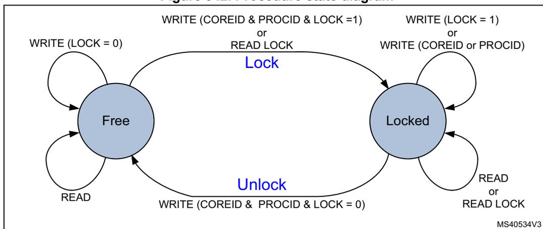
Figure 342. Procedure state diagram
stateDiagram-v2
    Free --> Free : WRITE (LOCK = 0)
    Free --> Free : READ
    Free --> Locked : WRITE (COREID & PROCID & LOCK = 1) or READ LOCK
    Locked --> Locked : WRITE (LOCK = 1) or WRITE (COREID or PROCID)
    Locked --> Locked : READ or READ LOCK
    Locked --> Free : WRITE (COREID & PROCID & LOCK = 0)
The diagram illustrates the state transitions for a hardware semaphore. It has two states: Free and Locked .
- Free State:
- Self-loop: WRITE (LOCK = 0)
- Self-loop: READ
- Transition to Locked (labeled Lock ): WRITE (COREID & PROCID & LOCK = 1) or READ LOCK
- Locked State:
- Self-loop: WRITE (LOCK = 1) or WRITE (COREID or PROCID)
- Self-loop: READ or READ LOCK
- Transition to Free (labeled Unlock ): WRITE (COREID & PROCID & LOCK = 0)
2-step (write) lock procedure
The 2-step lock procedure consists in a write to lock the semaphore, followed by a read to check if the lock has been successful, carried out from the HSEM_R x register.
- • Write semaphore with PROCID and COREID, and LOCK = 1. The COREID data written by software must match the AHB bus master information, that is, a AHB bus master ID = 1 writes data COREID = 1.
Lock is put in place when the semaphore is free at write time. - • Read-back the semaphore
The software checks the lock status, if PROCID and COREID match the written data, then the lock is confirmed. - • Else retry (the semaphore has been locked by another process, AHB bus master ID).
A semaphore can only be locked when it is free.
A semaphore can be locked when the PROCID = 0.
Consecutive write attempts with LOCK = 1 to a locked semaphore are ignored.
1-step (read) lock procedure
The 1-step procedure consists in a read to lock and check the semaphore in a single step, carried out from the HSEM_RLRx register.
- • Read lock semaphore with the AHB bus master COREID.
- • If read COREID matches and PROCID = 0, then lock is put in place. If COREID matches and PROCID is not 0, this means that another process from the same COREID has locked the semaphore with a 2-step (write) procedure.
- • Else retry (the semaphore has been locked by another process, AHB bus master ID).
A semaphore can only be locked when it is free. When read locking a free semaphore, PROCID is 0. Read locking a locked semaphore returns the COREID and PROCID that locked it. All read locks, including the first one that locks the semaphore, return the COREID that locks or locked the semaphore.
Note: The 1-step procedure must not be used when running multiple processes of the same AHB bus master ID. All processes using the same semaphore read the same status. When only one process locks the semaphore, each process of that AHB bus master ID reads the semaphore as locked by itself with the COREID.
31.3.4 HSEM write/read/read lock register address
For each semaphore, two AHB register addresses are provided, separated in two banks of 32-bit semaphore registers, spaced by a 0x80 address offset.
In the first register address bank the semaphore can be written (locked/unlocked) and read through the HSEM_Rx registers.
In the second register address bank the semaphore can be read (locked) through the HSEM_RLRx registers.
31.3.5 HSEM unlock procedures
Unlocking a semaphore is a protected process, to prevent accidental clearing by a AHB bus master ID or by a process not having the semaphore lock right. The procedure consists in writing to the semaphore HSEM_Rx register with the corresponding COREID and PROCID and LOCK = 0. When unlocked the semaphore, the COREID, and the PROCID are all 0.
When unlocked, an interrupt may be generated to signal the event. To this end, the semaphore interrupt must be enabled.
The unlock procedure consists in a write to the semaphore HSEM_Rx register with matching COREID regardless on how the semaphore has been locked (1- or 2-step).
- • Write semaphore with PROCID, COREID, and LOCK = 0
- • If the written data matches the semaphore PROCID and COREID and the AHB bus master ID , the semaphore is unlocked and an interrupt may be generated when enabled, else write is ignored, semaphore remains locked and no interrupt is generated (the semaphore is locked by another process, AHB bus master ID or the written data does not match the AHB bus master signaling).
Note: Different processes of the same AHB bus master ID can write any PROCID value. Preventing other processes of the same AHB bus master ID from unlocking a semaphore must be ensured by software, handling the PROCID correctly.
31.3.6 HSEM COREID semaphore clear
All semaphores locked by a COREID can be unlocked at once by using the HSEM_CR register. Write COREID and correct KEY value in HSEM_CR. All locked semaphores with a matching COREID are unlocked, and may generate an interrupt when enabled.
Note: This procedure may be used in case of an incorrect functioning AHB bus master ID, where another AHB bus master can unlock the locked semaphores by writing the COREID of the incorrect functioning processor into the HSEM_CR register with the correct KEY value. This unlocks all locked semaphores with a matching COREID.
An interrupt may be generated for the unlocked semaphore(s). To this end, the semaphore interrupt must be enabled in the HSEM_CnIER registers.
31.3.7 HSEM interrupts
An interrupt line hsem_intn_it per processor allows each semaphore to generate an interrupt.
An interrupt line provides the following features per semaphore:
- • interrupt enable
- • interrupt clear
- • interrupt status
- • masked interrupt status
With the interrupt enable (HSEM_CnIER) the semaphores affecting the interrupt line can be enabled. Disabled (masked) semaphore interrupts do not set the masked interrupt status MISF for that semaphore, and do not generate an interrupt on the interrupt line.
The interrupt clear (HSEM_CnICR) clears the interrupt status ISF and masked interrupt status MISF of the associated semaphore for the interrupt line.
The interrupt status (HSEM_CnISR) mirrors the semaphore interrupt status ISF before the enable.
The masked interrupt status (HSEM_CnMISR) only mirrors the semaphore enabled interrupt status MISF on the interrupt line. All masked interrupt status MISF of the enabled semaphores need to be cleared to clear the interrupt line.
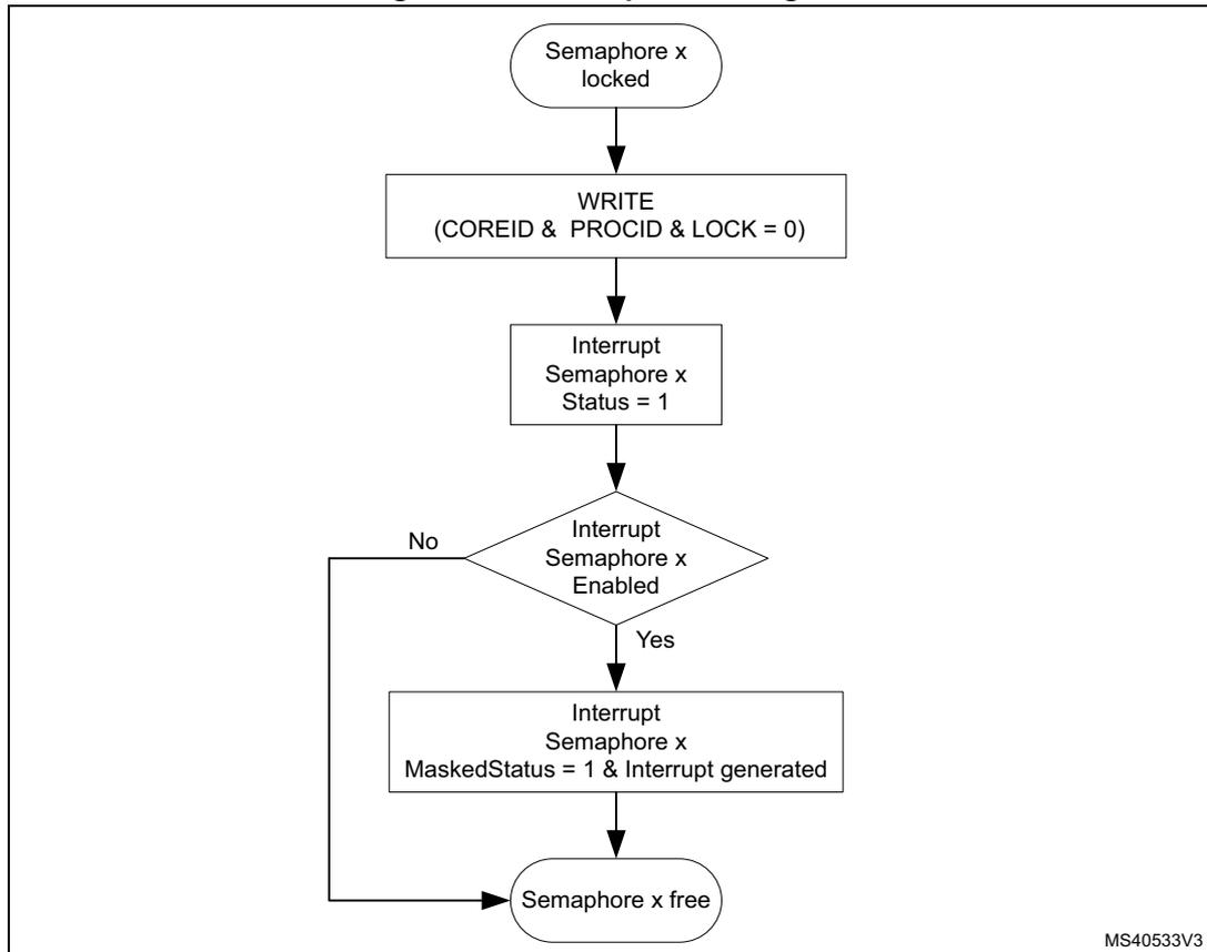
Figure 343. Interrupt state diagram
graph TD
    Start([Semaphore x locked]) --> WRITE[WRITE
(COREID & PROCID & LOCK = 0)]
    WRITE --> InterruptStatus[Interrupt
Semaphore x
Status = 1]
    InterruptStatus --> Enabled{Interrupt
Semaphore x
Enabled}
    Enabled -- No --> Free([Semaphore x free])
    Enabled -- Yes --> InterruptGenerated[Interrupt
Semaphore x
MaskedStatus = 1 & Interrupt generated]
    InterruptGenerated --> Free
MS40533V3
The procedure to get an interrupt when a semaphore becomes free is described hereafter.
Try to lock semaphore x
- • If the semaphore lock is obtained, no interrupt is needed.
- • If the semaphore lock fails:
- – Clear pending semaphore x interrupt status for the interrupt line in HSEM_CnICR.
- – Re-try to lock the semaphore x again:
- – If the semaphore lock is obtained, no interrupt is needed (semaphore has been freed between first try to lock and clear semaphore interrupt status).
- – If the semaphore lock fails, enable the semaphore x interrupt in HSEM_CnIER.
On semaphore x free interrupt, try to lock semaphore x
- • If the semaphore lock is obtained:
- – Disable the semaphore x interrupt in HSEM_CnIER.
- – Clear pending semaphore x interrupt status in HSEM_CnICR.
- • If the semaphore x lock fails:
- – Clear pending semaphore x interrupt status in HSEM_CnICR.
- – Try again to lock the semaphore x:
- – If the semaphore lock is obtained (semaphore has been freed between first try to lock and semaphore interrupt status clear), disable the semaphore interrupt in HSEM_CnIER.
- – If the semaphore lock fails, wait for semaphore free interrupt.
Note: An interrupt does not lock the semaphore. After an interrupt, either the AHB bus master or the process must still perform the lock procedure to lock the semaphore.
It is possible to have multiple AHB bus masters informed by the semaphore free interrupts. Each AHB bus master gets its interrupt, and the first one to react locks the semaphore.
31.3.8 AHB bus master ID verification
The HSEM allows only authorized AHB bus master IDs to lock and unlock semaphores.
- • The AHB bus master 2-step lock write access to the semaphore HSEM_Rx register is checked against the valid bus master IDs.
- – Accesses from unauthorized AHB bus master IDs are discarded and do not lock the semaphore.
- • The AHB bus master 1-step lock read access from the semaphore HSEM_RLRx register is checked against the valid bus master IDs.
- – An unauthorized AHB bus master ID read from HSEM_RLRx returns all 0.
- • The semaphore unlock write access to the HSEM_CR register is checked against the valid bus master IDs. Only the valid bus master IDs can write to the HSEM_CR register and unlock any of the COREID semaphores.
- – Accesses from unauthorized AHB bus master IDs are discarded and do not clear the COREID semaphores.
Table 185 details the relation between bus master/processor and COREID.
Table 185. Authorized AHB bus master IDs
| Bus master 0 (processor1) | Bus master 1 (processor2) |
|---|---|
| COREID = 4 | COREID = 8 |
Note: Accesses from unauthorized AHB bus master IDs to other registers are granted.
31.4 HSEM registers
Registers must be accessed using word format. Byte and half-word accesses are ignored and have no effect on the semaphores, they generate a bus error.
31.4.1 HSEM register semaphore x (HSEM_Rx)
Address offset: \( 0x000 + 0x4 * x \) ( \( x = 0 \) to \( 31 \) )
Reset value: \( 0x0000\ 0000 \)
The HSEM_Rx must be used to perform a 2-step write lock, read back, and for unlocking a semaphore. Only write accesses with authorized AHB bus master IDs are granted. Write accesses with unauthorized AHB bus master IDs are discarded.
| 31 | 30 | 29 | 28 | 27 | 26 | 25 | 24 | 23 | 22 | 21 | 20 | 19 | 18 | 17 | 16 |
|---|---|---|---|---|---|---|---|---|---|---|---|---|---|---|---|
| LOCK | Res. | Res. | Res. | Res. | Res. | Res. | Res. | Res. | Res. | Res. | Res. | Res. | Res. | Res. | Res. |
| rw | |||||||||||||||
| 15 | 14 | 13 | 12 | 11 | 10 | 9 | 8 | 7 | 6 | 5 | 4 | 3 | 2 | 1 | 0 |
| Res. | Res. | Res. | Res. | COREID[3:0] | PROCID[7:0] | ||||||||||
| rw | rw | rw | rw | rw | rw | rw | rw | rw | rw | rw | rw | ||||
Bit 31 LOCK : Lock indication
This bit can be written and read by software.
0: On write free semaphore (only when COREID and PROCID match), on read semaphore is free.
1: On write try to lock semaphore, on read semaphore is locked.
Bits 30:13 Reserved, must be kept at reset value.
Bit 12 Reserved, must be kept at reset value.
Bits 11:8 COREID[3:0] : Semaphore COREID
Written by software
- - When the semaphore is free and the LOCK bit is at the same time written to 1 and the COREID matches the AHB bus master ID.
- - When the semaphore is unlocked (LOCK written to 0 and AHB bus master ID matched COREID, the COREID is cleared to 0.
- - When the semaphore is unlocked (LOCK bit written to 0 or AHB bus master ID does not match COREID, the COREID is not affected.
- - Write when LOCK bit is already 1 (semaphore locked), the COREID is not affected.
- - An authorized read returns the stored COREID value.
Bits 7:0 PROCID[7:0] : Semaphore PROCID
Written by software
- - When the semaphore is free and the LOCK is written to 1, and the COREID matches the AHB bus master ID, PROCID is set to the written data.
- - When the semaphore is unlocked, LOCK written to 0 and AHB bus master ID matched COREID, the PROCID is cleared to 0.
- - When the semaphore is unlocked, LOCK bit written to 0 and AHB bus master ID does not match COREID, the PROCID is not affected.
- - Write when LOCK bit is already 1 (semaphore locked), the PROCID is not affected.
- - An authorized read returns the stored PROCID value.
31.4.2 HSEM read lock register semaphore x (HSEM_RLRx)
Address offset: \( 0x080 + 0x4 * x \) ( \( x = 0 \) to \( 31 \) )
Reset value: \( 0x0000\ 0000 \)
Accesses the same physical bits as HSEM_Rx. The HSEM_RLRx must be used to perform a 1-step read lock. Only read accesses with authorized AHB bus master IDs are granted. Read accesses with unauthorized AHB bus master IDs are discarded and return 0.
| 31 | 30 | 29 | 28 | 27 | 26 | 25 | 24 | 23 | 22 | 21 | 20 | 19 | 18 | 17 | 16 |
|---|---|---|---|---|---|---|---|---|---|---|---|---|---|---|---|
| LOCK | Res. | Res. | Res. | Res. | Res. | Res. | Res. | Res. | Res. | Res. | Res. | Res. | Res. | Res. | Res. |
| r | |||||||||||||||
| 15 | 14 | 13 | 12 | 11 | 10 | 9 | 8 | 7 | 6 | 5 | 4 | 3 | 2 | 1 | 0 |
| Res. | Res. | Res. | Res. | COREID[3:0] | PROCID[7:0] | ||||||||||
| r | r | r | r | r | r | r | r | r | r | r | r | ||||
Bit 31 LOCK : Lock indication
This bit is read only by software at this address.
- When the semaphore is free:
A read with a valid AHB bus master ID locks the semaphore and returns 1.
- When the semaphore is locked:
A read with a valid AHB bus master ID returns 1 (the COREID and PROCID reflect the already locked semaphore information).
Bits 30:13 Reserved, must be kept at reset value.
Bit 12 Reserved, must be kept at reset value.
Bits 11:8 COREID[3:0] : Semaphore COREID
This field is read only by software at this address.
On a read, when the semaphore is free, the hardware sets the COREID to the AHB bus master ID reading the semaphore. The COREID of the AHB bus master locking the semaphore is read.
On a read when the semaphore is locked, this field returns the COREID of the AHB bus master that has locked the semaphore.
Bits 7:0 PROCID[7:0] : Semaphore processor ID
This field is read only by software at this address.
- On a read when the semaphore is free:
A read with a valid AHB bus master ID locks the semaphore and hardware sets the PROCID to 0.
- When the semaphore is locked:
A read with a valid AHB bus master ID returns the PROCID of the AHB bus master that has locked the semaphore.
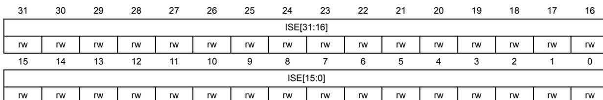
31.4.3 HSEM interrupt enable register (HSEM_CnIER)
Address offset: \( 0x100 + 0x010 * (n - 1) \) , ( \( n = 1 \) to \( 2 \) )
Reset value: 0x0000 0000
| 31 | 30 | 29 | 28 | 27 | 26 | 25 | 24 | 23 | 22 | 21 | 20 | 19 | 18 | 17 | 16 |
| ISE[31:16] | |||||||||||||||
| rw | rw | rw | rw | rw | rw | rw | rw | rw | rw | rw | rw | rw | rw | rw | rw |
| 15 | 14 | 13 | 12 | 11 | 10 | 9 | 8 | 7 | 6 | 5 | 4 | 3 | 2 | 1 | 0 |
| ISE[15:0] | |||||||||||||||
| rw | rw | rw | rw | rw | rw | rw | rw | rw | rw | rw | rw | rw | rw | rw | rw |
Bits 31:0 ISE[31:0] : Interrupt(n) semaphore x enable bit ( \( x = 0 \) to \( 31 \) )
This bit is read and written by software.
0: Interrupt(n) generation for semaphore x disabled (masked)
1: Interrupt(n) generation for semaphore x enabled (not masked)
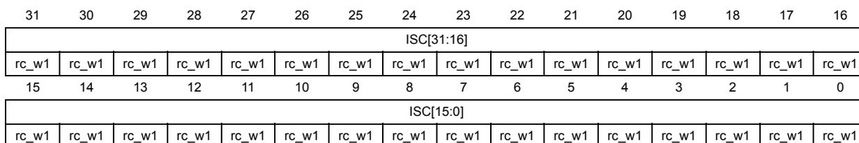
31.4.4 HSEM interrupt clear register (HSEM_CnICR)
Address offset: \( 0x104 + 0x010 * (n - 1) \) , ( \( n = 1 \) to \( 2 \) )
Reset value: 0x0000 0000
| 31 | 30 | 29 | 28 | 27 | 26 | 25 | 24 | 23 | 22 | 21 | 20 | 19 | 18 | 17 | 16 |
| ISC[31:16] | |||||||||||||||
| rc_w1 | rc_w1 | rc_w1 | rc_w1 | rc_w1 | rc_w1 | rc_w1 | rc_w1 | rc_w1 | rc_w1 | rc_w1 | rc_w1 | rc_w1 | rc_w1 | rc_w1 | rc_w1 |
| 15 | 14 | 13 | 12 | 11 | 10 | 9 | 8 | 7 | 6 | 5 | 4 | 3 | 2 | 1 | 0 |
| ISC[15:0] | |||||||||||||||
| rc_w1 | rc_w1 | rc_w1 | rc_w1 | rc_w1 | rc_w1 | rc_w1 | rc_w1 | rc_w1 | rc_w1 | rc_w1 | rc_w1 | rc_w1 | rc_w1 | rc_w1 | rc_w1 |
Bits 31:0 ISC[31:0] : Interrupt(n) semaphore x clear bit ( \( x = 0 \) to \( 31 \) )
This bit is written by software, and is always read 0.
0: Interrupt(n) semaphore x status ISFx and masked status MISFx not affected.
1: Interrupt(n) semaphore x status ISFx and masked status MISFx cleared.
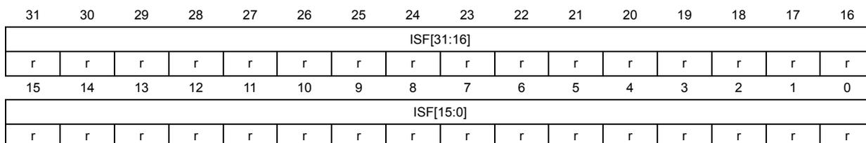
31.4.5 HSEM interrupt status register (HSEM_CnISR)
Address offset: \( 0x108 + 0x010 * (n - 1) \) , ( \( n = 1 \) to \( 2 \) )
Reset value: 0x0000 0000
| 31 | 30 | 29 | 28 | 27 | 26 | 25 | 24 | 23 | 22 | 21 | 20 | 19 | 18 | 17 | 16 |
| ISF[31:16] | |||||||||||||||
| r | r | r | r | r | r | r | r | r | r | r | r | r | r | r | r |
| 15 | 14 | 13 | 12 | 11 | 10 | 9 | 8 | 7 | 6 | 5 | 4 | 3 | 2 | 1 | 0 |
| ISF[15:0] | |||||||||||||||
| r | r | r | r | r | r | r | r | r | r | r | r | r | r | r | r |
Bits 31:0 ISF[31:0] : Interrupt semaphore x status bit before enable (mask) (x = 0 to 31)
This bit is set by hardware, and reset only by software. This bit is cleared by software writing the corresponding HSEM_CnICR bit.
0: Interrupt semaphore x status, no interrupt pending
1: Interrupt semaphore x status, interrupt pending
31.4.6 HSEM interrupt status register (HSEM_CnMISR)
Address offset: 0x10C + 0x010 * (n - 1), (n = 1 to 2)
Reset value: 0x0000 0000
| 31 | 30 | 29 | 28 | 27 | 26 | 25 | 24 | 23 | 22 | 21 | 20 | 19 | 18 | 17 | 16 |
|---|---|---|---|---|---|---|---|---|---|---|---|---|---|---|---|
| MISF[31:16] | |||||||||||||||
| r | r | r | r | r | r | r | r | r | r | r | r | r | r | r | r |
| 15 | 14 | 13 | 12 | 11 | 10 | 9 | 8 | 7 | 6 | 5 | 4 | 3 | 2 | 1 | 0 |
| MISF[15:0] | |||||||||||||||
| r | r | r | r | r | r | r | r | r | r | r | r | r | r | r | r |
Bits 31:0 MISF[31:0] : Masked interrupt(n) semaphore x status bit after enable (mask) (x = 0 to 31)
This bit is set by hardware and read only by software. This bit is cleared by software writing the corresponding HSEM_CnICR bit. This bit is read as 0 when semaphore x status is masked in HSEM_CnIER bit x.
0: interrupt(n) semaphore x status after masking not pending
1: interrupt(n) semaphore x status after masking pending
31.4.7 HSEM clear register (HSEM_CR)
Address offset: 0x140
Reset value: 0x0000 0000
Only write accesses with authorized AHB bus master IDs are granted. Write accesses with unauthorized AHB bus master IDs are discarded.
| 31 | 30 | 29 | 28 | 27 | 26 | 25 | 24 | 23 | 22 | 21 | 20 | 19 | 18 | 17 | 16 |
|---|---|---|---|---|---|---|---|---|---|---|---|---|---|---|---|
| KEY[15:0] | |||||||||||||||
| w | w | w | w | w | w | w | w | w | w | w | w | w | w | w | w |
| 15 | 14 | 13 | 12 | 11 | 10 | 9 | 8 | 7 | 6 | 5 | 4 | 3 | 2 | 1 | 0 |
| Res. | Res. | Res. | Res. | COREID[3:0] | Res. | Res. | Res. | Res. | Res. | Res. | Res. | Res. | |||
| w | w | w | w | ||||||||||||
Bits 31:16 KEY[15:0] : Semaphore clear key
This field can be written by software and is always read 0.
If this key value does not match HSEM_KEYR.KEY, semaphores are not affected.
If this key value matches HSEM_KEYR.KEY, all semaphores matching the COREID are cleared to the free state.
Bits 15:13 Reserved, must be kept at reset value.
Bit 12 Reserved, must be kept at reset value.
Bits 11:8 COREID[3:0] : COREID of semaphores to be cleared
This field can be written by software and is always read 0.
This field indicates the COREID for which the semaphores are cleared when writing the HSEM_CR.
Bits 7:0 Reserved, must be kept at reset value.
31.4.8 HSEM clear semaphore key register (HSEM_KEYR)
Address offset: 0x144
Reset value: 0x0000 0000
| 31 | 30 | 29 | 28 | 27 | 26 | 25 | 24 | 23 | 22 | 21 | 20 | 19 | 18 | 17 | 16 |
|---|---|---|---|---|---|---|---|---|---|---|---|---|---|---|---|
| KEY[15:0] | |||||||||||||||
| rw | rw | rw | rw | rw | rw | rw | rw | rw | rw | rw | rw | rw | rw | rw | rw |
| 15 | 14 | 13 | 12 | 11 | 10 | 9 | 8 | 7 | 6 | 5 | 4 | 3 | 2 | 1 | 0 |
| Res. | Res. | Res. | Res. | Res. | Res. | Res. | Res. | Res. | Res. | Res. | Res. | Res. | Res. | Res. | Res. |
Bits 31:16 KEY[15:0] : Semaphore clear key
This field can be written and read by software.
Key value to match when clearing semaphores.
Bits 15:0 Reserved, must be kept at reset value.
31.4.9 HSEM register map
Table 186. HSEM register map and reset values
| Offset | Register name | 31 | 30 | 29 | 28 | 27 | 26 | 25 | 24 | 23 | 22 | 21 | 20 | 19 | 18 | 17 | 16 | 15 | 14 | 13 | 12 | 11 | 10 | 9 | 8 | 7 | 6 | 5 | 4 | 3 | 2 | 1 | 0 |
|---|---|---|---|---|---|---|---|---|---|---|---|---|---|---|---|---|---|---|---|---|---|---|---|---|---|---|---|---|---|---|---|---|---|
| 0x000 | HSEM_R0 | LOCK | Res. | Res. | Res. | Res. | Res. | Res. | Res. | Res. | Res. | Res. | Res. | Res. | Res. | Res. | Res. | Res. | Res. | Res. | Res. | COREID [3:0] | PROCID[7:0] | ||||||||||
| Reset value | 0 | 0 | 0 | 0 | 0 | 0 | 0 | 0 | 0 | 0 | 0 | 0 | 0 | ||||||||||||||||||||
| 0x004 | HSEM_R1 | LOCK | Res. | Res. | Res. | Res. | Res. | Res. | Res. | Res. | Res. | Res. | Res. | Res. | Res. | Res. | Res. | Res. | Res. | Res. | Res. | COREID [3:0] | PROCID[7:0] | ||||||||||
| Reset value | 0 | 0 | 0 | 0 | 0 | 0 | 0 | 0 | 0 | 0 | 0 | 0 | 0 | ||||||||||||||||||||
| ⋮ | |||||||||||||||||||||||||||||||||
| 0x07C | HSEM_R31 | LOCK | Res. | Res. | Res. | Res. | Res. | Res. | Res. | Res. | Res. | Res. | Res. | Res. | Res. | Res. | Res. | Res. | Res. | Res. | Res. | COREID [3:0] | PROCID[7:0] | ||||||||||
| Reset value | 0 | 0 | 0 | 0 | 0 | 0 | 0 | 0 | 0 | 0 | 0 | 0 | 0 | ||||||||||||||||||||
| 0x080 | HSEM_RLR0 | LOCK | Res. | Res. | Res. | Res. | Res. | Res. | Res. | Res. | Res. | Res. | Res. | Res. | Res. | Res. | Res. | Res. | Res. | Res. | Res. | COREID [3:0] | PROCID | ||||||||||
| Reset value | 0 | 0 | 0 | 0 | 0 | 0 | 0 | 0 | 0 | 0 | 0 | 0 | 0 | ||||||||||||||||||||
| 0x084 | HSEM_RLR1 | LOCK | Res. | Res. | Res. | Res. | Res. | Res. | Res. | Res. | Res. | Res. | Res. | Res. | Res. | Res. | Res. | Res. | Res. | Res. | Res. | COREID [3:0] | PROCID[7:0] | ||||||||||
| Reset value | 0 | 0 | 0 | 0 | 0 | 0 | 0 | 0 | 0 | 0 | 0 | 0 | 0 | ||||||||||||||||||||
| ⋮ | |||||||||||||||||||||||||||||||||
| 0x0FC | HSEM_RLR31 | LOCK | Res. | Res. | Res. | Res. | Res. | Res. | Res. | Res. | Res. | Res. | Res. | Res. | Res. | Res. | Res. | Res. | Res. | Res. | Res. | COREID [3:0] | PROCID[7:0] | ||||||||||
| Reset value | 0 | 0 | 0 | 0 | 0 | 0 | 0 | 0 | 0 | 0 | 0 | 0 | 0 | ||||||||||||||||||||
| 0x100 | HSEM_C1IER | ISE[31:0] | |||||||||||||||||||||||||||||||
| Reset value | 0 | 0 | 0 | 0 | 0 | 0 | 0 | 0 | 0 | 0 | 0 | 0 | 0 | 0 | 0 | 0 | 0 | 0 | 0 | 0 | 0 | 0 | 0 | 0 | 0 | 0 | 0 | 0 | 0 | 0 | 0 | 0 | |
| 0x104 | HSEM_C1ICR | ISC[31:0] | |||||||||||||||||||||||||||||||
| Reset value | 0 | 0 | 0 | 0 | 0 | 0 | 0 | 0 | 0 | 0 | 0 | 0 | 0 | 0 | 0 | 0 | 0 | 0 | 0 | 0 | 0 | 0 | 0 | 0 | 0 | 0 | 0 | 0 | 0 | 0 | 0 | 0 | |
| 0x108 | HSEM_C1ISR | ISF[31:0] | |||||||||||||||||||||||||||||||
| Reset value | 0 | 0 | 0 | 0 | 0 | 0 | 0 | 0 | 0 | 0 | 0 | 0 | 0 | 0 | 0 | 0 | 0 | 0 | 0 | 0 | 0 | 0 | 0 | 0 | 0 | 0 | 0 | 0 | 0 | 0 | 0 | 0 | |
| 0x10C | HSEM_C1MISR | MISF[31:0] | |||||||||||||||||||||||||||||||
| Reset value | 0 | 0 | 0 | 0 | 0 | 0 | 0 | 0 | 0 | 0 | 0 | 0 | 0 | 0 | 0 | 0 | 0 | 0 | 0 | 0 | 0 | 0 | 0 | 0 | 0 | 0 | 0 | 0 | 0 | 0 | 0 | 0 | |
| 0x110 | HSEM_C2IER | ISE[31:0] | |||||||||||||||||||||||||||||||
| Reset value | 0 | 0 | 0 | 0 | 0 | 0 | 0 | 0 | 0 | 0 | 0 | 0 | 0 | 0 | 0 | 0 | 0 | 0 | 0 | 0 | 0 | 0 | 0 | 0 | 0 | 0 | 0 | 0 | 0 | 0 | 0 | 0 | |
| 0x114 | HSEM_C2ICR | ISC[31:0] | |||||||||||||||||||||||||||||||
| Reset value | 0 | 0 | 0 | 0 | 0 | 0 | 0 | 0 | 0 | 0 | 0 | 0 | 0 | 0 | 0 | 0 | 0 | 0 | 0 | 0 | 0 | 0 | 0 | 0 | 0 | 0 | 0 | 0 | 0 | 0 | 0 | 0 | |
| 0x118 | HSEM_C2ISR | ISF[31:0] | |||||||||||||||||||||||||||||||
| Reset value | 0 | 0 | 0 | 0 | 0 | 0 | 0 | 0 | 0 | 0 | 0 | 0 | 0 | 0 | 0 | 0 | 0 | 0 | 0 | 0 | 0 | 0 | 0 | 0 | 0 | 0 | 0 | 0 | 0 | 0 | 0 | 0 | |
Table 186. HSEM register map and reset values (continued)
| Offset | Register name | 31 | 30 | 29 | 28 | 27 | 26 | 25 | 24 | 23 | 22 | 21 | 20 | 19 | 18 | 17 | 16 | 15 | 14 | 13 | 12 | 11 | 10 | 9 | 8 | 7 | 6 | 5 | 4 | 3 | 2 | 1 | 0 |
|---|---|---|---|---|---|---|---|---|---|---|---|---|---|---|---|---|---|---|---|---|---|---|---|---|---|---|---|---|---|---|---|---|---|
| 0x11C | HSEM_C2MISR | MISF[31:0] | |||||||||||||||||||||||||||||||
| Reset value | 0 | 0 | 0 | 0 | 0 | 0 | 0 | 0 | 0 | 0 | 0 | 0 | 0 | 0 | 0 | 0 | 0 | 0 | 0 | 0 | 0 | 0 | 0 | 0 | 0 | 0 | 0 | 0 | 0 | 0 | 0 | ||
| 0x140 | HSEM_CR | KEY[15:0] | Res. | Res. | Res. | Res. | COREID[3:0] | Res. | Res. | Res. | Res. | Res. | Res. | ||||||||||||||||||||
| Reset value | 0 | 0 | 0 | 0 | 0 | 0 | 0 | 0 | 0 | 0 | 0 | 0 | 0 | 0 | 0 | 0 | 0 | 0 | 0 | 0 | |||||||||||||
| 0x144 | HSEM_KEYR | KEY[15:0] | Res. | Res. | Res. | Res. | Res. | Res. | Res. | Res. | Res. | Res. | Res. | Res. | Res. | Res. | Res. | Res. | |||||||||||||||
| Reset value | 0 | 0 | 0 | 0 | 0 | 0 | 0 | 0 | 0 | 0 | 0 | 0 | 0 | 0 | 0 | 0 | |||||||||||||||||
Refer to Section 2.2 on page 56 for the register boundary addresses.