4. Sub-GHz radio (SUBGHZ)
4.1 Sub-GHz radio introduction
The sub-GHz radio is an ultra-low-power sub-GHz radio operating in the 150 - 960 MHz ISM band. LoRa ® and (G)FSK modulation in transmit and receive, and BPSK/(G)MSK in transmit only, allow an optimal trade-off between range, data rate and power consumption. This sub-GHz radio is compliant with the LoRaWAN ® specification v1.0 and radio regulations including ETSI EN 300 220, EN 300 113, EN 301 166, FCC CFR 47 part 15, 24, 90, 101 and the ARIB STD-T30, T-67, T-108.
Features related to the LoRa modulation are only available on STM32WLE5xx devices, that support LoRa.
The sub-GHz radio consists of:
- • an analog front end transceiver, capable of outputting + 15 dBm maximum power on the RFO_LP pin and + 22 dBm maximum power on the RFO_HP pin
- • a digital modem bank providing the following modulation schemes:
- – LoRa Rx/Tx with bandwidth (BW) from 7.8 - 500 kHz, spreading factor (SF) 5 - 12, bit rate (BR) from 0.013 to 17.4 Kbit/s (real bitrate)
- – FSK and GFSK Rx/Tx with BR from 0.6 to 300 Kbit/s
- – (G)MSK Tx with BR from 0.1 to 10 Kbit/s
- – BPSK Tx with bitrate for 100 and 600 bit/s
- • a digital control comprising all data processing and sub-GHz radio configuration control
- • a high-speed clock generation
4.2 Sub-GHz radio main features
The main features of the sub-GHz radio are listed below:
- • Half-duplex 150 - 960 MHz ISM sub-GHz radio transceiver supporting:
- – LoRa modulation
- – (G)FSK modulation
- – (G)MSK Tx modulation
- – BPSK Tx modulation
- • Programmable output power up to + 22 dBm
- • Low-IF architecture, mixing the RF receive signal with a signal tone located in the negative frequency
\( f_{lo} = -f_{rf} + f_{if} \) where \( f_{lo} \) is the local RF-PLL oscillator frequency, \( f_{rf} \) is the wanted receive signal and \( f_{if} \) is the intermediate frequency - • Automatic I/Q calibration to improve image rejection
4.3 Sub-GHz radio functional description
4.3.1 General description
The sub-GHz radio provides an internal processing unit to handle communication with the system CPU. Communication is handled by commands sent over the SPI interface, and a set of interrupts is used to signal events. BUSY information signals operation activity and is used to indicate when the sub-GHz radio commands cannot be received.
The block diagram of the sub-GHz radio system is shown in the figure below.
Figure 5. Sub-GHz radio system block diagram
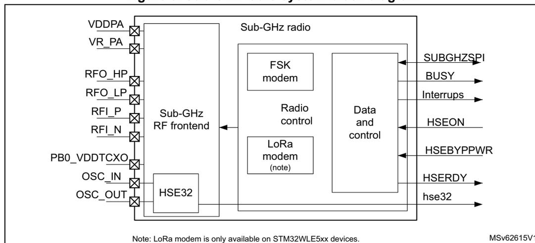
4.3.2 Sub-GHz radio signals
Table 18 gives the list of sub-GHz radio signals.
Table 18. Sub-GHz internal input/output signals
| Signal name | Signal type | Description |
|---|---|---|
| RFO_HP | RF output | Transmit high-power PA output |
| RFO_LP | RF output | Transmit low-power PA output |
| RFI_P | RF input | Receiver differential P input |
| RFI_N | RF input | Receiver differential N input |
| OSC_IN | Analog input | HSE32 oscillator input |
| OSC_OUT | Analog output | HSE32 oscillator output |
| VDDPA | Supply | Input supply for PA regulator |
| VR_PA | Supply | Regulated PA supply output |
| PB0_VDDTCXO | Supply | Regulated TCXO supply output |
| hse32 | Digital output | HSE32 clock signal to CPU |
| HSEON | Digital input | Enable HSE32 clock for CPU usage |
| HSEBYPWR | Digital input | Enable VDDTCXO regulator control |
Table 18. Sub-GHz internal input/output signals (continued)
| Signal name | Signal type | Description |
|---|---|---|
| HSERDY | Digital output | HSE32 clock ready indication |
| SUBGHZSPI | Digital in/output | Sub-GHz radio SPI interface |
| BUSY | Digital output | BUSY signal |
| Interrupts | Digital output | IRQ interrupts |
4.3.3 Transmitter
The transmit chain comprises the modulated output from the modem, that directly modulates the RF-PLL. An optional pre-filtering of the bit stream can be enabled to reduce the power in the adjacent channel also dependent on the selected modulation scheme. The modulated signal from the RF-PLL directly drives the high-power PA (HP PA) or low-power PA (LP PA).
Transmitter high output power
Transmit high output power up to + 22 dBm, is supported through the RFO_HP RF pin. The HP PA can be supplied from the PA regulator (REG PA) up to 3.1 V.
For this, the REG PA must be supplied directly from \( V_{DD} \) (on VDDSMPS pin), as shown in Figure 6.
Figure 6. High output power PA
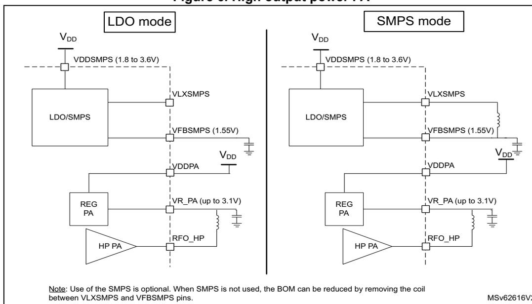
Note: Use of the SMPS is optional. When SMPS is not used, the BOM can be reduced by removing the coil between VLXSMPS and VFBSMPS pins.
Table 19 gives the maximum transmit output power versus the \( V_{DDPA} \) supply level.
Table 19. Sub-GHz radio transmit high output power
| \( V_{DDPA} \) supply (V) | Transmit output power (dBm) |
|---|---|
| 3.3 | + 22 |
| 2.7 | + 20 |
| 2.4 | + 19 |
| 1.8 | + 16 |
Transmitter low output power
The transmit low output power up to + 15 dBm, is supported through the RFO_LP pin. The LP PA can be supplied from the PA regulator (REG PA) up to 1.35 V. For this, the REG PA must be supplied from the regulated \( V_{FBSMPS} \) supply at 1.55 V, as shown in the figure below.
The output power range is programmable in 32 steps of ~1 dB. The power amplifier ramping timing is also programmable. This allows adaptation to meet radio regulation requirements.
Figure 7. Low output power PA
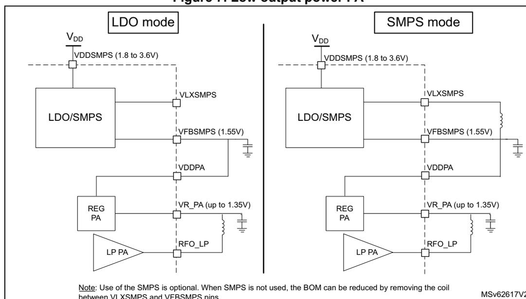
The diagram illustrates two power supply configurations for the Low Power Power Amplifier (LP PA):
- LDO mode: The LP PA is connected to the output of the REG PA (VR_PA), which is in turn connected to the output of the VFB SMPS (1.55V). The REG PA is connected to the VDDPA supply. The VFB SMPS is connected to the VLX SMPS (1.8 to 3.6V) supply.
- SMPS mode: The LP PA is connected to the output of the REG PA (VR_PA), which is in turn connected to the output of the VLX SMPS (1.8 to 3.6V) via a coil. The REG PA is connected to the VDDPA supply. The VLX SMPS is connected to the VDD supply.
Note: Use of the SMPS is optional. When SMPS is not used, the BOM can be reduced by removing the coil between VLXSMPS and VFBSMPS pins. MSV62617V2
4.3.4 Receiver
The receive chain comprises a differential low-noise amplifier (LNA), a down-converter to low-IF by mixer operation in quadrature configuration. The I and Q signals are low pass filtered and a \( \Sigma\Delta \) ADC converts them into the digital domain. In the digital modem, the signals are decimated, further down converted and channel filtered. The demodulation is done according to the selected modulation scheme.
The down mixing to low-IF is done by mixing the receive signal with the local RF-PLL located in the negative frequency, where \( -f_{lo} = -f_{rf} + f_{if} \) . (where \( f_{lo} \) is the local RF-PLL
frequency, \( f_{rf} \) is the received signal and \( f_{if} \) is the intermediate frequency). The wanted signal is located at \( f_{rf} = f_{lo} + f_{if} \) .
The receiver features automatic I and Q calibration, that improves image rejection. The calibration is done automatically at startup before using the receiver, and can be requested by command (see Image calibration for specific frequency bands for more details).
The receiver supports LoRa and (G)FSK modulations.
4.3.5 RF-PLL
The RF-PLL is used as the frequency synthesizer for the generation of the local oscillator frequency ( \( f_{lo} \) ) for both transmit and receive chains. The RF-PLL uses auto calibration and uses the 32 MHz HSE32 reference. The sub-GHz radio covers all continuous frequencies in the range between 150 to 960 MHz.
4.3.6 Intermediate frequencies
The sub-GHz radio receiver operates mostly in low-IF configuration, except for specific high-bandwidth settings.
Table 20. FSK mode intermediate frequencies
| Setting name | Bandwidth (kHz) | \( f_{if} \) (kHz) |
|---|---|---|
| RX_BW_467 | 467.0 | 250 |
| RX_BW_234 | 234.3 | |
| RX_BW_117 | 117.3 | |
| RX_BW_58 | 58.6 | |
| RX_BW_29 | 29.3 | |
| RX_BW_14 | 14.6 | |
| RX_BW_7 | 7.3 | |
| RX_BW_373 | 373.6 | 200 |
| RX_BW_187 | 187.2 | |
| RX_BW_93 | 93.8 | |
| RX_BW_46 | 46.9 | |
| RX_BW_23 | 23.4 | |
| RX_BW_11 | 11.7 | |
| RX_BW_5 | 5.8 | |
| RX_BW_312 | 312.0 | 167 |
| RX_BW_156 | 156.2 | |
| RX_BW_78 | 78.2 | |
| RX_BW_39 | 39.0 | |
| RX_BW_19 | 19.5 | |
| RX_BW_9 | 9.7 | |
| RX_BW_4 | 4.8 |
| Setting name | Bandwidth [kHz] | \( f_{if} \) [kHz] |
|---|---|---|
| LORA_BW_500 | 500 | 0 |
| LORA_BW_250 | 250 | 250 |
| LORA_BW_125 | 125 | |
| LORA_BW_62 | 62.5 | |
| LORA_BW_41 | 41.67 | 167 |
| LORA_BW_31 | 31.25 | 250 |
| LORA_BW_20 | 20.83 | 167 |
| LORA_BW_15 | 15.63 | 250 |
| LORA_BW_10 | 10.42 | 167 |
| LORA_BW_7 | 7.81 | 250 |
4.4 Sub-GHz radio clocks
4.4.1 Internal oscillators
The following sub-GHz radio dedicated internal RC oscillators are available:
- 64 kHz RC oscillator
- optionally used during the sub-GHz radio Sleep mode to wake up the transceiver when performing periodic or duty cycled operations
- used by the sub-GHz radio RTC for time based events
- 13 MHz RC oscillator, enabled for all sub-GHz radio SPI communication
The frequency of each sub-GHz radio internal oscillators is calibrated using the HSE32 clock at every sub-GHz radio transition from Deep-Sleep or Sleep-to-Standby, and after a sub-GHz radio reset. The calibration can also be done on demand by the command
Calibrate()
.
4.4.2 HSE32 reference clock
The high-precision 32 MHz frequency needed for the sub-GHz radio transmission and reception is taken from HSE32. The HSE32 clock can also be used by the MCU. The use of an external crystal (XTAL) or a temperature compensated crystal oscillator (TCXO) are supported. The used clock source is configured in the RCC (see Section 6.2.1: HSE32 clock with trimming for more details).
When using the HSE32 with a XTAL, the load capacitors are provided by the integrated capacitor banks that can be trimmed. The trimming is provided by SUBGHZ_HSEINTRIMR and SUBGHZ_HSEOUTRIMR registers. The load capacitances on OSC_IN and OSC_OUT can be trimmed separately. Software trimming must be applied after the sub-GHz radio entered Standby with HSE32 mode.
The TCXO regulator, integrated in the sub-GHz radio, can be used to supply an external temperature compensated crystal oscillator (TCXO). The regulated
\(
V_{DDTCXO}
\)
supply level is controlled through
set_TcxoMode()
command.
The sub-GHz radio, depending on the transmit output power (max + 22 dBm), can heat up the device. The heating depends on the used transmit output power and the device package. Careful PCB design using thermal heat dissipation techniques must be applied to avoid heat transfer to the HSE32 reference clock source. For the HSE32 frequency drift requirements related to the sub-GHz radio, see Section 4.5.1 .
4.5 Sub-GHz radio modems
The following modems are provided enabling the respective modulation and associated framing.
- • LoRa with the LoRa framing
- • FSK and MSK with a generic framing
- • BPSK with a BPSK framing
The modems and frame types are set by
Set_PacketType()
command. The current used modem and frame type can be obtained by
Get_PacketType()
command.
Once the modem and frame to be used are selected, modulation and packet parameters can be defined by
Set_ModulationParams()
and
Set_PacketParams()
commands.
The LoRa and (G)FSK (a) modems support both transmission and reception.
The (G)MSK and BPSK modems only supports transmission.
The framing determines how the bit stream is translated in packets and how data is stored in the data buffers. It performs operations such as whitening and CRC handling. The framing is configured using
Set_PacketParams()
command.
4.5.1 LoRa modem
The LoRa modem uses spread spectrum modulation and forward error correction techniques to increase the range and reliability of sub-GHz radio communication. The LoRa modem provides improved co-channel rejection.
The LoRa modulation can be optimized for a given application by
Set_ModulationParams()
command, allowing a trade off between link budget, interference immunity, spectral occupation and nominal data rate.
The following parameters can be optimized:
- • spreading factor (SF)
- • modulation bandwidth (BW)
- • error coding rate (CR)
- • low data rate optimization (LDRO)
The LoRa symbol rate ( \( R_s \) ) is defined as \( R_s = BW / 2^{SF} \)
The transmitted signal is a constant envelope signal. Equivalently, one chip is sent per second per Hz of bandwidth.
a. The (G)FSK modem can be used for (G)MSK modulation in Tx and Rx when setting the frequency deviation to a quarter of the bit rate.
Spreading factor (SF)
The LoRa spread spectrum modulation is performed by representing each data bit of the packet payload by multiple chips of information. The rate at which the spread information is sent, is referred to as the symbol rate ( \( R_s \) ). The ratio between the nominal data rate and the chip rate is the spreading factor (SF). It represents the number of symbols per data bit.
The spreading factor must be known in advance on both transmit and receive side of the link.
The resulting signal to noise ratio (SNR) required at the receiver input, is influenced by the spreading factor. This allows the increase of the receiver sensitivity, and so increase the link budget and range.
A higher spreading factor provides a better receiver sensitivity, more link budget and longer range at the expense of a longer transmission time (see the table below).
Table 22. Spreading factor, chips/symbol and LoRa SNR
| Spreading factor (SF) | 5 | 6 (1) | 7 (2) | 8 | 9 | 10 | 11 | 12 |
|---|---|---|---|---|---|---|---|---|
| \( 2^{SF} \) (chips/symbol) | 32 | 64 | 128 | 256 | 512 | 1024 | 2048 | 4096 |
| LoRa demodulator SNR (dB) | - 2.5 | - 5 | - 7 | - 9.5 | - 12 | - 14.5 | - 17 | - 19 |
- 1. The SF6 is not backward compatible with earlier LoRa devices.
- 2. Default value.
For SF5 and SF6, due to the higher symbol rate, the minimum preamble length needed to ensure correct detection and demodulation of the received signal is 12 symbols.
Bandwidth (BW)
An increase in signal bandwidth allows the use of a higher effective data rate and reduces the transmission time at the expense of a reduced sensitivity, less link budget and shorter range. The LoRa modem operates at a programmable bandwidth (BW) around a programmable RF frequency ( \( f_H \) ).
There are country dependent regulatory constraints on the permitted occupied bandwidth. The LoRa signal bandwidth refers to the double side bandwidth (DSB). The bandwidth selection range is given in the table below.
Table 23. LoRa bandwidth setting
| LoRa BW setting | 0 | 8 | 1 | 9 | 2 | 10 | 3 | 4 | 5 (1) | 6 (1) |
|---|---|---|---|---|---|---|---|---|---|---|
| Bandwidth (kHz) | 7.81 | 10.42 | 15.63 | 20.83 | 31.25 | 41.67 | 62.5 | 125 | 250 | 500 |
- 1. Bandwidth not available below a 400 MHz RF frequency.
Forward error correction coding rate (CR)
The sub-GHz radio communication reliability can be improved by performing forward error correction. This is particularly efficient in the presence of interference. The coding rate can be changed in response to channel condition. The coding rate information is included in the packet header for use by the receiver.
A higher coding rate provides better immunity to interference at the expense of longer transmission time. In normal conditions and factor of 4 / 5 provides the best trade off. In case of strong interference, a higher coding rate may be used.
The coding rate and overhead ratio is given in the table below.
Table 24. Coding rate and overhead ratio
| CR setting | 0 (1) | 1 | 2 (2) | 3 | 4 |
|---|---|---|---|---|---|
| Coding rate (data bits/total coded bits) | 4/4 | 4/5 | 4/6 | 4/7 | 4/8 |
| Overhead ratio | 1 | 1.25 | 1.5 | 1.75 | 2 |
1. No forward error correction.
2. Default value.
Low data rate optimization (LDRO)
For low data rates (typically high SF or low BW) and very long payloads (may last several seconds), the low data rate optimization (LDRO) can be enabled. This reduces the number of bits per symbol to the given SF minus 2, to allow the receiver to have a better tracking of the LoRa receive signal. Depending on the payload length, the low data rate optimization is usually recommended when the LoRa symbol time is equal or above 16.38 ms.
When using LoRa modulation, the total frequency drift over the packet time must be kept lower than Freq_drift_max:
When possible, enabling the low data rate optimization (Set_ModulationParams() command), relaxes the total frequency drift over the packet time by 16:
4.5.2 LoRa framing
The following types of LoRa packet formats are available:
- • explicit header mode packet: includes a short header that contains information about the number of payload bytes, coding rate and presence of CRC.
- • implicit header mode packet (no header)
The LoRa packet frames are illustrated in Figure 8 .
Figure 8. LoRa packet frames format
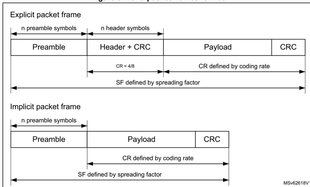
The diagram illustrates two LoRa packet frame formats: Explicit and Implicit.
Explicit packet frame:
- The frame consists of four fields: Preamble, Header + CRC, Payload, and CRC.
- The Preamble is labeled as "n preamble symbols".
- The Header + CRC is labeled as "n header symbols".
- The Header + CRC field has a coding rate of \( CR = 4/8 \) .
- The Payload field has a coding rate defined by the coding rate.
- The entire frame (Preamble + Header + CRC + Payload + CRC) has a spreading factor defined by the spreading factor (SF).
Implicit packet frame:
- The frame consists of three fields: Preamble, Payload, and CRC.
- The Preamble is labeled as "n preamble symbols".
- The Payload field has a coding rate defined by the coding rate.
- The entire frame (Preamble + Payload + CRC) has a spreading factor defined by the spreading factor (SF).
MSv62618V1
The LoRa packet frames start with a preamble that is used to synchronize the receiver with the received signal. By default, the packet is configured with a 12-symbol-long preamble sequence. The preamble length is programmable by
Set_PacketParams()
command. This allows the transmission of near arbitrarily long preamble sequences.
The receiver undertakes a preamble detection process that periodically restarts. For this reason, the preamble length at receiving side must be configured identical to the one at transmitting side. When the preamble length is not known at receiving side or when it varies, the maximum preamble length must be programmed at receiving side.
In the explicit packet format, the preamble is followed by a header with CRC, then followed by the payload and payload CRC.
In the implicit packet format, the preamble is directly followed by the payload and payload CRC.
The payload is a variable length field that contains the user data coded at the coding rate, either as specified in the explicit header or in the sub-GHz configuration when using implicit mode, by
Set_PacketParams()
and
Set_ModulationParams()
commands.
The payload can be followed by an optional payload CRC.
Explicit header mode
The default operation mode is the explicit header mode, where the header provides information on the payload. The header is transmitted using maximum forward error correction coding rate \( 4/8 \) . It is protected by its own header CRC to allow the receiver to discard a packet up on receiving an invalid header.
Implicit header mode
In certain operation modes where the payload coding rate and CRC presence are fixed or known in advance, it can be advantageous to reduce transmission time by invoking implicit header mode. In this mode, the header is not present in the packet frame. The payload length, forward error correction coding rate and presence of the payload CRC must be configured on both sides of the sub-GHz radio link.
LoRa time-on-air
The total transmission time of packet can be calculated as follows:
where PreambleSymbols is the number of preamble symbols programmed in
Set_PacketParams(PbLength)
.
The number of payload symbols can be calculated as follows:
where CEILING is the function that rounds up to the integer multiple of (4 + CR) immediately superior to the fractional first parameter.
The number of payload fractional symbols in Explicit mode can be calculated as follows:
The number of payload fractional symbols in Implicit mode can be calculated as follows:
where:
- • CRC = 0 (no CRC) or 1 (16-bit CRC)
- • CR = 0 to 4
- • PL = 1 to 255, user data payload length in number of bytes
- • SF = 7 to 12 spreading factor
LoRa data rates “raw data rate” and “real data rate” are defined as:
Channel activity detection (CAD)
The channel activity detection is used to detect the presence of a LoRa signal, by detecting a LoRa preamble or data symbols.
Once in channel activity detection mode, the band is scanned for a determined duration as set in
Set_CadParams()
command. If LoRa symbols are detected during this period, the channel activity detected IRQ is set.
The time needed to perform the channel activity detection depend on the LoRa modulation settings. For a given SF / BW, the typical CAD detection time can be selected to be 1, 2, 4, 8, or 16 symbols. The CAD duration time is further more extended with half a symbol.
4.5.3 FSK modem
The FSK modem provides a 2-FSK modulation over a range of data rates from 0.6 Kbit/s up to 300 Kbit/s. In receive mode, the bandwidth is automatically adjusted to match the selected data rate. In transmit mode, the frequency deviation is selected via the modulation
index. An optional Gaussian filter can be used. All modulation parameters are set using
Set_ModulationParams()
command.
The bit rate (or equivalent chip) is referenced to the HSE32 frequency and controlled by the BR parameter, defined as follows:
FSK modulation is performed inside the RF-PLL bandwidth, by changing the fractional divider. The high resolution of the RF-PLL allows very narrow frequency deviation. The frequency deviation parameter
\(
F_{dev}
\)
, is one of the parameters in
Set_ModulationParams()
.
\(
F_{dev}
\)
is defined as follows:
To ensure correct modulation, the following limit applies: \( (F_{dev} + BR/2) < BW \) .
The bandwidth must be chosen so that:
where \( \text{frequency error} = 2 \times HSE32_{FREQ} \text{ error} \)
The FSK modem offers several pulse shape options in the
PulseShape
parameter.
4.5.4 MSK modem
The MSK modem provides a 2-MSK modulation over a range of data rates from 0.1 Kbit/s up to 10 Kbit/s. This MSK modulation is only available in transmit mode. The modulation index is automatically adjusted to 0.5. An optional Gaussian filter can be used. All modulation parameters are set using
Set_ModulationParams()
command.
The bit rate (or equivalent chip) is referenced to the HSE32 frequency and controlled by the BR parameter, defined as follows:
4.5.5 Generic framing
The generic packet framing is used with the FSK and MSK modems.
The generic packet provides a conventional packet format for applications in proprietary NRZ coded, long range, low-energy communication links. The generic packet framing can be configured by
Set_PacketParams()
command and allows whitening based on pseudo random number generation, CRC operations and packet acknowledgment.
The following types of generic packet formats are available:
- • Variable length packet: including a short header (named length) that contains information about the number of payload bytes
- • Fixed length packet: no header
In both packet formats, the payload length is limited to 254 when the address filtering is activated.
The generic packet frames are illustrated in Figure 9 .
Figure 9. Generic packet frames format
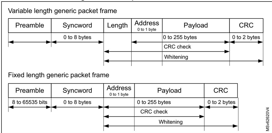
Variable length generic packet frame
| Preamble | Syncword | Length | Address 0 to 1 byte | Payload | CRC |
|---|---|---|---|---|---|
| 0 to 8 bytes | 0 to 255 bytes | 0 to 2 bytes | |||
| CRC check | |||||
| Whitening |
Fixed length generic packet frame
| Preamble | Syncword | Address 0 to 1 byte | Payload | CRC |
|---|---|---|---|---|
| 8 to 65535 bits | 0 to 8 bytes | 0 to 255 bytes | 0 to 2 bytes | |
| CRC check | ||||
| Whitening |
MSv62620V4
- 1. The payload length can be extended beyond 255 bytes. Refer to Section 4.6: Sub-GHz radio data buffer for more details.
The generic packet frames start with a preamble that is used to synchronize the receiver with the received signal. The preamble length is programmable by
Set_PacketParams()
command.
The receiver undertakes a preamble detection process that periodically restarts. For this reason, the preamble length at the receiving side must be configured identical to the one of the transmitting side. When the preamble length is not known at receiving side or when it can vary, the maximum preamble length must be programmed at receiving side.
The preamble is followed by a syncword field with programmable length in
Set_PacketParams()
command.
The address is optional and can be used for a unicast when several devices share the same syncword.
In the variable length generic packet format, the syncword is followed by the length of the payload (If the Address field is present then Length must include this additional byte), followed by the payload and payload CRC.
In the fixed length generic packet format, the syncword is directly followed by the payload and payload CRC.
The payload is a variable length field that contains the user data either as specified in the variable length generic packet or in the sub-GHz radio configuration when using fixed length generic packet by
Set_PacketParams()
.
The payload can be followed by an optional payload CRC with programmable length in
Set_PacketParams()
command.
Endianness of the frame is MSB first.
Variable length generic packet mode
When the packet is of uncertain or variable length, the information on the payload length must be transmitted within the packet. For this, a header with the payload length information is transmitted after the syncword.
Fixed length generic packet mode
In certain operation modes where the payload length is fixed or known in advance, it may be advantageous to reduce transmission time by invoking fixed length generic packet mode. In this mode, the header is not present in the packet frame and the payload length must be configured on both sides of the sub-GHz radio link.
Node or broadcast address
The node or broadcast address are not considered part of the payload. They are added automatically when enabled by
Set_PacketParams()
command. Adding these fields allows the user to perform additional packet filtering at the header level.
Whitening
Whitening is based on a 9-bit LFSR and used to whiten the payload and, when present, the header and CRC. Whitening limits a sequence of consecutive 1 or 0 bit to nine. The whitening polynomial is
\(
x^9 + x^5 + 1
\)
, and can be initialized with the whitening initial value in
WHITEINI[8:0]
.
CRC
CRC computation can be configured for polynomial and initial value, and allows inversion. Configuration is done through
Set_PacketParams()
command.
The flexible CRC configuration allows any standard CRC or proprietary CRC to be generated and checked, for example:
- • IBM CRC configuration
- – CRC polynomial 0x8005
- – CRC initial value 0xFFFF
- – 2-byte length CRC
- • CCIT CRC configuration
- – CRC polynomial 0x1021
- – CRC initial value 0x1D0F
- – 2-byte length inverted CRC
4.5.6 BPSK modem
The BPSK modem provides a BPSK modulation for data rates of 100 and 600 bit/s. BPSK modulation is only available in transmit mode. The modulation offers a raise-cosine pulse shape filter with a BT of 0.5. The BPSK modulator can be changed into DBPSK modulation by some host pre-processing on the data to be transmitted.
All modulation parameters are set by
Set_ModulationParams()
command.
The bit rate (or equivalent chip) is controlled by
Br
parameter, defined as follows:
4.5.7 BPSK framing
The BPSK packet framing is used with the BPSK modem. The BPSK packet framing can be configured by
Set_PacketParams()
command and allows the total frame length definition. The full packet (preamble, synch word, device id to CRC) must be provided in the transmit data buffer.
4.6 Sub-GHz radio data buffer
The sub-GHz radio uses a 256-byte RAM data buffer that is accessible by the CPU through the SUBGHZSPI interface in all sub-GHz radio operating modes except Sleep and Deep-Sleep. The RAM data buffer is cleared in Deep-Sleep mode, optionally retained in Sleep mode and always retained in all other modes. In Sleep and Deep-Sleep modes, the
TxBaseAddr
and
RxBaseAddr
values are lost. In order to retrieve data after Sleep mode retention, the default values must be used (
TxBaseAddr = 0x80
and
RxBaseAddr = 0x00
), or
RxPayloadLength
and
RxBufferPointer
must be stored in the CPU memory.
On die revision Y and later, the
PayloadLength
can be updated during transmission. This capability allows the support of long packets.
On previous die revisions, the
PayloadLength
is fixed (latched in the radio) after a
SetTx()
command.
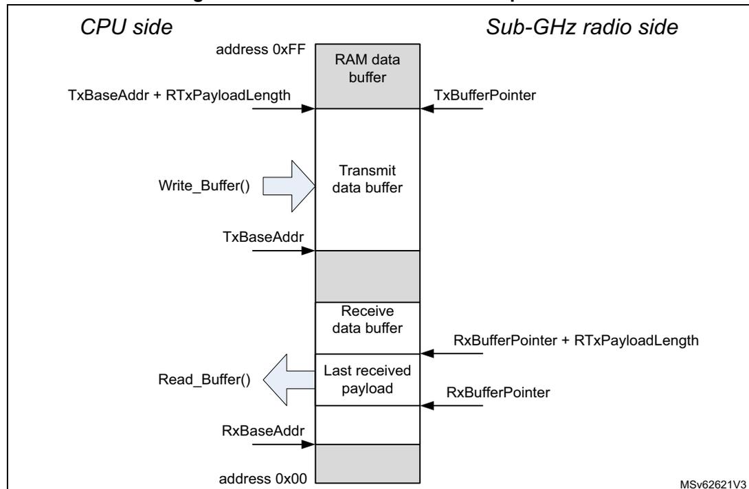
The RAM data buffers are fully configurable. They allow access to the transmit data buffer and the last receive data buffer. The RAM data buffer organization is depicted in the figure below.
Figure 10. Sub-GHz RAM data buffer operation
  graph TD
    subgraph CPU_Side [CPU side]
      direction TB
      A1[TxBaseAddr + RTxPayloadLength] --> B1
      B2[Write_Buffer] -- arrow --> B1
      C1[TxBaseAddr] --> B1
      D1[Read_Buffer] -- arrow --> E1
      F1[RxBaseAddr] --> E1
    end

    subgraph RAM_Buffer [RAM data buffer]
      direction TB
      Top[address 0xFF] --- G[RAM data buffer]
      G --- H[Transmit data buffer]
      H --- I[Receive data buffer]
      I --- J[Last received payload]
      J --- Bottom[address 0x00]
    end

    subgraph Radio_Side [Sub-GHz radio side]
      direction TB
      K1[TxBufferPointer] --> H
      L1[RxBufferPointer + RTxPayloadLength] --> I
      M1[RxBufferPointer] --> J
    end
The diagram illustrates the organization of the RAM data buffer (0x00 to 0xFF). On the CPU side,
Write_Buffer()
interacts with the Transmit data buffer (bounded by
TxBaseAddr
), and
Read_Buffer()
interacts with the Last received payload (starting at
RxBaseAddr
). On the Radio side,
TxBufferPointer
points into the Transmit buffer, while
RxBufferPointer
and
RxBufferPointer + RTxPayloadLength
define the boundaries of the received data.
The RAM data buffer is accessed by
Write_Buffer()
and
Read_Buffer()
commands. The offset parameter defines the address in the SRAM data buffer. To read the first byte
from the receive data buffer, the offset must be set to the RxBufferPointer value. To write to the first byte in the transmit data buffer, the offset must be set to the TxBaseAddr value.
The RAM data buffer has a circular nature: any address increment exceeding 0xFF wraps around to address 0x00.
4.6.1 Receive data buffer operation
In receive mode, RxBaseAddr, configured through
Set_BufferBaseAddress()
, determines the receive buffer offset in the sub-GHz radio RAM. RxBaseAddr can be set anywhere within the RAM data buffer. If needed, the whole 256-byte RAM data buffer can be used.
For the first received packet, RxBufferPointer is set to RxBaseAddr. The first byte of the first received packet payload data is written at the RxBufferPointer address. The last byte of the received packet payload data is written at the address determined by RxBufferPointer + RxPayloadLength. RxBufferPointer and RxPayloadLength can be read by
Get_RxBufferStatus()
command.
In single receive and listening modes, RxBufferPointer is automatically initialized to RxBaseAddr for each new reception when the sub-GHz radio enters RX mode.
In continuous receive mode, RxBufferPointer is continuously incremented from the position at which it was left by the previous received packet. In this mode, subsequent received packets are stored continuous in the RAM data buffer.
Caution: If the amount of received data exceeds the defined receive buffer size, other data in the RAM are overwritten.
Receive data are written to the receive data buffer regardless of the received CRC status. When the received CRC fails, post processing on the incorrectly received data can still be performed by the CPU.
Caution: When the received packet length exceeds the area allocated to the receive data buffer, it may overwrite the transmit data buffer area in the RAM data buffer.
4.6.2 Transmit data buffer operation
In transmit mode, TxBaseAddr determines the transmit buffer offset in the sub-GHz radio RAM. For each transmission, when the sub-GHz radio enters TX mode, TxBufferPointer is automatically initialized to TxBaseAddr. Each time a payload byte is transmitted, TxBufferPointer is incremented until all bytes, according to the PayloadLength set by the
Set_PacketParams()
command, are transmitted.
4.7 Sub-GHz radio operating modes
After a sub-GHz radio reset, a startup phase is initiated. As BUSY is active during this phase, commands cannot be accepted. When supply and clock are available to the sub-GHz radio, BUSY is deactivated and the CPU can take control.
The sub-GHz radio provides the following operating modes:
- •
Sleep mode
- – Deep-Sleep: all sub-GHz radio clocks are turned off and data memory is lost
- – RC 13 MHz clock turned off
- – RC 64 kHz and timers can be kept running (optional)
- – Optional registers and data memory retained
- •
Calibration mode
- – intermediate mode between Deep-Sleep or Sleep, and Standby
- – used to calibrate the sub-GHz radio RC 64 kHz, sub-GHz radio RC 13 MHz, RF-PLL, RF-ADC and image
- •
Standby mode
- – sub-GHz radio clocked by its internal RC 13 MHz clock
- – HSE32 clock can be kept running (optional)
- – data memory retained
- •
Active mode (FS, TX, RX)
- – Frequency synthesis (FS) mode: RF-PLL switched on
- – Transmit (TX) mode: the power amplifier (PA) ramped and data transmitted from the data buffer according the selected modulation scheme
- – Receive (RX) mode: sub-GHz radio looking for incoming data packets
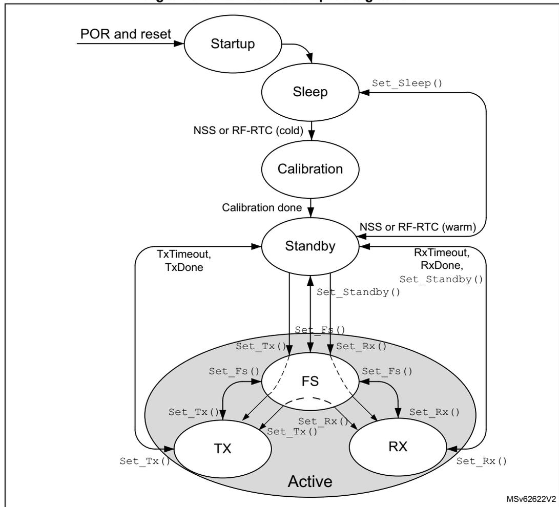
The sub-GHz radio operating modes are shown in the figure below.
Figure 11. Sub-GHz radio operating modes
    graph TD
      POR[POR and reset] --> Startup((Startup))
      Startup --> Sleep((Sleep))
      Sleep -- "Set_Sleep()" --> Sleep
      Sleep -- "NSS or RF-RTC (cold)" --> Calibration((Calibration))
      Calibration -- "Calibration done" --> Standby((Standby))
      Standby -- "NSS or RF-RTC (warm)" --> Sleep
      Standby -- "TxTimeout, TxDone" --> Standby
      Standby -- "RxTimeout, RxDone, Set_Standby()" --> Standby
      Standby -- "Set_Standby()" --> Standby
      Standby -- "Set_Fs()" --> FS((FS))
      Standby -- "Set_Tx()" --> TX((TX))
      Standby -- "Set_Rx()" --> RX((RX))

      subgraph Active
        FS
        TX
        RX
      end

      FS -- "Set_Fs()" --> FS
      FS -- "Set_Tx()" --> TX
      FS -- "Set_Rx()" --> RX

      TX -- "Set_Tx()" --> TX
      TX -- "Set_Rx()" --> RX
      TX -- "Set_Fs()" --> FS

      RX -- "Set_Rx()" --> RX
      RX -- "Set_Tx()" --> TX
      RX -- "Set_Fs()" --> FS
The diagram illustrates the operating modes of the sub-GHz radio. It starts with 'POR and reset' leading to 'Startup', which then transitions to 'Sleep'. From 'Sleep', the radio can return to 'Sleep' via 'Set_Sleep()' or move to 'Calibration' if 'NSS or RF-RTC (cold)' is triggered. 'Calibration' leads to 'Standby' upon completion. From 'Standby', the radio can return to 'Sleep' via 'NSS or RF-RTC (warm)', stay in 'Standby' due to 'TxTimeout, TxDone' or 'RxTimeout, RxDone, Set_Standby()', or enter 'Active' mode via 'Set_Standby()'. 'Active' mode includes 'FS' (Frequency Synthesis), 'TX' (Transmit), and 'RX' (Receive) states. Transitions between these active states are controlled by 'Set_Fs()', 'Set_Tx()', and 'Set_Rx()' functions. The diagram is labeled 'MSV62622V2' in the bottom right corner.
4.7.1 Startup mode
At POR or after a sub-GHz radio reset, the Startup mode is entered. BUSY is set. When internal supply and clocks become available, the sub-GHz radio enters Sleep mode.
4.7.2 Sleep mode
In Sleep mode, only the sub-GHz radio startup and Sleep control is operational and the configuration is lost. BUSY is set. Optionally, configuration registers and memories may be kept in retention. The RC 64 kHz and sub-GHz RTC may be kept running.
The Sleep mode provides the following sub-mode and options:
- • Deep-Sleep mode: all sub-GHz radio function off, controlled by
set_Sleep()command - • Sleep with the sub-GHz radio RC 64 kHz kept on: configuration registers can be retained as configured by
Set_Sleep()command - • Sleep with the data RAM retained, controlled by
Set_Sleep()command
Following a POR sub-GHz radio reset, the Deep-Sleep mode is entered from Startup mode. Sleep mode can be entered from Standby mode by
Set_Sleep()
command.
Caution:
After
Set_Sleep()
command, the sub-GHz radio cannot receive any SPI commands. The user must guarantee that the sub-GHz radio SPI NSS is not set low during 500 µs.
Exit Sleep mode can be done:
- • on a firmware request via the sub-GHz radio SPI NSS signal (keeping sub-GHz radio SPI NSS low for at least 20 µs)
- • on a request from the sub-GHz radio RTC timer generating an end-of-count event (corresponding to duty cycled operation)
When the sub-GHz radio configuration registers are retained, a warm start is performed when exiting Sleep mode. During a warm start, the configuration registers are restored with their retained value and the Calibration state is skipped.
4.7.3 Calibration mode
On a cold start, when transitioning from Deep-Sleep or Sleep mode to Standby mode, the intermediate Calibration mode is entered. In Calibration mode, BUSY is set to indicate that the sub-GHz radio is busy and cannot accept any SPI command.
The calibration phase consists of the following operations:
- • sub-GHz radio RC 64 kHz frequency calibration
- • sub-GHz radio RC 13 MHz frequency calibration
- • RF-PLL modulation path calibration
- • RF-ADC calibration
- • image calibration
The total calibration time is 1.6 ms. All calibration results are stored in data RAM.
When the data RAM is retained in Sleep mode, the sub-GHz radio retrieves the calibration data and then transitions to Standby mode without repeating the calibration phase.
Once the calibration is finished, BUSY is deactivated and the sub-GHz radio enters Standby with RC 13 MHz mode.
When in Standby mode, the calibration of different blocks can be requested by
Calibrate()
command.
Image calibration for specific frequency bands
The image calibration is performed as part of the calibration process, by default in the band 902 - 928 MHz. The image calibration can furthermore be requested in any band by
CalibrateImage()
command.
Image calibration must be redone when the RF frequency is changed significantly and when the temperature changes more than 20 °C.
4.7.4 Standby mode
The Standby mode is entered from the Calibration mode and can furthermore be entered by
Set_Standby()
command.
In Standby mode, BUSY is cleared. The software must configure the sub-GHz radio for FS, TX, RX or Sleep mode. By default, in Standby mode, the sub-GHz radio is clocked by the sub-GHz RC 13 MHz. For time critical applications, HSE32 can be turned on. The use of RC 13 MHz or HSE32 is selected by
Set_Standby()
command.
If the SMPS is used during the sub-GHz transmission or reception, SMPS must be enabled in the Standby with RC 13 MHz mode. The SMPS is selected by
Set_RegulatorMode()
command. When selected, the SMPS is enabled automatically when entering the Standby with HSE32 mode. If the SMPS has been enabled by the CPU with
PWR_CR5.SMPSSEN
, the SMPS remains enabled in all sub-GHz radio operating modes including transmission and reception.
4.7.5 Frequency synthesis mode (FS)
When entering FS mode, BUSY is set. In FS mode, the RF-PLL is activated. Once RF-PLL is locked, BUSY goes low. The sub-GHz radio may be requested to enter this mode by
Set_Fs()
.
Due to the low-IF architecture, the transmit and receive RF-PLL frequencies are different. The receive RF-PLL frequency is equal to the transmit frequency minus the intermediate frequency offset.
4.7.6 Transmit mode (TX)
The TX mode can be requested to be entered from Standby mode. In this case, the sub-GHz radio enters first FS mode to lock the RF-PLL, and subsequently TX mode.
In TX mode after ramping-up the power amplifier (PA), data from the data buffer is transmitted. The sub-GHz radio operates in one of the following transmit modes:
- • single transmit mode
- • single transmit with timeout mode: timeout used as safety, when the transmit is aborted or does not succeed. The timeout informs the software of such events.
The sub-GHz radio returns automatically to Standby mode after the last data bit of the packet is transmitted or after the timeout expires.
TX mode entry is requested by
Set_Tx()
command.
When entering TX mode, BUSY is set. In TX mode, BUSY is cleared when the PA ramped up and preamble transmission starts.
PA ramping
The PA ramping time can be selected while setting the output power, by
Set_TxParams()
.
4.7.7 Receive mode (RX)
The RX mode can be requested to be entered from Standby mode. In this case, the sub-GHz radio enters first FS mode to lock the RF-PLL, and subsequently RX mode.
In RX mode, LNA, RF-PLL and selected modem are enabled. The receive mode provides the following operating modes:
- • Continuous mode: The sub-GHz radio remains in RX mode and waits for incoming packets reception until the software terminates RX mode.
- • Single mode: The sub-GHz radio remains in RX mode until a packet reception and enters automatically Standby mode after.
- • Single with timeout mode: The sub-GHz radio remains in RX mode until a packet reception or until the timeout expires, and enters automatically Standby mode after.
- • Listening mode: The sub-GHz radio repeatedly switches between RX single with timeout mode and Sleep mode, until an IRQ is triggered.
RX mode entry is requested by
Set_Rx()
command.
When entering RX mode, BUSY is set. In RX mode, BUSY is cleared when the receiver is ready to receive data.
The receiver provides a power-saving mode at the expense of reduced sensitivity. The receiver power-saving mode is controlled by the SUBGHZ_RXGAINR register.
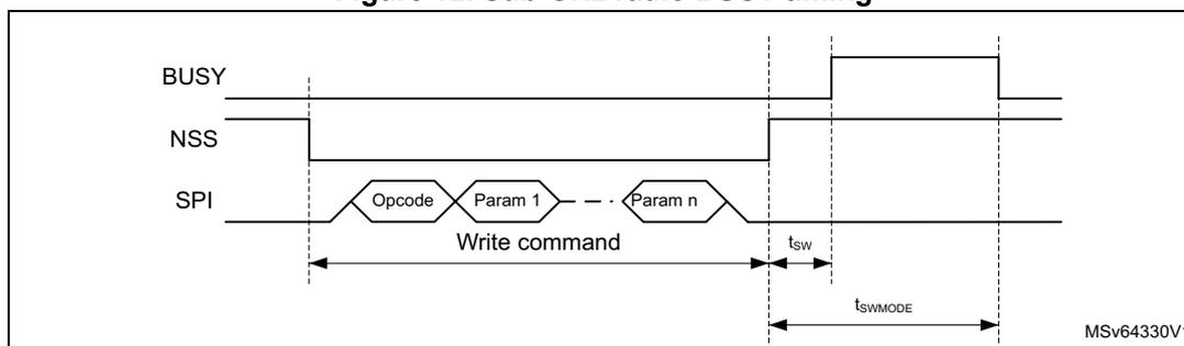
4.7.8 Active mode switching time
At each transaction with the sub-GHz radio (register read/write operation or mode switching), BUSY is set during the transaction and while the sub-GHz radio is processing the command. BUSY is cleared once the command processing is finished or reached a stable operating mode, and the sub-GHz radio is ready to receive a new command.
All write commands activate BUSY. For read commands, BUSY remains low.
Switching time ( \( t_{SWMODE} \) ) is defined as the time to process the command or reach a stable operating mode, starting from the sub-GHz radio SPI NSS rising edge, ending the SPI command transaction, until BUSY goes inactive. There is a small delay ( \( t_{SW} \) ) between the sub-GHz radio SPI NSS rising edge, ending the SPI command transaction, and when BUSY is set. The maximum time for \( t_{SW} \) is 600 ns.
BUSY timing is shown in the figure below.
Figure 12. Sub-GHz radio BUSY timing
For the different mode transitions, typical busy timing values are given in the table below.
Table 25. Operation mode transition BUSY switching time
| Mode transition | SPI command (sub-GHz radio event) | t swMODE typical (μs) |
|---|---|---|
| Sleep-to-Standby (no data retention) | SPI NSS low 20 μs | 3500 |
| Sleep-to-Standby (with data retention) | SPI NSS low 20 μs (RTC end-of-count) | 340 |
| Standby-to-Standby with HSE32 | Set_Standby() | 31 |
| Standby (HSE32 off)-to-FS (1) | Set_Fs() | 50 |
| Standby (HSE32 off)-to-TX (2) | all Set_Tx() | 126 |
| Standby (HSE32 off)-to-RX (3) | Set_Rx(), Set_Cad() | 83 |
| Standby (HSE32 on)-to-FS (1) | Set_Fs() | 40 |
| Standby (HSE32 on)-to-TX (2) | all Set_Tx() | 105 |
| Standby (HSE32 on)-to-RX (3) | Set_Rx(), Set_Cad() | 62 |
| FS-to-TX (2) | all Set_Tx() | 76 |
| FS-to-RX (3) | Set_Rx(), Set_Cad() | 41 |
- 1. When entering FS mode, BUSY is cleared to 0 when RF-PLL is locked.
- 2. When entering TX mode, BUSY is cleared to 0 when the PA ramps up and the transmission of preamble starts.
- 3. When entering RX mode, BUSY is cleared to 0 when the receiver is ready to receive data.
4.8 Sub-GHz radio SPI interface
The sub-GHz radio SPI slave interface gives access to the sub-GHz radio configuration, registers and buffer memory, through SPI commands. It is connected to the SUBGHZSPI master interface peripheral on the CPU bus matrix.
For a write access, an opcode byte is sent followed by sending the command parameter bytes.
For a read access, an opcode byte is sent followed by receiving data bytes.
For each access, the sub-GHz radio SPI NSS goes low at the start of the transfer and is set high at the end, after all bytes have been transferred.
The following transaction types are supported:
- • configuration transaction: provides the CPU with a direct access to control registers. Used to write or read sub-GHz radio configuration registers or buffer memory.
- • command transaction: requires more complex, non-atomic operations such as packet transmission and reception or operating mode changes
BUSY is used to indicate the status of the sub-GHz radio and its ability (or not) to receive a SPI transaction. Prior to issuing a new SPI transaction, the CPU must check the BUSY status to make sure a new transaction can be received by the sub-GHz radio.
4.8.1 Sub-GHz radio command structure
The SPI command structure consists of an opcode and parameters when writing data to the sub-GHz radio, and consists of a status when reading data.
In case of a write command that does not require any parameters, the CPU sent only an opcode over the sub-GHz radio SPI interface.
In case of a write command that requires parameters, the opcode is followed immediately by the parameter bytes. All parameters must be sent before the sub-GHz radio SPI NSS rising edge, that terminates the command.
In case of a read command, the opcode is followed immediately by the status bytes. All status must be received before the sub-GHz radio SPI NSS rising edge, that terminates the command.
Command structure values are given in the table below.
Table 26. Command structure
| Command type | Byte 0 | Byte 1:n |
|---|---|---|
| Write command without parameter | Opcode | Not applicable |
| Write command with parameters | Opcode | Parameters |
| Read command | Opcode | data |
4.8.2 Register and buffer access commands
Write_Register() command
Write_Register(Addr, Data0, Data1, to Datan) allows a block of bytes to be written in a contiguous memory area, starting from the specified address. The address is auto incremented after each byte.
| 0 | 1 | 2 | 3 | ... | n+3 | |
|---|---|---|---|---|---|---|
| Opcode | Addr[15:0] | Data0[7:0] | ... | Datan[7:0] | ||
| w | w | w | w | w | ||
byte 0 bits 7:0 Opcode: 0x0D
bytes 2:1 bits 15:0 Addr[15:0]: first write address
byte 3 bits 7:0 Data0[7:0] : data to write to first address
... ..
byte n+3 bits 7:0 Datan[7:0] : data to write to address + n (n = number of bytes to write)
Read_Register() command
Read_Register(Addr, Status, Data0, Data1, to Datan) allows a block of bytes to be read in a contiguous memory area starting from the specified address. The address is auto incremented after each byte.
| 0 | 1 | 2 | 3 | 4 | ... | n+4 |
|---|---|---|---|---|---|---|
| Opcode | Addr[15:0] | Status[7:0] | Data0[7:0] | ... | Datan[7:0] | |
| w | w | w | r | r | r | r |
byte 0 bits 7:0 Opcode : 0x1D
bytes 2:1 bits 15:0 Addr[15:0] : first read address
byte 3 bits 7:0 Status[7:0] : see Get_Status() command
byte 4 bits 7:0 Data0[7:0] : data read from first address
... ..
byte n+4 bits 7:0 Datan[7:0] : data read from address + n (n = number of bytes to read)
Write_Buffer() command
Write_Buffer(Offset, Data0, Data1, to Datan) allows transmit packet payload data to be written to a contiguous data memory area, starting from the specified offset. The offset is auto incremented after each byte. When the offset exceeds the value 255, it is wrapped around to 0 (providing a 256-byte circular buffer).
| 0 | 1 | 2 | ... | n+2 |
|---|---|---|---|---|
| Opcode | Offset[7:0] | Data0[7:0] | ... | Datan[7:0] |
| w | w | w | w | w |
byte 0 bits 7:0 Opcode : 0x0E
byte 1 bits 7:0 Offset[7:0] : first write address offset
byte 2 bits 7:0 Data0[7:0] : data to write to offset address
... ..
byte n+2 bits 7:0 Datan[7:0] : data to write to offset address + n (n = number of bytes to write)
Read_Buffer() command
Read_Buffer(Offset, Status, Data0, Data1, to Datan) allows receive packet payload data to be read from a contiguous data memory area, starting from the specified
offset. The offset is auto incremented after each byte. When the offset exceeds the value 255, it is wrapped around to 0 (providing a 256 byte circular buffer).
| 0 | 1 | 2 | 3 | ... | n+3 |
|---|---|---|---|---|---|
| Opcode | Offset[7:0] | Status[7:0] | Data0[7:0] | ... | Datan[7:0] |
| w | w | r | r | r | r |
byte 0 bits 7:0 Opcode: 0x1E
byte 1 bits 7:0 Offset[7:0]: first read address offset
byte 2 bits 7:0 Status[7:0]: see Get_Status() command
byte 3 bits 7:0 Data0[7:0]: data read from offset address
...
byte n+3 bits 7:0 Datan[7:0]: data read from offset address + n (n = number of bytes to read)
4.8.3 Operating mode commands
Set_Sleep() command
Set_Sleep(SleepCfg)
is used to set the sub-GHz radio in Sleep mode. This command is only accepted in Standby mode. The
SleepCfg
parameter allows some optional functions to be maintained in Sleep mode.
| 0 | 1 |
|---|---|
| Opcode | SleepCfg |
| w | w |
byte 0 bits 7:0 Opcode: 0x84
byte 1 bits 7:3 Reserved, must be kept at reset value.
bit 2 SleepCfg_Start: Sub-GHz radio startup selection
0: cold startup when exiting Sleep mode, configuration registers reset
1: warm startup when exiting Sleep mode, configuration registers kept in retention
Note: Only the configuration of the activated modem, before going to Sleep mode, is retained. The configuration of the other modes is lost and must be re-configured when exiting Sleep mode.
bit 1 Reserved, must be kept at reset value.
bit 0 SleepCfg_RTCEn: Sub-GHz radio RTC wake-up enable
0: Sub-GHz radio RTC wake-up disabled
1: Sub-GHz radio RTC wake-up enabled
Set_Standby() command
Set_Standby(StandbyCfg)
is used to set the sub-GHz radio in Standby mode. The
StandbyCfg
parameter allows some optional functions to be selected in Standby mode.
| 0 | 1 |
|---|---|
| Opcode | StandbyCfg |
| w | w |
byte 0 bits 7:0 Opcode: 0x80
byte 1 bits 7:1 Reserved, must be kept at reset value.
bit 0 StandbyCfg_StandbyClk: set clock in Standby mode
0: RC 13 MHz used in Standby mode
1: HSE32 used in Standby mode (Standby with HSE32)
Set_Fs() command
Set_Fs()
is used to set the sub-GHz radio in FS mode. This command allows the RF-PLL test.
| 0 |
|---|
| Opcode |
| w |
byte 0 bits 7:0 Opcode: 0xC1
The RF-PLL frequency must be set by
Set_RfFrequency()
command prior sending
Set_Fs()
.
Set_Tx() command
Set_Tx(Timeout)
is used to set the sub-GHz radio in TX mode.
| 0 | 1 | 2 | 3 |
|---|---|---|---|
| Opcode | Timeout[23:0] | ||
| w | w | w | w |
byte 0 bits 7:0 Opcode: 0x83
bytes 3:1 bits 23:0 Timeout[23:0]: Transmit packet timeout
0x000000: Timeout disabled
0x000001 - 0xFFFFFF: Timeout enabled, resolution 15.625 µs
Time-out duration is computed as follows:
Time-out duration = Timeout x 15.625 µs (maximum time-out duration = 262.14 s)
When
Set_Tx(Timeout)
is sent in Standby or Receive mode, the sub-GHz radio passes through the FS mode (no need to send
Set_Fs()
). In this case, the RF-PLL frequency must be set by
Set_RfFrequency()
prior sending
Set_Tx(Timeout)
.
Set_Rx() command
Set_Rx(Timeout)
is used to set the sub-GHz radio in Receive mode.
| 0 | 1 | 2 | 3 |
|---|---|---|---|
| Opcode | Timeout[23:0] | ||
| w | w | w | w |
byte 0 bits 7:0 Opcode: 0x82
bytes 3:1 bits 23:0 Timeout[23:0]: Transmit packet timeout
0x000000: timeout disabled
0x000001 - 0xFFFFFE: timeout enabled, single packet receive mode, resolution 15.625 µs
0xFFFFFFFF: timeout disabled, continuous receive mode
Time-out duration is computed by the following formula:
When
Set_Rx(Timeout)
is sent in Standby mode or Transmit mode, the sub-GHz radio passes through the FS mode (no need to send
Set_Fs()
). In this case, the RF-PLL frequency must be set by
Set_RfFrequency()
prior sending
Set_Rx(Timeout)
.
Set_StopRxTimerOnPreamble() command
Set_StopRxTimerOnPreamble(RxTimeoutStop)
allows the selection of the receiver event on which the receiver timeout timer (in
Set_Rx()
), is stopped.
| 0 | 1 |
|---|---|
| Opcode | RxTimeoutStop |
| w | w |
byte 0 bits 7:0 Opcode: 0x9F
byte 1 bits 7:1 Reserved, must be kept at reset value.
bit 0 RxTimeoutStop: receiver timeout timer stop event selection
0: receive timeout stopped on synchronization word detection in generic packet mode or header detection in LoRa packet mode
1: receive timeout stopped on preamble detection
Caution: When the receiver timeout is selected to be stopped on preamble detection, the sub-GHz radio remains in Receive mode until a packet is received. A false preamble detection may cause the sub-GHz radio to remain in Receive mode for an unexpected long period, until stopped by a mode configuration command.
Set_RxDutyCycle() command
Set_RxDutyCycle(RxPeriod, SleepPeriod)
is used to set the sub-GHz radio receiver in listening mode, regularly looking for new packets. This command must be sent in Standby mode. This command is only functional with FSK and LoRa packet type.
The following steps are performed:
- 1. Save sub-GHz radio configuration.
- 2. Enter Receive mode and listen for a preamble for the specified RxPeriod period.
- 3. Upon the detection of a preamble, the RxPeriod timeout is stopped and restarted with the value \( 2 \times \text{RxPeriod} + \text{SleepPeriod} \) . During this new period, the sub-GHz radio looks for the detection of a synchronization word when in (G)FSK modulation mode, or a header when in LoRa modulation mode.
- 4. If no packet is received during the listen period defined by \( 2 \times \text{RxPeriod} + \text{SleepPeriod} \) , the Sleep mode is entered for a duration of SleepPeriod. At the end of the receive period, the sub-GHz radio takes some time to save the context before starting the sleep period.
- 5. After the sleep period, a new listening period is automatically started. The sub-GHz radio restores the sub-GHz radio configuration and continuous with step 2.
The listening mode is terminated in one of the following cases:
- • if a packet is received during the listening period: the sub-GHz radio issues a RxDone interrupt and enters Standby mode.
- • if SetStandby() is sent during the listening period or after the sub-GHz has been requested to exit Sleep mode by sub-GHz radio SPI NSS
| 0 | 1 | 2 | 3 | 4 | 5 | 6 |
|---|---|---|---|---|---|---|
| Opcode | RxPeriod[23:0] | SleepPeriod[23:0] | ||||
| w | w | w | w | w | w | w |
byte 0 bits 7:0 Opcode: 0x94
bytes 3:1 bits 23:0 RxPeriod[23:0]: Receive duration
0x000000: Receiver duration disabled, receiver remaining active until a packet is detected
0x000001 - 0xFFFFF: Receive duration, resolution 15.625 \( \mu \) s
bytes 6:4 bits 23:0 SleepPeriod[23:0]: Sleep duration, resolution 15.625 \( \mu \) s
Receive period duration is computed as follows:
\( \text{Receive period duration} = \text{RxPeriod} \times 15.625 \mu\text{s} \) (max receiver duration = 262.14 s)
Sleep period duration is computed by the following formula:
\( \text{Sleep period duration} = \text{SleepPeriod} \times 15.625 \mu\text{s} \) (max sleep duration = 262.14 s)
For correct operation, the following must be respected:
- • (G)FSK modulation: \( T_{\text{preamble}} + T_{\text{syncword}} \leq 2 \times \text{RxPeriod} + \text{SleepPeriod} \)
- • LoRa modulation: \( T_{\text{preamble}} + T_{\text{header}} \leq 2 \times \text{RxPeriod} + \text{SleepPeriod} \)
Figure 13. Receiver listening mode timing
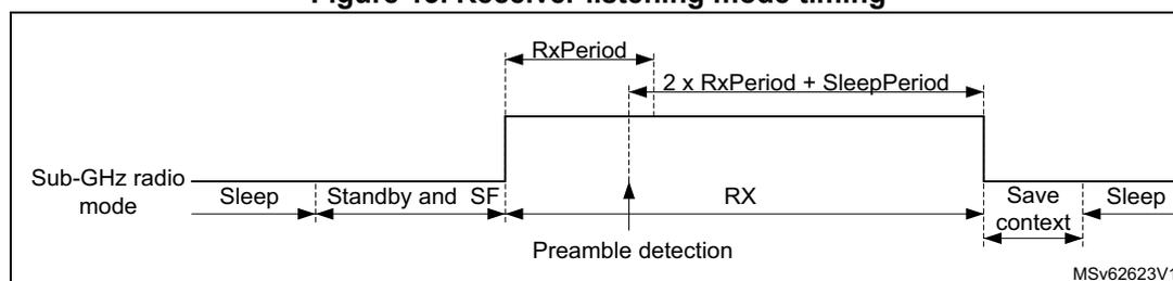
The diagram illustrates the timing sequence for the receiver listening mode. The horizontal axis represents time, and the vertical axis represents the Sub-GHz radio mode. The sequence starts with 'Sleep', followed by 'Standby and SF'. When 'RX' mode is entered, a 'Preamble detection' occurs. The 'RX' mode duration is defined by 'RxPeriod' and '2 x RxPeriod + SleepPeriod'. After the 'RX' mode, the radio enters 'Save context' and then 'Sleep' again.
Set_Cad() command
Set_Cad()
is used to detect the channel activity and can only be used with LoRa packet types. The channel activity detection (CAD) is a specific LoRa operation mode, where the sub-GHz radio searches for a LoRa radio signal. After the search is completed, the Standby mode is automatically entered, CAD is done and IRQ is generated. When a LoRa radio signal is detected, the CAD detected IRQ is also generated.
| 0 |
| Opcode |
| w |
byte 0 bits 7:0 Opcode: 0xC5
The length of the search must be configured with
Set_CadParams()
prior sending
Set_Cad()
.
Set_TxContinuousWave() command
Set_TxContinuousWave()
is a test command to generate a continuous transmit tone at the RF-PLL frequency. The sub-GHz radio remains in continuous transmit tone mode until a mode configuration command is received.
| 0 |
| Opcode |
| w |
byte 0 bits 7:0 Opcode: 0xD1
Set_TxContinuousPreamble() command
Set_TxContinuousPreamble()
is a test command to generate an infinite preamble at the RF-PLL frequency.
The preamble is an alternating 0s and 1s sequence in generic (G)FSK and (G)MSK modulations. The preamble is symbol 0 in LoRa modulation.
The sub-GHz radio remains in infinite preamble mode until a mode configuration command is received.
| 0 |
| Opcode |
| w |
byte 0 bits 7:0 Opcode: 0xD2
4.8.4 Sub-GHz radio configuration commands
Set_PacketType() command
Set_PacketType(PktType)
allows the selection of packet frame format. This command must be the first command of a sub-GHz radio configuration sequence.
Changing from one sub-GHz radio configuration to another is done using
Set_PacketType()
. The parameters from the previous sub-GHz radio configuration are lost. The switch from one configuration mode to another is only accepted in Standby mode.
| 0 | 1 |
|---|---|
| Opcode | PktType |
| w | w |
byte 0 bits 7:0 Opcode: 0x8A.
byte 1 bits 7:2 Reserved, must be kept at reset value.
bits 1:0 PktType[1:0]: Packet type definition
- 0: FSK generic packet type
- 1: LoRa packet type
- 2: BPSK packet type
- 3: MSK generic packet type
- Other: reserved
Get_PacketType() command
Get_PacketType(Status, PktType)
returns information on the selected packet frame format.
Changing from one sub-GHz radio configuration to another is done using
Set_PacketType()
. The parameters from the previous sub-GHz radio configuration are lost. The switch from one configuration mode to another is only accepted in Standby mode.
| 0 | 1 | 2 |
|---|---|---|
| Opcode | Status[7:0] | PktType |
| w | r | r |
byte 0 bits 7:0 Opcode: 0x11
byte 1 bits 7:0 Status[7:0]: see Get_Status() command
byte 2 bits 7:2 Reserved, must be kept at reset value.
bits 1:0 PktType[1:0]: Packet type definition
- 0: FSK generic packet type
- 1: LoRa packet type
- 2: BPSK packet type
- 3: MSK generic packet type
- Others: reserved
Set_RfFrequency() command
Set_RfFrequency(RfFreq) is used to lock the RF-PLL frequency to the transmit and receive frequency.
| 0 | 1 | 2 | 3 | 4 |
|---|---|---|---|---|
| Opcode | RfFreq[31:0] | |||
| w | w | w | w | w |
byte 0 bits 7:0 Opcode: 0x86
bytes 4:1 bits 31:0 RfFreq[31:0]: RF frequency
Set_TxParams() command
Set_TxParams(Power, RampTime) is used to set the transmit output power and the PA ramp-up time.
| 0 | 1 | 2 |
|---|---|---|
| Opcode | Power[7:0] | RampTime[7:0] |
| w | w | w |
byte 0 bits 7:0 Opcode: 0x8E
byte 1 bits 7:0 Power[7:0]: Output power setting
LP PA selected in Set_PaConfig()
0x0E: + 14 dB
...
0x00: 0 dB
...
0xEF: - 17 dB
Others: reserved
HP PA selected in Set_PaConfig()
0x16: + 22 dB
...
0x00: 0 dB
...
0xF7: - 9 dB
Others: reserved
byte 2 bits 7:0 RampTime[7:0] : PA ramp time for FSK, MSK and LoRa modulation
0x00: 10 µs
0x01: 20 µs
0x02: 40 µs
0x03: 80 µs
0x04: 200 µs
0x05: 800 µs
0x06: 1700 µs
0x07: 3400 µs
Others: reserved
Note: In BPSK mode, the ramping time is specific and RampTime[7:0] is not used.
Set_PaConfig() command
Set_PaConfig(PaDutyCycle, HpMax, PaSel, 0x01)
is used to customize the maximum output power and PA efficiency.
| 0 | 1 | 2 | 3 | 4 |
|---|---|---|---|---|
| Opcode | PaDutyCycle[2:0] | HpMax[2:0] | PaSel | 0x01 |
| w | w | w | w | w |
byte 0 bits 7:0 Opcode : 0x95
byte 1 bits 7:3 Reserved, must be kept at reset value.
bits 2:0 PaDutyCycle[2:0] : PA duty cycle (conduit angle) control
Duty cycle = \( 0.2 + 0.04 \times \text{PaDutyCycle}[2:0] \) (see Table 27 for settings)
Caution: The following restrictions must be observed to avoid over-stress on the PA:
- - LP PA mode with synthesis frequency >400 MHz, PaDutyCycle must be \( \leq 0x7 \) .
- - LP PA mode with synthesis frequency < 400 MHz, PaDutyCycle must be \( \leq 0x4 \) .
- - HP PA mode, PaDutyCycle must be \( \leq 0x4 \) .
byte 2 bits 2:0 HpMax[2:0] : HP PA output power (see Table 27 for settings)
bits 7:3 Reserved, must be kept at reset value.
byte 3 bits 7:1 Reserved, must be kept at reset value.
bit 0 PaSel : PA selection.
0: HP PA selected
1: LP PA selected (default)
byte 4 bits 7:0 0x01
PA optimal settings given in the table below must be used to maximize the PA efficiency for the maximum targeted output power. Matching network determination must be done using these settings (see the application note AN5457 for more details).
Table 27. PA optimal setting and operating modes
| Output power (dBm) | PA mode | Set_PaConfig() | Set_TxParams() | ||
|---|---|---|---|---|---|
| PaDutyCycle [2:0] | HpMax[2:0] | PaSel | Power | ||
| + 15 | LP | 0x7 | 0x0 | 1 | 0x0E |
| + 14 | 0x4 | 0x0 | 1 | 0x0E | |
| + 10 | 0x1 | 0x0 | 1 | 0x0D | |
| + 22 | HP | 0x4 | 0x7 | 0 | 0x16 |
| + 20 | 0x3 | 0x5 | 0 | 0x16 | |
| + 17 | 0x2 | 0x3 | 0 | 0x16 | |
| + 14 | 0x2 | 0x2 | 0 | 0x16 | |
Set_TxRxFallbackMode() command
Set_TxRxFallbackMode(FallbackMode) defines the operating mode to enter after a successful packet transmission or packet reception.
| 0 | 1 |
|---|---|
| Opcode | FallbackMode[7:0] |
| w | w |
byte 0 bits 7:0 Opcode : 0x93
byte 1 bits 7:0 FallbackMode[7:0] : Fall-back mode after successful packet transmission or packet reception
0x20: Standby mode entry (default)
0x30: Standby with HSE32 enabled mode entry
0x40: FS mode entry
Others: reserved
Set_CadParams() command
Set_CadParams(NbCadSymbol, CadDetPeak, CadDetMin, CadExitMode, Timeout) allows the CAD configuration for LoRa packet types.
| 0 | 1 | 2 | 3 | 4 | 5 | 6 | 7 |
|---|---|---|---|---|---|---|---|
| Opcode | NbCadSymbol[2:0] | CadDetPeak[7:0] | CadDetMin[7:0] | CadExitMode | Timeout[23:0] | ||
| w | w | w | w | w | w | w | w |
- byte 0 bits 7:0 Opcode: 0x88
- byte 1 bits 7:3 Reserved, must be kept at reset value.
- bits 2:0
NbCadSymbol[2:0]:
Number of symbols used for CAD scan
- 0x0: 1 symbol
- 0x1: 2 symbols
- 0x2: 4 symbols
- 0x3: 8 symbols
- 0x4: 16 symbols
- Others: reserved
- bits 2:0
NbCadSymbol[2:0]:
Number of symbols used for CAD scan
- byte 2 bits 7:0
CadDetPeak[7:0]:
Used with CadDetMin[7:0] to correlate the LoRa symbol
See Table 28 . - byte 3 bits 7:0
CadDetMin[7:0]:
Used with CadDetPeak[7:0] to correlate the LoRa symbol
see Table 28 . - byte 4 bits 7:1 Reserved, must be kept at reset value.
- Bit 0
CadExitMode:
defines the sub-GHz radio operating mode to enter after CAD scan is finished
- 0: Standby with RC 13 MHz mode entry after CAD, whatever is detected during the CAD scan
- 1: Standby with RC 13 MHz mode after CAD if no LoRa symbol is detected during the CAD scan
- if a LoRa symbol is detected, the sub-GHz radio stays in Receive mode until a packet is received or until the CAD timeout is reached.
- Bit 0
CadExitMode:
defines the sub-GHz radio operating mode to enter after CAD scan is finished
- bytes 7:5 bits 23:0
Timeout[23:0]:
CAD timeout = Timeout[23:0] x 15.625 µs
- The CAD timeout is only used when a symbol is detected and CadExitMode = 1 (stay in Receive mode after a LoRa symbol detection).
- 0x000000 - 0xFFFFFF: timeout, resolution 15.625 µs
The correct values selected in the table below must be carefully tested to ensure a good detection at sensitivity level and to limit the number of false detections.
Table 28. Recommended CAD configuration settings
| Spreading factor | cadDetMin | cadDetPeak | cadSymbolNum |
|---|---|---|---|
| SF7 | 10 | 22 | 2 symbols |
| SF8 | |||
| SF9 | 23 | 4 symbols | |
| SF10 | 24 | ||
| SF11 | 25 | ||
| SF12 | 28 |
Set_BufferBaseAddress() command
Set_BufferBaseAddress(TxBaseAddr, RxBaseAddr) sets the data buffer base address for the packet handling in TX and RX.
| 0 | 1 | 2 |
|---|---|---|
| Opcode | TxBaseAddr[7:0] | RxBaseAddr[7:0] |
| w | w | w |
byte 0 bits 7:0 Opcode: 0x8F
byte 1 bits 7:0 TxBaseAddr[7:0]: Tx base address offset relative to the sub-GHz RAM base address
byte 2 bits 7:0 RxBaseAddr[7:0]: Rx base address offset relative to the sub-GHz RAM base address
(G)FSK Set_ModulationParams() command
Set_ModulationParams(Br, PulseShape, Bw, Fdev) is used to configure the (G)FSK modulation parameters for the sub-GHz radio. Depending on the selected packet type in Set_PacketType() sent prior to this function, the parameters for generic packets are interpreted as follows:
- • Br and Fdev are used for the transmission and reception.
- • Bw is used only for reception.
- • PulseShape represents the Gaussian filter that can be used to filter the modulation stream at the transmitter.
| 0 | 1 | 2 | 3 | 4 | 5 | 6 | 7 | 8 | ||
|---|---|---|---|---|---|---|---|---|---|---|
| Opcode | Br[23:0] | PulseShape[7:0] | Bw[7:0] | Fdev[23:0] | ||||||
| w | w | w | w | w | ||||||
byte 0 bits 7:0 Opcode: 0x8B
bytes 3:1 bits 23:0 Br[23:0]: Bit rate
0x000000: reserved
0x000001 - 0xFFFFF: Br = 32 x 32 MHz / bit rate
byte 4 bits 7:0 PulseShape[7:0]: Pulse shape
0x00: no filter applied
0x08: Gaussian BT 0.3
0x09: Gaussian BT 0.5
0x0A: Gaussian BT 0.7
0x0B: Gaussian BT 1.0
Others: no filter applied
bytes 5 bit 7:0 Bw[7:0] : Bandwidth0x1F: BW4 4.8 kHz DSB
0x17: BW5 5.8 kHz DSB
0x0F: BW7 7.3 kHz DSB
0x1E: BW9 9.7 kHz DSB
0x16: BW11 11.7 kHz DSB
0x0E: BW14 14.6 kHz DSB
0x1D: BW19 19.5 kHz DSB
0x15: BW23 23.4 kHz DSB
0x0D: BW29 29.3 kHz DSB
0x1C: BW39 39.0 kHz DSB
0x14: BW46 46.9 kHz DSB
0x0C: BW58 58.6 kHz DSB
0x1B: BW78 78.2 kHz DSB
0x13: BW93 93.8 kHz DSB
0x0B: BW117 117.3 kHz DSB
0x1A: BW156 156.2 kHz DSB
0x12: BW187 187.2 kHz DSB
0x0A: BW234 234.3 kHz DSB
0x19: BW312 312.0 kHz DSB
0x11: BW373 373.6 kHz DSB
0x09: BW467 467.0 kHz DSB
Others: reserved
LoRa Set_ModulationParams() command
Set_ModulationParams(Sf, Bw, Cr, Ldro)
is used to configure the LoRa modulation parameters for the sub-GHz radio. Depending on the selected packet type in
Set_PacketType()
sent prior to this function, the parameters for LoRa are interpreted as below.
| 0 | 1 | 2 | 3 | 4 |
|---|---|---|---|---|
| Opcode | Sf[3:0] | Bw[7:0] | Cr[2:0] | Ldro |
| w | w | w | w | w |
byte 1 bits 7:4 Reserved, must be kept at reset value.
bits 3:0
Sf[3:0]
: Spreading factor
0x5: Spreading factor 5
0x6: Spreading factor 6
0x7: Spreading factor 7
0x8: Spreading factor 8
0x9: Spreading factor 9
0xA: Spreading factor 10
0xB: Spreading factor 11
0xC: Spreading factor 12
Others: reserved
- byte 2 bits 7:0 Bw[7:0] : Bandwidth
- 0x00: bandwidth 7 (7.81 kHz)
- 0x08: bandwidth 10 (10.42 kHz)
- 0x01: bandwidth 15 (15.63 kHz)
- 0x09: bandwidth 20 (20.83 kHz)
- 0x02: bandwidth 31 (31.25 kHz)
- 0x0A: bandwidth 41 (41.67 kHz)
- 0x03: bandwidth 62 (62.50 kHz)
- 0x04: bandwidth 125 (125 kHz)
- 0x05: bandwidth 250 (250 kHz)
- 0x06: bandwidth 500 (500 kHz)
- Others: reserved
- byte 3 bits 7:3 Reserved, must be kept at reset value.
- bits 2:0 Cr[2:0] : Forward error correction coding rate
- 0x0: no forward error correction coding rate 4/4
- 0x1: forward error correction coding rate 4/5
- 0x2: forward error correction coding rate 4/6
- 0x3: forward error correction coding rate 4/7
- 0x4: forward error correction coding rate 4/8
- Others: reserved
- byte 4 bits 7:1 Reserved, must be kept at reset value.
- bit 0 Ldro : low data rate optimization enable
- 0: low data rate optimization disabled
- 1: low data rate optimization enabled
BPSK Set_ModulationParams() command
Set_ModulationParams(Br, PulseShape)
is used to configure the BPSK modulation parameters for the sub-GHz radio. Depending on the selected packet type in
Set_PacketType()
sent prior to this function, the parameters for BPSK packets are interpreted as follows:
- • For BPSK packet type, the BitRate is used for the transmission.
- • PulseShape represents the Gaussian filter that can be used to filter the modulation stream at the transmitter.
| 0 | 1 | 2 | 3 | 4 |
|---|---|---|---|---|
| Opcode | Br[23:0] | PulseShape[7:0] | ||
| w | w | w | w | w |
- byte 0 bits 7:0 Opcode : 0x8B
- bytes 3:1 bits 23:0 Br[23:0] : bit rate
- 0x000000: reserved
- 0x000001 - 0xFFFFFFFF: \( Br = 32 \times 32 \text{ MHz} / \text{bit rate} \)
- 0x1A0AAA: 600 bit/s
- 0x9C4000: 100 bit/s
- byte 4 bits 7:0 PulseShape[7:0] : Pulse shape
- 0x16: Gaussian BT 0.5
- Others: reserved
Generic Set_PacketParams() command
Set_PacketParams(PbLength, PbDetLength, SynchWordLength, AddrComp, PktType, PayloadLength, CrcType, Whitening) is used to configure the packet handling for the sub-GHz radio. When the generic packet is selected with packet type in Set_PacketType() sent prior to this function, the parameters are interpreted as below.
| 0 | 1 | 2 | 3 | 4 | 5 | 6 | 7 | 8 | 9 |
|---|---|---|---|---|---|---|---|---|---|
| Opcode | PbLength[15:0] | PbDetLength[2:0] | SyncWordLength[6:0] | AddrComp[1:0] | PktType | PayloadLength[7:0] | CrcType[2:0] | Whitening | |
| w | w | w | w | w | w | w | w | w | w |
byte 0 bits 7:0 Opcode : 0x8C.
bytes 2:1 bits 15:0 PbLength[15:0] : Preamble length in number of symbols
- 0x0000: reserved
- 0x0001 - 0xFFFF: 1 to 65535 symbols
byte 3 bits 7:3 Reserved, must be kept at reset value.
bits 2:0 PbDetLength[2:0] : Preamble detection length in number of bit symbols
- 0x0: preamble detection disabled
- 0x4: 8-bit preamble detection
- 0x5: 16-bit preamble detection
- 0x6: 24-bit preamble detection
- 0x7: 32-bit preamble detection
- Others: reserved
byte 4 bit 7 Reserved, must be kept at reset value.
bits 6:0 SyncWordLength[6:0] : Synchronization word length in number of bit symbols
- 0x00 - 0x40: 0 to 64-bit synchronization word (synchronization word data defined in SUBGHZ_GSYNCR[0:7])
- Others: reserved
byte 5 bits 7:2 Reserved, must be kept at reset value.
bits 1:0 AddrComp[1:0] : Address comparison/filtering
- 0x0: address comparison/filtering disabled
- 0x1: address comparison/filtering on node address
- 0x2: address comparison/filtering on node and broadcast addresses
- Others: reserved
byte 6 bits 7:1 Reserved, must be kept at reset value.
bit 0 PktType : Packet type definition
- 0: Fixed payload length and header field not added to packet
- 1: Variable payload length and header field added to packet
byte 7 bits 7:0 PayloadLength[7:0] : Payload length in number of bytes
- 0x00- 0xFF: 0 to 255 bytes
byte 8 bits 7:3 Reserved, must be kept at reset value.
bits 2:0 CrcType[2:0] : CRC type definition
The CRC initialization value is provided in SUBGHZ_GCRCINIRL and SUBGHZ_GCRCINIRH. The polynomial is defined in SUBGHZ_GCRCPOLRL and SUBGHZ_GCRCPOLRH.
0x0: 1-byte CRC
0x1: no CRC
0x2: 2-byte CRC
0x4: 1-byte inverted CRC
0x6: 2-byte inverted CRC
Others: reserved
byte 9 bits 7:1 Reserved, must be kept at reset value.
bit 0 Whitening : Whitening enable
The whitening initial value is provided in WHITEINI[8:0].
0: Whitening disabled
1: Whitening enabled
LoRa Set_PacketParams() command
Set_PacketParams(PbLength, HeaderType, PayloadLength, CrcType, InvertIQ) is used to configure the packet handling for the sub-GHz radio. Depending on the selected packet type in Set_PacketType() sent prior to this function, the parameters are interpreted as below.
| 0 | 1 | 2 | 3 | 4 | 5 | 6 | |
|---|---|---|---|---|---|---|---|
| Opcode | PbLength[15:0] | HeaderType | PayloadLength[7:0] | CrcType | InvertIQ | ||
| w | w | w | w | w | w | ||
byte 0 bits 7:0 Opcode : 0x8C.
bytes 2:1 bits 15:0 PbLength[15:0] : Preamble length in number of symbols
0x0000: reserved
0x0001 - 0xFFFF: 1 to 65535 symbols
byte 3 bits 7:1 Reserved, must be kept at reset value.
bit 0 HeaderType : Header type definition
0: explicit header for variable length payload
1: implicit header for fixed length payload
byte 4 bits 7:0 PayloadLength[7:0] : Payload length in number of bytes
0x00- 0xFF: 0 to 255 bytes
byte 5 bits 7:1 Reserved, must be kept at reset value.
bit 0 CrcType CRC enable
0: CRC disabled
1: CRC enabled
byte 6 bits 7:1 Reserved, must be kept at reset value.
bit 0 InvertIQ : IQ setup
0: standard IQ setup
1: inverted IQ setup
BPSK Set_PacketParams() command
Set_PacketParams(PayloadLength)
is used to configure the packet handling for the sub-GHz radio. When the BPSK packet is selected with packet type in
Set_PacketType()
sent prior to this function, the parameters are interpreted as below.
| 0 | 1 |
|---|---|
| Opcode | PayloadLength[7:0] |
| w | w |
byte 0 bits 7:0 Opcode : 0x8C.
byte 1 bits 7:0 PayloadLength[7:0] : BPSK packet (payload) length, including preamble, synch word, device id and CRC, in number of bytes
0x00- 0xFF: 0 to 255 bytes
LoRa Set_LoRaSymbTimeout() command
Set_LoRaSymbTimeout(SymbNum)
is used to configure the number of LoRa symbols to be received before starting the reception of a LoRa packet.
| 0 | 1 |
|---|---|
| Opcode | SymbNum[7:0] |
| w | w |
byte 0 bits 7:0 Opcode : 0xA0.
byte 1 bits 7:0 SymbNum[7:0] : Number of LoRa symbols before timeout IRQ is generated if end of preamble has not been detected
0x0: No detection of end of preamble
Others: When setting SymbNum to a value \( \neq 0 \) , the modem counts the number of received chirp after the first LoRa chirp is detected. The modem checks that the end of preamble is detected before the SymbNum number of LoRa symbol is obtained after the first chirp is detected. If this is not the case, a timeout is generated.
Note: In LoRa packet type, when entering the Receive mode and SymbNum[7:0] = 0x0, the modem locks as soon as a single LoRa symbol is detected. This may lead to a false detection. To avoid false detections, the number of LoRa symbols to be detected can be increased.
4.8.5 Communication status information commands
Get_Status() command
Get_Status(Status) can be issued at any time.
| 0 | 1 |
|---|---|
| Opcode | Status[7:0] |
| w | r |
byte 0 bits 7:0 Opcode: 0xC0
byte 1 bit 7 Reserved, must be kept at reset value.
bits 6:4 Status_Mode[2:0] sub-GHz radio operating mode
0x2: Standby mode with RC 13 MHz
0x3: Standby mode with HSE32
0x4: FS mode
0x5: RX mode
0x6: TX mode
Others: reserved
bits 3:1 Status_CmdStatus[2:0] : Command status
0x2: data available to host (packet received successfully and data can be retrieved)
0x3: command time out (command took too long to complete triggering a sub-GHz radio watchdog timeout)
0x4: command processing error (invalid opcode or incorrect number of parameters)
0x5: command execution failure (command successfully received but cannot be executed at this time, requested operating mode cannot be entered or requested data cannot be sent)
0x6: transmit command completed (current packet transmission completed)
Others: reserved
bit 0 Reserved, must be kept at reset value.
Get_RxBufferStatus() command
Get_RxBufferStatus(Status, RxPayloadLength, RxBufferPointer) returns the sub-GHz radio status, the length of the last received packet (RxPayloadLength) and the buffer address of the first received payload byte (RxBufferPointer).
| 0 | 1 | 2 | 3 |
|---|---|---|---|
| Opcode | Status[7:0] | RxPayloadLength[7:0] | RxBufferPointer[7:0] |
| w | r | r | r |
byte 0 bits 7:0 Opcode: 0x13.
byte 1 bits 7:0 Status[7:0] : see Get_Status() command .
byte 2 bits 7:0 RxPayloadLength[7:0] : indicate the number of bytes received in the last received packet
byte 3 bits 7:0 RxBufferPointer[7:0] : indicates the offset in the RAM data buffer where the first byte of the last received packet is stored
(G)FSK Get_PacketStatus() command
Get_PacketStatus(Status, RxStatus, RssiSync, RssiAvg) returns information on the last received packet. Depending on the selected packet type in Set_PacketType() sent prior to this function, the parameters for generic packets are interpreted as below.
| 0 | 1 | 2 | 3 | 4 |
|---|---|---|---|---|
| Opcode | Status[7:0] | RxStatus[7:0] | RssiSync[7:0] | RssiAvg[7:0] |
| w | r | r | r | r |
byte 0 bits 7:0 Opcode : 0x14
byte 1 bits 7:0 Status[7:0] : see Get_Status() command
byte 2
- bit 7 RxStatus_PreambleErr : Set when a preamble error occurred
- bit 6 RxStatus_SyncErr : Set when a synchronization error occurred
- bit 5 RxStatus_AdrsErr : Set when an address error occurred
- bit 4 RxStatus_CrcErr : Set when a crc error occurred
- bit 3 RxStatus_LengthErr : Set when a length error occurred
- bit 2 RxStatus_AbortErr : Set when an abort error occurred
- bit 1 RxStatus_PktReceived : Set when a packet is received
- bit 0 RxStatus_PktSent : Set when a packet has been sent
byte 3 bits 7:0
RssiSync[7:0]
: RSSI level when the synchronization address is detected
Signal power =
\(
-RssiSync / 2
\)
(in dBm)
byte 4 bits 7:0
RssiAvg[7:0]
: Average RSSI level over the received packet
Signal power =
\(
-RssiAvg / 2
\)
(in dBm)
LoRa Get_PacketStatus() command
Get_PacketStatus(Status, RssiPkt, SnrPkt, SignalRssiPkt) returns information on the last received packet. Depending on the selected packet type in Set_PacketType() sent prior to this function, the parameters for LoRa packets are interpreted as below.
| 0 | 1 | 2 | 3 | 4 |
|---|---|---|---|---|
| Opcode | Status[7:0] | RssiPkt[7:0] | SnrPkt[7:0] | SignalRssiPkt |
| w | r | r | r | r |
byte 0 bits 7:0 Opcode : 0x14
byte 1 bits 7:0 Status[7:0] : see Get_Status() command
byte 2 bits 7:0
RssiPkt[7:0]
: Average RSSI level over the received packet
Signal power =
\(
- RssiPkt / 2
\)
(in dBm)
byte 3 bits 7:0
SnrPkt[7:0]
: Estimation of SNR over the received packet
SNR =
\(
SnrPkt / 4
\)
(in dB)
byte 4 bits 7:0
SignalRssiPkt[7:0]
: Estimation of RSSI level of the LoRa signal after despreading
Signal power =
\(
- SignalRssiPkt / 2
\)
(in dBm)
Get_RssiInst() command
Get_RssiInst(Status, RssiInst) returns the instantaneous signal strength while in RX mode.
| 0 | 1 | 2 |
|---|---|---|
| Opcode | Status[7:0] | RssiInst[7:0] |
| w | r | r |
byte 0 bits 7:0 Opcode: 0x15
byte 1 bits 7:0 Status[7:0]: see Get_Status() command
byte 2 bits 7:0 RssiInst[7:0]: instantaneous RSSI level at the reception time
Signal power = \( -\text{RssiInst} / 2 \) (in dBm)
(G)FSK Get_Stats() command
Get_Stats(Status, NbPktReceived, NbPktCrcError, NbPktLengthError) returns statistics information on the last received packet. Depending on the selected packet type in Set_PacketType() sent prior to this function, the parameters for generic packets are interpreted as below.
| 0 | 1 | 2 | 3 | 4 | 5 | 6 | 7 |
|---|---|---|---|---|---|---|---|
| Opcode | Status[7:0] | NbPktReceived[15:0] | NbPktCrcError[15:0] | NbPktLengthError[15:0] | |||
| w | r | r | r | r | r | r | r |
byte 0 bits 7:0 Opcode: 0x10
byte 1 bits 7:0 Status[7:0]: see Get_Status() command
bytes 3:2 bits 15:0 NbPktReceived[15:0]: Number of packets received
bytes 5:4 bits 15:0 NbPktCrcError[15:0]: Number of packets received with a payload CRC error
bytes 7:6 bits 15:0 NbPktLengthError[15:0]: Number of packets received with a payload length error
LoRa Get_Stats() command
Get_Stats(Status, NbPktReceived, NbPktCrcError, NbPktHeaderError) returns statistics information on the last received packet. Depending on the selected packet type in Set_PacketType() sent prior to this function, the parameters for LoRa packets are interpreted as below.
| 0 | 1 | 2 | 3 | 4 | 5 | 6 | 7 |
|---|---|---|---|---|---|---|---|
| Opcode | Status[7:0] | NbPktReceived[15:0] | NbPktCrcError[15:0] | NbPktHeaderError[15:0] | |||
| w | r | r | r | r | r | r | r |
byte 0 bits 7:0 Opcode: 0x10
byte 1 bits 7:0 Status[7:0]: see Get_Status() command
bytes 3:2 bits 15:0 NbPktReceived[15:0]: Number of packets received
bytes 5:4 bits 15:0 NbPktCrcError[15:0]: Number of packets received with a payload CRC error.
bytes 7:6 bits 15:0 NbPktHeaderError[15:0] : Number of packets received with a header CRC error
Reset_Stats() command
Reset_Stats(0x00, 0x00, 0x00, 0x00, 0x00, 0x00) resets the received packet statistics as reported in Get_Stats() (NbPktReceived, NbPktCrcError, NbPktlengthError and NbPktHeaderError).
| 0 | 1 | 2 | 3 | 4 | 5 | 6 |
|---|---|---|---|---|---|---|
| Opcode | 0x00 | 0x00 | 0x00 | 0x00 | 0x00 | 0x00 |
| w | w | w | w | w | w | w |
byte 0 bits 7:0 Opcode : 0x0
byte 1 bits 7:0 0x0
byte 2 bits 7:0 0x0
byte 3 bits 7:0 0x0
byte 4 bits 7:0 0x0
byte 5 bits 7:0 0x0
byte 6 bits 7:0 0x0
4.8.6 IRQ interrupt commands
There are three IRQ interrupts that can be mapped to several sub-GHz radio interrupt sources. The source of an interrupt is determined by reading the device status. Interrupts are cleared using Clr_IrqStatus().
There are 10 possible interrupt sources used depending on the packet type and operating mode. Each of these interrupt sources can be enabled or masked and mapped on any of the IRQ interrupts.
A set of commands is used to configure and control the IRQ sources and interrupt generation
Table 29. IRQ bit mapping and definition
| Bit | Source | Description | Packet type | Operation |
|---|---|---|---|---|
| 0 | TxDone | Packet transmission finished | LoRa and GFSK | Tx |
| 1 | RxDone | Packet reception finished | LoRa and GFSK | Rx |
| 2 | PreambleDetected | Preamble detected | LoRa and GFSK | Rx |
| 3 | SyncDetected | Synchronization word valid | GFSK | Rx |
| 4 | HeaderValid | Header valid | LoRa | Rx |
| 5 | HeaderErr | Header CRC error | LoRa | Rx |
| 6 | Err | preamble, syncword, address, CRC or length error | GFSK | Rx |
| CrcErr | CRC error | LoRa | Rx |
Table 29. IRQ bit mapping and definition (continued)
| Bit | Source | Description | Packet type | Operation |
|---|---|---|---|---|
| 7 | CadDone | Channel activity detection finished | LoRa | Cad |
| 8 | CadDetected | Channel activity detected | LoRa | Cad |
| 9 | Timeout | RX or TX timeout | LoRa and GFSK | Rx and Tx |
| 15:10 | Not applicable | Reserved | Not applicable | |
Cfg_DioIrq() command
Cfg_DioIrq(IrqMask, Irq1Mask, Irq2Mask, Irq3Mask) allows interrupts to be masked and mapped on the IRQ lines.
| 0 | 1 | 2 | 3 | 4 | 5 | 6 | 7 | 8 |
|---|---|---|---|---|---|---|---|---|
| Opcode | IrqMask[15:0] | Irq1Mask[15:0] | Irq2Mask[15:0] | Irq3Mask[15:0] | ||||
| w | w | w | w | w | w | w | w | w |
byte 0 bits 7:0 Opcode : 0x08
bytes 2:1 bits 15:0 IrqMask[15:0] : Global interrupt enable
See Table 29 for interrupt bit map definition. For each bit:
0: IRQ disabled
1: IRQ enabled
bytes 4:3 bits 15:0 Irq1Mask[15:0] : IRQ1 line Interrupt enable
0: interrupt on IRQ1 line disable
1: interrupt on IRQ1 line enabled
bytes 6:5 bits 15:0 Irq2Mask[15:0] : IRQ2 line Interrupt enable
0: interrupt on IRQ2 line disable
1: interrupt on IRQ2 line enabled
bytes 8:7 bits 15:0 Irq3Mask[15:0] : IRQ3 line Interrupt enable
0: interrupt on IRQ3 line disable
1: interrupt on IRQ3 line enabled
Get_IrqStatus() command
Get_IrqStatus(Status, IrqStatus) returns the IRQ status.
| 0 | 1 | 2 | 3 |
|---|---|---|---|
| Opcode | Status[7:0] | IrqStatus[15:0] | |
| w | r | r | r |
byte 0 bits 7:0 Opcode : 0x12
byte 1 bits 7:0 Status[7:0] : see Get_Status() command
bytes 3:2 bits 15:0 IrqStatus[15:0] : interrupt pending status information
See Table 29 for interrupt bit map definition. For each bit:
0: IRQ not pending
1: IRQ pending
Clr_IrqStatus() command
Clr_IrqStatus(ClrIrq)
clears the IRQ status flags (IrqStatus[15:0]).
| 0 | 1 | 2 | |
|---|---|---|---|
| Opcode | ClrIrq[15:0] | ||
| w | w | w | |
byte 0 bits 7:0 Opcode: 0x02
bytes 2:1 bits 15:0 ClrIrq[15:0]: Clear interrupt status
See Table 29 for interrupt bit map definition. For each bit:
0: no action
1: IRQ pending status flag cleared
4.8.7 Miscellaneous commands
Calibrate() command
Calibrate(CalibCfg)
allows one or several blocks to be calibrated at any time when in Standby mode. The blocks to calibrate are defined by CalibCfg parameter. When the calibration is ongoing, BUSY is set. A falling edge on BUSY indicates the end of all enabled calibrations.
| 0 | 1 |
|---|---|
| Opcode | CalibCfg[7:0] |
| w | w |
byte 0 bits 7:0 Opcode: 0x89
- byte 1
- bit 7 Reserved, must be kept at reset value.
- bit 6
CalibCfg_Image
: Image calibration
- 0: Image calibration disabled
- 1: Image calibration enabled
- bit 5
CalibCfg_AdcBulkP
: RF-ADC bulk P calibration
- 0: RF-ADC bulk P calibration disabled
- 1: RF-ADC bulk P calibration enabled
- bit 4
CalibCfg_AdcBulkN
: RF-ADC bulk N calibration
- 0: RF-ADC bulk N calibration disabled
- 1: RF-ADC bulk N calibration enabled
- bit 3
CalibCfg_AdcPulse
: RF-ADC pulse calibration
- 0: RF-ADC pulse calibration disabled
- 1: RF-ADC pulse calibration enabled
- bit 2
CalibCfg_Pll
: RF-PLL calibration
- 0: RF-PLL calibration disabled
- 1: RF-PLL calibration enabled
- bit 1
CalibCfg_RC13M
: Sub-GHz radio RC 13 MHz calibration
- 0: Sub-GHz radio RC 13 MHz calibration disabled
- 1: Sub-GHz radio RC 13 MHz calibration enabled
- bit 0
CalibCfg_RC64K
: Sub-GHz radio RC 64 kHz calibration
- 0: Sub-GHz radio RC 64 kHz calibration disabled
- 1: Sub-GHz radio RC 64 kHz calibration enabled
CalibrateImage() command
CalibrateImage(CalFreq1, CalFreq2) allows the image to be calibrated at given frequencies, at any time when in Standby mode. The calibration frequencies are defined by CalFreq1 and CalFreq2. When the calibration is ongoing, BUSY is set. A falling edge on BUSY indicates the end of calibration. Once performed, the calibration is valid for all frequencies between the two selected calibration frequencies. Any ISM band can be covered by selecting the applicable frequency for CalFreq1 and CalFreq2
Table 30. Image calibration for ISM bands
| ISM band [MHz] | CalIFreq1 | CalIFreq2 |
|---|---|---|
| 430 - 440 | 0x6B | 0x6F |
| 470 - 510 | 0x75 | 0x81 |
| 779 - 787 | 0xC1 | 0xC5 |
| 863 - 870 | 0xD7 | 0xDB |
| 902 - 928 | 0xE1 (default) | 0xE9 (default) |
By default, the image calibration is made in the band 902 - 928 MHz. Nevertheless it is possible to request a new calibration at other frequencies.
| 0 | 1 | 2 |
|---|---|---|
| Opcode | CalFreq1[7:0] | CalFreq2[7:0] |
| w | w | w |
byte 0 bits 7:0 Opcode: 0x98
byte 1 bits 7:0 CalFreq1[7:0]: Lower frequency of the band to calibrate (see Table 30 )
byte 2 bits 7:0 CalFreq2[7:0]: Higher frequency of the band to calibrate (see Table 30 )
The calibration frequencies are computed as follows:
Example: 0x6B = 428 MHz.
When \( \text{CalFreq1} = \text{CalFreq2} \) , the image calibration is done at a single frequency.
For frequencies between \( \text{CalFreq1} \) and \( \text{CalFreq2} \) , the calibration coefficient is linearly interpolated from the values obtained during the image calibration at \( \text{CalFreq1} \) and \( \text{CalFreq2} \) .
For frequencies \( \leq \text{CalFreq1} \) , the coefficient obtained during the image calibration at \( \text{CalFreq1} \) is used.
For frequencies \( \geq \text{CalFreq2} \) , the coefficient obtained during the image calibration at \( \text{CalFreq2} \) is used.
Set_RegulatorMode() command
Set_RegulatorMode(RegMode)
allows the sub-GHz radio supply operation mode selection, between LDO mode (default) and SMPS mode, when in Standby with HSE32 and Active modes.
| 0 | 1 |
|---|---|
| Opcode | RegMode |
| w | w |
byte 0 bits 7:0 Opcode: 0x96
byte 1 bits 7:1 Reserved, must be kept at reset value.
bit 0 RegMode: Regulator mode selection when sub-GHz radio is active
- 0: LDO mode
- 1: SMPS mode used in Standby with HSE32, FS, RX and TX modes
Note:
For the different CPU operating modes, the LDO or SMPS mode is controlled by the
SMPSEN
bit in
PWR control register 5 (PWR_CR5)
. When the sub-GHz radio or CPU selects the SMPS mode, the LDO mode selection is discarded.
Get_Error() command
Get_Error(Status, OpError)
returns the sub-GHz radio operational errors.
| 0 | 1 | 2 | 3 |
|---|---|---|---|
| Opcode | Status[7:0] | OpError[15:0] | |
| w | r | r | r |
byte 0 bits 7:0 Opcode : 0x17
byte 1 bits 7:0 Status[7:0] : see Get_Status() command
bytes 3:2 bits 15:9 Reserved, must be kept at reset value.
bit 8 OpError_PaRampError : PA ramping failed
bit 7 Reserved, must be kept at reset value.
bit 6 OpError_PllLockError : RF-PLL locking failed
bit 5 OpError_XoscStartError : HSE32 clock startup failed
bit 4 OpError_ImageCalibrationError : Image calibration failed
bit 3 OpError_AdcCalibrationError : RF-ADC calibration failed
bit 2 OpError_PllCalibrationError : RF-PLL calibration failed
bit 1 OpError_RC13MCalibrationError : Sub-GHz radio RC 13 MHz oscillator calibration failed
bit 0 OpError_RC64KCalibrationError : Sub-GHz radio RC 64 kHz oscillator calibration failed
Clr_Error() command
Clr_Error(0x00)
clears all recorded sub-GHz radio errors, as reported in
Get_Error()
(RC64KCalibrationError, RC13MCalibrationError, PllCalibrationError, AdcCalibrationError, ImageCalibrationError, XscoStartError, PllLockError and PaRampError).
| 0 | 1 |
|---|---|
| Opcode | 0x00 |
| w | w |
byte 0 bits 7:0 Opcode : 0x07
byte 1 bits 7:0 0x00
4.8.8 Set_TcxoMode command
Set_TcxoMode(RegTcxoTrim, Timeout)
is used to configure the TCXO and HSE32 ready timeout.
Table 31. Command format Set_TcxoMode()
| Byte 0 | Byte 1 | Byte 2-4 |
|---|---|---|
| Opcode = 0x97 | RegTcxoTrim[2:0] | Timeout[23:0] |
The definition of RegTcxoTrim and Timeout bytes is given in the table below.
Table 32. RegTcxoTrim and Timeout bytes definition
| Byte 1 [7:3] | Byte 1 RegTcxoTrim[2:0 (1) ] (V) | Byte 2-4 [23:0] timeout |
|---|---|---|
| Reserved | 0x0 = 1.6 | 0x000000 = timeout disabled |
| 0x1 = 1.7 | Other = timeout enabled (2) | |
| 0x2 = 1.8 | - | |
| 0x3 = 2.2 | - | |
| 0x4 = 2.4 | - | |
| 0x5 = 2.7 | - | |
| 0x6 = 3.0 | - | |
| 0x7 = 3.3 | - |
- 1. To use V DDTCXO , the V DDRF supply must be at least + 200 mV higher than the selected RegTcxoTrim voltage level.
- 2. Maximum time the system waits for the HSE32 clock to be ready, before HSEStartErr is set.
The time-out duration is computed by the following formula:
4.8.9 Sub-GHz radio commands overview
The sub-GHz radio commands are mapped as 8-bit addressable SPI commands, as described in the table below:
Table 33. Sub-GHz radio SPI commands overview
| Command | Opcode | Parameters |
|---|---|---|
| CalibratImage() | 0x98 | CalFreq1, CalFreq2 |
| Calibrate() | 0x89 | CalibCfg |
| Cfg_DioIrq() | 0x08 | IrqMask, Irq1Mask, Irq2Mask, Irq3Mask |
| Clr_Error() | 0x07 | 0x00 |
| Clr_IrqStatus() | 0x02 | ClrIrq |
| Get_Error() | 0x17 | Status, OpError |
| Get_IrqStatus() | 0x12 | Status, IrqStatus |
| Get_PacketStatus() | FSK | Status, RxStatus, RssiSync, RssiAvg |
| LoRa | Status, RssiPkt, SnrPkt, SignalRssiPkt | |
| Get_PacketType() | 0x11 | Status, PktType |
| Get_RssiInst() | 0x15 | Status, RssiInst |
| Get_RxBufferStatus() | 0x13 | Status, RxPayloadLength, RxBufferPointer |
| Get_Stats() | FSK | Status, NbPktReceived, NbPktCrcError, NbPktLengthError |
| LoRa | Status, NbPktReceived, NbPktCrcError, NbPktHeaderError |
Table 33. Sub-GHz radio SPI commands overview (continued)
| Command | Opcode | Parameters | |
|---|---|---|---|
| Get_Status() | 0xC0 | Status | |
| Read_Buffer() | 0x1E | Offset, Status, Data0, Data1, ..., Datan | |
| Read_Register() | 0x1D | Addr, Status, Data0, Data1, ..., Datan | |
| Reset_Stats() | 0x00 | 0x00, 0x00, 0x00, 0x00, 0x00, 0x00 | |
| Set_BufferBaseAddress() | 0x8F | TxBaseAddr, RxBaseAddr | |
| Set_Cad() | 0xC5 | - | |
| Set_CadParams() | 0x88 | NbCadSymbol, CadDetPeak, CadDetMin, CadExitMode, Timeout | |
| Set_Fs() | 0xC1 | - | |
| Set_LoRaSymbTimeout() | 0xA0 | SymbNum | |
| Set_ModulationParams() | FSK | 0x8B | Br, PulseShape, Bw, Fdev |
| LoRa | Sf, Bw, Cr, Ldro | ||
| BPSK | Br, PulseShape | ||
| Set_PaConfig() | 0x95 | PaDutyCycle, HpMax, HpSel, 0x01 | |
| Set_PacketParams() | Generic | 0x8C | PbLength, PdDetLength, SyncWordLength, AddrComp, PktType, PayloadLength, CrcType, Whitening |
| LoRa | PbLength, HeaderType, PayloadLength, CrcType, InvertIQ | ||
| BPSK | PayloadLength | ||
| Set_PacketType() | 0x8A | PktType | |
| Set_RegulatorMode() | 0x96 | RegMode | |
| Set_RfFrequency() | 0x86 | RfFreq | |
| Set_Rx() | 0x82 | Timeout | |
| Set_RxDutyCycle() | 0x94 | RxPeriod, SleepPeriod | |
| Set_TxRxFallbackMode() | 0x93 | FallbackMode | |
| Set_Sleep() | 0x84 | SleepCfg | |
| Set_Standby() | 0x80 | StandbyCfg | |
| Set_StopRxTimerOnPreamble() | 0x9F | RxTimeoutStop | |
| Set_TcxoMode() | 0x97 | RegTcxoTrim, Timeout | |
| Set_Tx() | 0x83 | Timeout | |
| Set_TxContinuousWave() | 0xD1 | - | |
| Set_TxContinuousPreamble() | 0xD2 | - | |
| Set_TxParams() | 0x8E | Power, RampTime | |
| Write_Buffer() | 0x0E | Offset, Data0, Data1, ..., Datan | |
| Write_Register() | 0x0D | Addr, Data0, Data1, ..., Datan |
4.9 Sub-GHz radio application configuration
The sub-GHz radio is controlled via the SPI command interface. The following sections describe the basic sequence for some sub-GHz radio operations.
After releasing the sub-GHz radio reset and waking it up with sub-GHz radio SPI NSS, the sub-GHz radio automatically performs a calibration and enters Standby mode. When the sub-GHz radio is already active, the Standby mode can be requested by
Set_Standby()
. Once BUSY goes low, the sub-GHz radio can be set in Active mode.
4.9.1 Basic sequence for LoRa, (G)MSK and (G)FSK transmit operation
The sub-GHz radio can be set in LoRa, (G)MSK or (G)FSK transmit operation mode with the following steps:
- 1. Define the location of the transmit payload data in the data buffer, with
Set_BufferBaseAddress(). - 2. Write the payload data to the transmit data buffer with
Write_Buffer(). - 3. Select the packet type (generic or LoRa) with
Set_PacketType(). - 4. Define the frame format with
Set_PacketParams(). - 5. Define synchronization word in the associated packet type SUBGHZ_xSYNCR(n) with
Write_Register(). - 6. Define the RF frequency with
Set_RfFrequency(). - 7. Define the PA configuration with
Set_PaConfig(). - 8. Define the PA output power and ramping with
Set_TxParams(). - 9. Define the modulation parameters with
Set_ModulationParams(). - 10. Enable TxDone and timeout interrupts by configuring IRQ with
Cfg_DioIrq(). - 11. Start the transmission by setting the sub-GHz radio in TX mode with
Set_Tx(). After the transmission is finished, the sub-GHz radio enters automatically the Standby mode. - 12. Wait for sub-GHz radio IRQ interrupt and read interrupt status with
Get_IrqStatus():- a) On a TxDone interrupt, the packet is successfully sent
- b) On a timeout interrupt, the transmission is timeout.
- 13. Clear interrupt with
Clr_IrqStatus(). - 14. Optionally, send a
Set_Sleep()command to force the sub-GHz radio in Sleep mode.
4.9.2 Basic sequence for LoRa and (G)FSK receive operation
The sub-GHz radio can be set in LoRa or (G)FSK receive operation mode with the following steps:
- 1. Define the location where the received payload data must be stored in the data buffer, with
Set_BufferBaseAddress(). - 2. Select the packet type (generic or LoRa) with
Set_PacketType(). - 3. Define the frame format with
Set_PacketParams(). - 4. Define synchronization word in the associated packet type SUBGHZ_xSYNCR(n) with
Write_Register(). - 5. Define the RF frequency with
Set_RfFrequency(). - 6. Define the modulation parameters with
Set_ModulationParams(). - 7. Enable RxDone and timeout interrupts by configuring IRQ with
Cfg_DioIrq(). - 8. Start the receiver by setting the sub-GHz radio in RX mode with
Set_Rx():- – When in continuous receiver mode, the sub-GHz radio remains in RX mode to look for packets until stopped with
Set_Standby(). - – In single mode (with or without timeout), when the reception is finished, the sub-GHz radio enters automatically the Standby mode.
- – In listening mode, the sub-GHz radio repeatedly switches between RX single with timeout mode and Sleep mode.
- – When in continuous receiver mode, the sub-GHz radio remains in RX mode to look for packets until stopped with
- 9. Wait for sub-GHz radio IRQ interrupt and read the interrupt status with
Get_IrqStatus():- a) On a RxDone interrupt, a packet is received:
- – Check received packet error status (header error, crc error) with
Get_IrqStatus(). - – When a valid packet is received, read the receive start buffer pointer and received payload length with
Get_RxBufferStatus(). - – Read the received payload data from the receive data buffer with
Read_Buffer().
- – Check received packet error status (header error, crc error) with
- b) On a timeout interrupt, the reception is timed out.
- a) On a RxDone interrupt, a packet is received:
- 10. Clear interrupts with
Clr_IrqStatus(). - 11. Optionally, send a
Set_Sleep()command to force the sub-GHz radio in Sleep mode.
4.9.3 Basic sequence for BPSK transmit operation
The sub-GHz radio can be set in BPSK transmit operation mode by the following steps:
- 1. Define the location of the transmit payload data in the data buffer, with
Set_BufferBaseAddress() - 2. Write the packet data (synchronization word, payload data) to the transmit data buffer with
Write_Buffer(). - 3. Select the packet type (BPSK) with
Set_PacketType(). - 4. Define the frame format with
Set_PacketParams(). - 5. Define the RF frequency with
Set_RfFrequency(). - 6. Define the PA configuration with
Set_PaConfig(). - 7. Define the PA output power and ramping with
Set_TxParams(). - 8. Define the modulation parameters with
Set_ModulationParams(). - 9. Enable TxDone and Timeout interrupts by configuring IRQ with
Cfg_DioIrq(). - 10. Start the transmission by setting the sub-GHz radio in TX mode with
Set_Tx(). After the transmission is finished, the sub-GHz radio enters automatically the Standby mode. - 11. Wait for sub-GHz radio IRQ interrupt and read interrupt status with
Get_IrqStatus():- a) On a TxDone interrupt, the packet is successfully sent.
- b) On a timeout interrupt, the transmission is timed out.
- 12. Clear interrupt with
Clr_IrqStatus(). - 13. Optionally, send a
Set_Sleep()command to force the sub-GHz radio in Sleep mode.
4.10 Sub-GHz radio registers
The sub-GHz radio peripheral registers can be accessed by sub-GHz radio command
Write_Register()
and
Read_Register()
.
4.10.1 Sub-GHz radio ramp-up MSB register (SUBGHZ_RAM_RAMPUPH)
Address offset: 0x0F0
Reset value: 0x00
| 7 | 6 | 5 | 4 | 3 | 2 | 1 | 0 |
|---|---|---|---|---|---|---|---|
| RAMPUP[15:8] | |||||||
| rw | rw | rw | rw | rw | rw | rw | rw |
Bits 7:0 RAMPUP[15:8] : Ramp-up MSB bits
4.10.2 Sub-GHz radio ramp-up LSB register (SUBGHZ_RAM_RAMPUPL)
Address offset: 0x0F1
Reset value: 0x00
| 7 | 6 | 5 | 4 | 3 | 2 | 1 | 0 |
|---|---|---|---|---|---|---|---|
| RAMPUP[7:0] | |||||||
| rw | rw | rw | rw | rw | rw | rw | rw |
Bits 7:0 RAMPUP[7:0] : Ramp-up LSB bits
4.10.3 Sub-GHz radio ramp-down MSB register (SUBGHZ_RAM_RAMPDNH)
Address offset: 0x0F2
Reset value: 0x00
| 7 | 6 | 5 | 4 | 3 | 2 | 1 | 0 |
|---|---|---|---|---|---|---|---|
| RAMPDN[15:8] | |||||||
| rw | rw | rw | rw | rw | rw | rw | rw |
Bits 7:0 RAMPDN[15:8] : Ramp-down MSB bits
4.10.4 Sub-GHz radio ramp-down LSB register (SUBGHZ_RAM_RAMPDNL)
Address offset: 0x0F3
Reset value: 0x00
| 7 | 6 | 5 | 4 | 3 | 2 | 1 | 0 |
|---|---|---|---|---|---|---|---|
| RAMPDN[7:0] | |||||||
| rw | rw | rw | rw | rw | rw | rw | rw |
Bits 7:0 RAMPDN[7:0] : Ramp-down LSB bits
4.10.5 Sub-GHz radio frame limit MSB register (SUBGHZ_RAM_FRAMELIMH)
Address offset: 0x0F4
Reset value: 0x00
| 7 | 6 | 5 | 4 | 3 | 2 | 1 | 0 |
|---|---|---|---|---|---|---|---|
| FRAMELIMH[15:8] | |||||||
| rw | rw | rw | rw | rw | rw | rw | rw |
Bits 7:0 FRAMELIMH[15:8] : frame limit MSB bits
4.10.6 Sub-GHz radio frame limit LSB register (SUBGHZ_RAM_FRAMELIML)
Address offset: 0x0F5
Reset value: 0x00
| 7 | 6 | 5 | 4 | 3 | 2 | 1 | 0 |
|---|---|---|---|---|---|---|---|
| FRAMELIML[7:0] | |||||||
| rw | rw | rw | rw | rw | rw | rw | rw |
Bits 7:0 FRAMELIML[7:0] : frame limit LSB bits
4.10.7 Sub-GHz radio generic bit synchronization register (SUBGHZ_GBSYNCR)
Address offset: 0x6AC
Reset value: 0x00
This register must be cleared to 0x00 when using packet types other than LoRa.
| 7 | 6 | 5 | 4 | 3 | 2 | 1 | 0 |
|---|---|---|---|---|---|---|---|
| Res. | SBITSYNCEN | RXDINV | BITSYNCDIS | Res. | Res. | Res. | Res. |
| rw | rw | rw |
Bit 7 Reserved, must be kept at reset value.
Bit 6 SBITSYNCEN : LoRa simple bit synchronization enable
- This bit must be cleared to 0 when using generic packet and BPSK type.
- 0: simple bit synchronization disabled
- 1: simple bit synchronization enabled
Bit 5 RXDINV : LoRa receive data inversion
- This bit must be cleared to 0 when using generic packet and BPSK type.
- 0: receive data not inverted
- 1: receive data inverted
Bit 4 BITSYNCDIS : LoRa normal bit synchronization enable
- This bit must be cleared to 0 when using generic packet and BPSK type.
- 0: normal bit synchronization enabled
- 1: normal bit synchronization disabled
Bits 3:0 Reserved, must be kept at reset value.
4.10.8 Sub-GHz radio generic CFO MSB register (SUBGHZ_GCFORH)
Address offset: 0x6B0
Reset value: 0x00
| 7 | 6 | 5 | 4 | 3 | 2 | 1 | 0 |
|---|---|---|---|---|---|---|---|
| Res. | Res. | Res. | Res. | DEMOD_CFO[3:0] | |||
| r | r | r | r | ||||
Bits 7:4 Reserved, must be kept at reset value.
Bits 3:0 DEMOD_CFO[3:0] : actual frequency error from normalized value (MSB bits)
4.10.9 Sub-GHz radio generic CFO LSB register (SUBGHZ_GCFORL)
Address offset: 0x6B1
Reset value: 0x00
| 7 | 6 | 5 | 4 | 3 | 2 | 1 | 0 |
|---|---|---|---|---|---|---|---|
| DEMOD_CFO[7:0] | |||||||
| r | r | r | r | r | r | r | r |
Bits 7:0 DEMOD_CFO[7:0] : actual frequency error from normalized value (LSB bits)
4.10.10 Sub-GHz radio generic packet control 1 register (SUBGHZ_GPKTCTL1R)
Address offset: 0x06B4
Reset value: 0x04
This register must be cleared to 0x00 when using packet types other than LoRa.
| 7 | 6 | 5 | 4 | 3 | 2 | 1 | 0 |
|---|---|---|---|---|---|---|---|
| Res | Res | Res | Res | Res | PBDETON | PBDETLEN[1:0] | |
| rw | rw | rw | |||||
Bits 7:3 Reserved, must be kept at reset value.
Bit 2 PBDETON : Preamble detection enable
Bits 1:0 PBDETLEN : Receiver preamble detection length
0b00: 8-bit preamble detection
0b01: 16-bit preamble detection
0b10: 24-bit preamble detection
0b11: 32-bit preamble detection
4.10.11 Sub-GHz radio generic packet control 1A register (SUBGHZ_GPKTCTL1AR)
Address offset: 0x6B8
Reset value: 0x21
| 7 | 6 | 5 | 4 | 3 | 2 | 1 | 0 |
|---|---|---|---|---|---|---|---|
| Res. | Res. | SYNCDETEN | CONTTX | INFSEQSEL[1:0] | INFSQEQEN | WHITEINI[8] | |
| rw | rw | rw | rw | rw | rw | ||
Bits 7:6 Reserved, must be kept at reset value.
Bit 5 SYNCDETEN : Generic packet synchronization word detection enable
Bit 4 CONTTX : Generic packet continuous transmit enable
Bits 3:2 INFSEQSEL[1:0] : Generic packet infinite sequence selection
- 00: preamble 0x5555
- 01: all zero 0x0000
- 10: all one 0xFFFF
- 11: PRBS9
Bit 1 INFSQEQEN : Generic packet infinite sequence enable
Bit 0 WHITEINI[8] : Generic packet whitening initial value MSB bit [8]
4.10.12 Sub-GHz radio generic whitening LSB register (SUBGHZ_GWHITEINIRL)
Address offset: 0x6B9
Reset value: 0x00
| 7 | 6 | 5 | 4 | 3 | 2 | 1 | 0 |
|---|---|---|---|---|---|---|---|
| WHITEINI[7:0] | |||||||
| rw | rw | rw | rw | rw | rw | rw | rw |
Bits 7:0 WHITEINI[7:0] : Generic packet whitening initial value LSB bits [7:0]
4.10.13 Sub-GHz radio generic payload length register (SUBGHZ_GRTXPLDLEN)
Address offset: 0x6BB
Reset value: 0x0F
| 7 | 6 | 5 | 4 | 3 | 2 | 1 | 0 |
|---|---|---|---|---|---|---|---|
| RTXPLDLEN[7:0] | |||||||
| rw | rw | rw | rw | rw | rw | rw | rw |
Bits 7:0 RTXPLDLEN[7:0] : Payload length FIFO match value in Rx and Tx
4.10.14 Sub-GHz radio generic CRC initial MSB register (SUBGHZ_GCRCINIRH)
Address offset: 0x6BC
Reset value: 0x1D
| 7 | 6 | 5 | 4 | 3 | 2 | 1 | 0 |
|---|---|---|---|---|---|---|---|
| CRCINI[15:8] | |||||||
| rw | rw | rw | rw | rw | rw | rw | rw |
Bits 7:0 CRCINI[15:8] : Generic packet CRC initial polynomial MSB bits [15:8]
These bits are used for CRC initialization.
4.10.15 Sub-GHz radio generic CRC initial LSB register (SUBGHZ_GCRCINIRL)
Address offset: 0x6BD
Reset value: 0x0F
| 7 | 6 | 5 | 4 | 3 | 2 | 1 | 0 |
|---|---|---|---|---|---|---|---|
| CRCINI[7:0] | |||||||
| rw | rw | rw | rw | rw | rw | rw | rw |
Bits 7:0
CRCINI[7:0]
: Generic packet CRC initial polynomial LSB bits [7:0]
These bits are used for CRC initialization.
4.10.16 Sub-GHz radio generic CRC polynomial MSB register (SUBGHZ_GCRCPOLRH)
Address offset: 0x6BE
Reset value: 0x10
| 7 | 6 | 5 | 4 | 3 | 2 | 1 | 0 |
|---|---|---|---|---|---|---|---|
| CRCPOL[15:8] | |||||||
| rw | rw | rw | rw | rw | rw | rw | rw |
Bits 7:0
CRCPOL[15:8]
: Generic packet CRC polynomial MSB bits [15:8]
These bits are used for CRC initialization.
4.10.17 Sub-GHz radio generic CRC polynomial LSB register (SUBGHZ_GCRCPOLRL)
Address offset: 0x6BF
Reset value: 0x21
| 7 | 6 | 5 | 4 | 3 | 2 | 1 | 0 |
|---|---|---|---|---|---|---|---|
| CRCPOLI[7:0] | |||||||
| rw | rw | rw | rw | rw | rw | rw | rw |
Bits 7:0
CRCPOLI[7:0]
: Generic packet CRC initial polynomial LSB bits [7:0]
These bits are used for CRC initialization.
4.10.18 Sub-GHz radio generic synchronization word control register 0 (SUBGHZ_GSYNCR0)
Address offset: 0x6C0
Reset value: 0x97
| 7 | 6 | 5 | 4 | 3 | 2 | 1 | 0 |
|---|---|---|---|---|---|---|---|
| SYNCWORD[63:56] | |||||||
| rw | rw | rw | rw | rw | rw | rw | rw |
Bits 7:0 SYNCWORD[63:56] : Eight byte of generic packet synchronization word
4.10.19 Sub-GHz radio generic synchronization word control register 1 (SUBGHZ_GSYNCR1)
Address offset: 0x6C1
Reset value: 0x23
| 7 | 6 | 5 | 4 | 3 | 2 | 1 | 0 |
|---|---|---|---|---|---|---|---|
| SYNCWORD[55:48] | |||||||
| rw | rw | rw | rw | rw | rw | rw | rw |
Bits 7:0 SYNCWORD[55:48] : Seventh byte of generic packet synchronization word
4.10.20 Sub-GHz radio generic synchronization word control register 2 (SUBGHZ_GSYNCR2)
Address offset: 0x6C2
Reset value: 0x52
| 7 | 6 | 5 | 4 | 3 | 2 | 1 | 0 |
|---|---|---|---|---|---|---|---|
| SYNCWORD[47:40] | |||||||
| rw | rw | rw | rw | rw | rw | rw | rw |
Bits 7:0 SYNCWORD[47:40] : Sixth byte of generic packet synchronization word
4.10.21 Sub-GHz radio generic synchronization word control register 3 (SUBGHZ_GSYNCR3)
Address offset: 0x6C3
Reset value: 0x25
| 7 | 6 | 5 | 4 | 3 | 2 | 1 | 0 |
|---|---|---|---|---|---|---|---|
| SYNCWORD[39:32] | |||||||
| rw | rw | rw | rw | rw | rw | rw | rw |
Bits 7:0 SYNCWORD[39:32] : Fifth byte of generic packet synchronization word
4.10.22 Sub-GHz radio generic synchronization word control register 4 (SUBGHZ_GSYNCR4)
Address offset: 0x6C4
Reset value: 0x56
| 7 | 6 | 5 | 4 | 3 | 2 | 1 | 0 |
|---|---|---|---|---|---|---|---|
| SYNCWORD[31:24] | |||||||
| rw | rw | rw | rw | rw | rw | rw | rw |
Bits 7:0 SYNCWORD[31:24] : Fourth byte of generic packet synchronization word
4.10.23 Sub-GHz radio generic synchronization word control register 5 (SUBGHZ_GSYNCR5)
Address offset: 0x6C5
Reset value: 0x53
| 7 | 6 | 5 | 4 | 3 | 2 | 1 | 0 |
|---|---|---|---|---|---|---|---|
| SYNCWORD[23:16] | |||||||
| rw | rw | rw | rw | rw | rw | rw | rw |
Bits 7:0 SYNCWORD[23:16] : Third byte of generic packet synchronization word
4.10.24 Sub-GHz radio generic synchronization word control register 6 (SUBGHZ_GSYNCR6)
Address offset: 0x6C6
Reset value: 0x65
| 7 | 6 | 5 | 4 | 3 | 2 | 1 | 0 |
|---|---|---|---|---|---|---|---|
| SYNCWORD[15:8] | |||||||
| rw | rw | rw | rw | rw | rw | rw | rw |
Bits 7:0 SYNCWORD[15:8] : Second byte of generic packet synchronization word
4.10.25 Sub-GHz radio generic synchronization word control register 7 (SUBGHZ_GSYNCR7)
Address offset: 0x6C7
Reset value: 0x64
| 7 | 6 | 5 | 4 | 3 | 2 | 1 | 0 |
|---|---|---|---|---|---|---|---|
| SYNCWORD[7:0] | |||||||
| rw | rw | rw | rw | rw | rw | rw | rw |
Bits 7:0 SYNCWORD[7:0] : First byte of generic packet synchronization word
4.10.26 Sub-GHz radio generic node address register (SUBGHZ_GNODEADR)
Address offset: 0x6CD
Reset value: 0x00
| 7 | 6 | 5 | 4 | 3 | 2 | 1 | 0 |
|---|---|---|---|---|---|---|---|
| NODEADD[7:0] | |||||||
| rw | rw | rw | rw | rw | rw | rw | rw |
Bits 7:0 NODEADD[7:0] : Node address used in FSK mode register
4.10.27 Sub-GHz radio generic broadcast address register (SUBGHZ_GBCASTADDR)
Address offset: 0x6CE
Reset value: 0x00
| 7 | 6 | 5 | 4 | 3 | 2 | 1 | 0 |
|---|---|---|---|---|---|---|---|
| BCASTADD[7:0] | |||||||
| rw | rw | rw | rw | rw | rw | rw | rw |
Bits 7:0 BCASTADD[7:0] : Broadcast address used in FSK mode register
4.10.28 Sub-GHz radio generic AFC register (SUBGHZ_GAFCR)
Address offset: 0x6D1
Reset value: 0x18
| 7 | 6 | 5 | 4 | 3 | 2 | 1 | 0 |
|---|---|---|---|---|---|---|---|
| AFC[7:0] | |||||||
| rw | rw | rw | rw | rw | rw | rw | rw |
Bits 7:0 AFC[7:0] : Automatic frequency control register
4.10.29 Sub-GHz radio LoRa payload length register (SUBGHZ_LPLDLENR)
Address offset: 0x702
Reset value: 0x00
| 7 | 6 | 5 | 4 | 3 | 2 | 1 | 0 |
|---|---|---|---|---|---|---|---|
| PLDLEN[7:0] | |||||||
| rw | rw | rw | rw | rw | rw | rw | rw |
Bits 7:0 PLDLEN[7:0] : Payload length in number of bytes, in case of LoRa fixed header
4.10.30 Sub-GHz radio synchro timeout register (SUBGHZ_LSYNCTIMEOUTR)
Address offset: 0x706
Reset value: 0x00
| 7 | 6 | 5 | 4 | 3 | 2 | 1 | 0 |
|---|---|---|---|---|---|---|---|
| SYNCTIMEOUT[7:0] | |||||||
| r | r | r | r | r | r | r | r |
Bits 7:0 SYNCTIMEOUT[7:0] : TimeoutValue = synchtimeout[7:3]*2^(2*synchtimeout[2:0]+1)
If a detection has not occurred by TimeoutValue, it goes back to Standby mode, or restart synch in continuous receive mode
Bits 7:3 synchtimeout(7:3) mantissa part
Bits 2:0 synchtimeout(2:0) exponent part
4.10.31 Sub-GHz radio LoRa IQ polarity MSB register (SUBGHZ_LIQPOLR)
Address offset: 0x735
Reset value: 0x00
| 7 | 6 | 5 | 4 | 3 | 2 | 1 | 0 |
|---|---|---|---|---|---|---|---|
| Res | Res | Res | Res | Res | Res | Res | Res |
Bits 7:0 Reserved, must be kept at reset value.
4.10.32 Sub-GHz radio LoRa IQ polarity LSB register (SUBGHZ_LIQPOLR)
Address offset: 0x736
Reset value: 0x00
| 7 | 6 | 5 | 4 | 3 | 2 | 1 | 0 |
|---|---|---|---|---|---|---|---|
| Res | Res | Res | Res | Res | Res | Res | Res |
Bits 7:0 Reserved, must be kept at reset value.
4.10.33 Sub-GHz radio LoRa synchronization word MSB register (SUBGHZ_LSYNCRH)
Address offset: 0x740
Reset value: 0x14
| 7 | 6 | 5 | 4 | 3 | 2 | 1 | 0 |
|---|---|---|---|---|---|---|---|
| SYNCWORD[15:8] | |||||||
| rw | rw | rw | rw | rw | rw | rw | rw |
Bits 7:0
SYNCWORD[15:8]
: LoRa synchronization word MSB bits [15:8]
0x14: LoRa private network
0x34: LoRa public network
Others: reserved
4.10.34 Sub-GHz radio LoRa synchronization word LSB register (SUBGHZ_LSYNCRL)
Address offset: 0x741
Reset value: 0x24
| 7 | 6 | 5 | 4 | 3 | 2 | 1 | 0 |
|---|---|---|---|---|---|---|---|
| SYNCWORD[7:0] | |||||||
| rw | rw | rw | rw | rw | rw | rw | rw |
Bits 7:0
SYNCWORD[7:0]
: LoRa synchronization word LSB bits [7:0]
0x24: LoRa private network
0x44: LoRa public network
Others: reserved
4.10.35 Sub-GHz radio Tx address pointer register (SUBGHZ_TXADPTR)
Address offset: 0x0802
Reset value: 0x00
| 7 | 6 | 5 | 4 | 3 | 2 | 1 | 0 |
|---|---|---|---|---|---|---|---|
| PTR[7:0] | |||||||
| rw | rw | rw | rw | rw | rw | rw | rw |
Bits 7:0 PTR[7:0] : TX buffer address pointer
4.10.36 Sub-GHz radio Rx address pointer register (SUBGHZ_RXADPTR)
Address offset: 0x0803
Reset value: 0x00
| 7 | 6 | 5 | 4 | 3 | 2 | 1 | 0 |
|---|---|---|---|---|---|---|---|
| PTR[7:0] | |||||||
| rw | rw | rw | rw | rw | rw | rw | rw |
Bits 7:0 PTR[7:0] : RX buffer address pointer
4.10.37 Sub-GHz radio bandwidth select register (SUBGHZ_BWSELR)
Address offset: 0x807
Reset value: 0x00
| 7 | 6 | 5 | 4 | 3 | 2 | 1 | 0 |
|---|---|---|---|---|---|---|---|
| Res | Res | Res | CHBWMANT[1:0] | CHBWEXPO[2:0] | |||
| r | r | r | r | r | |||
Bits 7:5 Reserved, must be kept at reset value.
Bits 4:3 CHBWMANT[1:0] : Channel bandwidth mantissa
Bits 2:0 CHBWEXPO[2:0] : Channel bandwidth exponent
4.10.38 Sub-GHz radio random number register 3 (SUBGHZ_RNGR3)
Address offset: 0x819
Reset value: 0x00
| 7 | 6 | 5 | 4 | 3 | 2 | 1 | 0 |
|---|---|---|---|---|---|---|---|
| RNDATA[31:24] | |||||||
| r | r | r | r | r | r | r | r |
Bits 7:0 RNDATA[31:24] : Random number data bits [31:24]
4.10.39 Sub-GHz radio random number register 2 (SUBGHZ_RNGR2)
Address offset: 0x81A
Reset value: 0x00
| 7 | 6 | 5 | 4 | 3 | 2 | 1 | 0 |
|---|---|---|---|---|---|---|---|
| RNDATA[23:16] | |||||||
| r | r | r | r | r | r | r | r |
Bits 7:0 RNDATA[23:16] : Random number data bits [23:16]
4.10.40 Sub-GHz radio random number register 1 (SUBGHZ_RNGR1)
Address offset: 0x81B
Reset value: 0x00
| 7 | 6 | 5 | 4 | 3 | 2 | 1 | 0 |
|---|---|---|---|---|---|---|---|
| RNDATA[15:8] | |||||||
| r | r | r | r | r | r | r | r |
Bits 7:0 RNDATA[15:8] : Random number data bits [15:8]
4.10.41 Sub-GHz radio random number register 0 (SUBGHZ_RNGR0)Address offset: 0x81C
Reset value: 0x00
| 7 | 6 | 5 | 4 | 3 | 2 | 1 | 0 |
|---|---|---|---|---|---|---|---|
| RNDATA[7:0] | |||||||
| r | r | r | r | r | r | r | r |
Address offset: 0x889
Reset value: 0x00
| 7 | 6 | 5 | 4 | 3 | 2 | 1 | 0 |
|---|---|---|---|---|---|---|---|
| SD[7:0] | |||||||
| rw | rw | rw | rw | rw | rw | rw | rw |
Address offset: 0x89B
Reset value: 0x00
| 7 | 6 | 5 | 4 | 3 | 2 | 1 | 0 |
|---|---|---|---|---|---|---|---|
| CALDATA[7:0] | |||||||
| rw | rw | rw | rw | rw | rw | rw | rw |
Address offset: 0x8AC
Reset value: 0x94
| 7 | 6 | 5 | 4 | 3 | 2 | 1 | 0 |
|---|---|---|---|---|---|---|---|
| SENSI_ADJUST[5:0] | PMODE[1:0] | ||||||
| rw | rw | rw | rw | rw | rw | rw | rw |
Bits 7:2
SENSI_ADJUST[5:0]
: Sensitivity Floor of AGC
This bitfield must be kept at 0x25.
Bits 1:0
PMODE[1:0]
: Receiver power mode selection between normal mode and power saving mode
00: power saving mode (reduced sensitivity)
01: boost mode level1 active (improves sensitivity at detriment of power consumption)
10: boost mode level2 active (improves a set further sensitivity at detriment of power consumption)
Others: boost mode (best receiver sensitivity)
4.10.45 Sub-GHz radio AGC reset configuration register (SUBGHZ_AGCFORSTCFGR)
Address offset: 0x8B8
Reset value: 0x14
| 7 | 6 | 5 | 4 | 3 | 2 | 1 | 0 |
|---|---|---|---|---|---|---|---|
| EN[7:0] | |||||||
| rw | rw | rw | rw | rw | rw | rw | rw |
Bits 7:0 EN[7:0] : Enable the reset generation for frequency-offset estimation
4.10.46 Sub-GHz radio AGC reset power threshold register (SUBGHZ_AGCFORSTPOWTHR)
Address offset: 0x8B9
Reset value: 0x0A
| 7 | 6 | 5 | 4 | 3 | 2 | 1 | 0 |
|---|---|---|---|---|---|---|---|
| PWRTHR[7:0] | |||||||
| rw | rw | rw | rw | rw | rw | rw | rw |
Bits 7:0 PWRTHR[7:0] : Power threshold reset for frequency-offset estimation
4.10.47 Sub-GHz radio Tx clamp register (SUBGHZ_TXCLAMPR)
Address offset: 0x8D8
Reset value: 0x00
| 7 | 6 | 5 | 4 | 3 | 2 | 1 | 0 |
|---|---|---|---|---|---|---|---|
| Res | Res | Res | Res | Res | Res | Res | Res |
Bits 7:0 Reserved, must be kept at reset value.
4.10.48 Sub-GHz radio disable LNA register (REG_ANA_LNA)Address offset: 0x8E2
Reset value: 0x00
| 7 | 6 | 5 | 4 | 3 | 2 | 1 | 0 |
|---|---|---|---|---|---|---|---|
| Res | Res | Res | Res | Res | Res | Res | Res |
Bits 7:0 Reserved, must be kept at reset value.
4.10.49 Sub-GHz radio disable mixer register (REG_ANA_MIXER)Address offset: 0x8E5
Reset value: 0x00
| 7 | 6 | 5 | 4 | 3 | 2 | 1 | 0 |
|---|---|---|---|---|---|---|---|
| Res | Res | Res | Res | Res | Res | Res | Res |
Bits 7:0 Reserved, must be kept at reset value.
4.10.50 Sub-GHz radio PA over current protection register (SUBGHZ_PAOCPR)Address offset: 0x8E7
Reset value: 0x18
| 7 | 6 | 5 | 4 | 3 | 2 | 1 | 0 |
|---|---|---|---|---|---|---|---|
| Res | Res | OCP[5:0] | |||||
| rW | rW | rW | rW | rW | rW | ||
Bits 7:6 Reserved, must be kept at reset value.
Bits 5:0 OCP[5:0] : Power amplifier over current protection level0x18: maximum 60 mA current for LP PA mode
0x38: maximum 140mA current for HP PA mode.
Others: reserved
4.10.51 Sub-GHz radio RTC control register (SUBGHZ_RTCCTLR)Address offset: 0x902
Reset value: 0x00
| 7 | 6 | 5 | 4 | 3 | 2 | 1 | 0 |
|---|---|---|---|---|---|---|---|
| Res | Res | Res | Res | Res | Res | Res | RTCEN |
| rW |
Bits 7:1 Reserved, must be kept at reset value.
Bit 0 RTCEN : Writing 1 restarts the radio RTC.
4.10.52 Sub-GHz radio RTC period MSB register (SUBGHZ_RTCPRDR2)
Address offset: 0x906
Reset value: 0x00
| 7 | 6 | 5 | 4 | 3 | 2 | 1 | 0 |
|---|---|---|---|---|---|---|---|
| RTCPRD[31:16] | |||||||
| rw | rw | rw | rw | rw | rw | rw | rw |
Bits 7:0 RTCPRD[31:16] : Updates radio RTC period (MSB)
4.10.53 Sub-GHz radio RTC period mid-byte register (SUBGHZ_RTCPRDR1)
Address offset: 0x907
Reset value: 0x00
| 7 | 6 | 5 | 4 | 3 | 2 | 1 | 0 |
|---|---|---|---|---|---|---|---|
| RTCPRD[15:8] | |||||||
| rw | rw | rw | rw | rw | rw | rw | rw |
Bits 7:0 RTCPRD[15:8] : Updates radio RTC period (mid-byte)
4.10.54 Sub-GHz radio RTC period LSB register (SUBGHZ_RTCPRDR0)
Address offset: 0x908
Reset value: 0x00
| 7 | 6 | 5 | 4 | 3 | 2 | 1 | 0 |
|---|---|---|---|---|---|---|---|
| RTCPRD[7:0] | |||||||
| rw | rw | rw | rw | rw | rw | rw | rw |
Bits 7:0 RTCPRD[7:0] : Updates radio RTC period (LSB)
4.10.55 Sub-GHz radio HSE32 OSC_IN capacitor trim register (SUBGHZ_HSEINTRIMR)
Address offset: 0x911
Reset value: 0x12
This register is retained in Sleep mode, but lost in Deep-Sleep mode.
| 7 | 6 | 5 | 4 | 3 | 2 | 1 | 0 |
|---|---|---|---|---|---|---|---|
| Res. | Res. | TRIM[5:0] | |||||
| rw | rw | rw | rw | rw | rw | ||
Bits 7:6 Reserved, must be kept at reset value.
Bits 5:0 TRIM[5:0] : HSE32 XTAL mode OSC_IN load capacitor trimming
Load capacitor trimming step size ~0.47 pF.
0x00: minimum value ~11.3 pF
...
0x12 value ~20.3 pF (default)
...
0x2F: maximum capacitor value ~33.4 pF
Others: reserved
4.10.56 Sub-GHz radio HSE32 OSC_OUT capacitor trim register (SUBGHZ_HSEOUTTRIMR)
Address offset: 0x912
Reset value: 0x12
This register is retained in Sleep mode, but lost in Deep-Sleep mode.
| 7 | 6 | 5 | 4 | 3 | 2 | 1 | 0 |
|---|---|---|---|---|---|---|---|
| Res. | Res. | TRIM[5:0] | |||||
| rw | rw | rw | rw | rw | rw | ||
Bits 7:6 Reserved, must be kept at reset value.
Bits 5:0 TRIM[5:0] : HSE32 XTAL mode OSC_OUT load capacitor trimming
Load capacitor trimming step size ~0.47 pF.
0x00: minimum value ~11.3 pF
...
0x12 value ~20.3 pF (default)
...
0x2F: maximum capacitor value ~33.4 pF
Others: reserved
4.10.57 Sub-GHz radio SMPS control 0 register (SUBGHZ_SMPSC0R)
Address offset: 0x916
Reset value: 0x00
| 7 | 6 | 5 | 4 | 3 | 2 | 1 | 0 |
|---|---|---|---|---|---|---|---|
| Res. | CLKDE | Res. | Res. | Res. | Res. | Res. | Res. |
| rw |
Bit 7 Reserved, must be kept at reset value.
Bit 6 CLKDE : SMPS clock detection enable
SMPS clock detection must be enabled before enabling the SMPS, if the application uses an external HSE clock source (not coming from XO or TCXO but from another device).
0: SMPS clock detection disabled
1: SMPS clock detection enabled
Bits 5:0 Reserved, must be kept at reset value.
4.10.58 Sub-GHz radio power control register (SUBGHZ_PCR)
Address offset: 0x91A
Reset value: 0x50
This register is retained in Sleep mode but lost in Deep-Sleep mode.
| 7 | 6 | 5 | 4 | 3 | 2 | 1 | 0 |
|---|---|---|---|---|---|---|---|
| Res. | CLE | CLV[1:0] | Res. | Res. | Res. | Res. | |
| rw | rw | rw | |||||
Bit 7 Reserved, must be kept at reset value.
Bit 6 CLE : Power-supply current limiter enable
0: power-supply current limiter disabled (unlimited current)
1: power-supply current limiter enabled (current limited according to CLV[1:0])
Bits 5:4 CLV[1:0] : Power-supply current limiter value
When the power-supply current limiter is enabled by CLEN, these bits define the maximum current limiting level.
0x0: power-supply current limiting level 25 mA
0x1: power-supply current limiting level 50 mA (default)
0x2: power-supply current limiting level 100 mA
0x3: power-supply current limiting level 200 mA
Bits 3:0 Reserved, must be kept at reset value.
4.10.59 Sub-GHz radio regulator drive control register (SUBGHZ_REGDRVCR)
Address offset: 0x91F
Reset value: 0x08
This register is retained in Sleep mode but lost in Deep-Sleep mode.
| 7 | 6 | 5 | 4 | 3 | 2 | 1 | 0 |
|---|---|---|---|---|---|---|---|
| Res | Res | Res | Res | TRIM[2:0] | EN | ||
| rw | rw | rw | rw | ||||
Bits 7:4 Reserved, must be kept at reset value.
Bits 3:1 TRIM[2:0] : Regulator drive trimming
000: 1.22
001: 1.24
010: 1.26
011: 1.28
100: 1.30(default)
101: 1.32
110: 1.34
Bit 0 EN : Regulator drive enable
4.10.60 Sub-GHz radio SMPS control 2 register (SUBGHZ_SMPSC2R)
Address offset: 0x923
Reset value: 0x06
This register is retained in Sleep mode but lost in Deep-Sleep mode.
| 7 | 6 | 5 | 4 | 3 | 2 | 1 | 0 |
|---|---|---|---|---|---|---|---|
| Res | Res | Res | Res | Res | DRV[1:0] | Res | |
| rw | rw | ||||||
Bits 7:3 Reserved, must be kept at reset value.
Bits 2:1 DRV[1:0] : SMPS maximum drive capability.
0x0: 20 mA
0x1: 40 mA
0x2: 60 mA
0x3: 100 mA (default)
Bit 0 Reserved, must be kept at reset value.
4.10.61 Sub-GHz radio register map
Table 34. SUBGHZ register map and reset values
| Offset | Register name | 7 | 6 | 5 | 4 | 3 | 2 | 1 | 0 |
|---|---|---|---|---|---|---|---|---|---|
| 0x6AC | SUBGHZ_GBSYNCR | Res. | SBITSYNCEN | RXDINV | BITSYNCDIS | Res. | Res. | Res. | Res. |
| Reset value | 0 | 0 | 0 | ||||||
| 0x6AC- 0x6B4 | Reserved | Reserved | |||||||
| 0x6B8 | SUBGHZ_GPKTCTL1AR | Res. | Res. | SYNCDENEN | CONTX | INFSQEQSEL[1:0] | INFSSQEQEN | WHITEINI[8] | |
| Reset value | 1 | 0 | 0 | 0 | 0 | 1 | |||
| 0x6B9 | SUBGHZ_GWHITEINRL | WHITEINI[7:0] | |||||||
| Reset value | 0 | 0 | 0 | 0 | 0 | 0 | 0 | 0 | |
| 0x6BC | SUBGHZ_GCRCINIRH | CRCINI[15:8] | |||||||
| Reset value | 0 | 0 | 0 | 1 | 1 | 1 | 0 | 1 | |
| 0x6BD | SUBGHZ_GCRCINIRL | CRCINI[7:0] | |||||||
| Reset value | 0 | 0 | 0 | 0 | 1 | 1 | 1 | 1 | |
| 0x6BE | SUBGHZ_GCRCPOLRH | CRCPOL[15:8] | |||||||
| Reset value | 0 | 0 | 0 | 1 | 0 | 0 | 0 | 0 | |
| 0x6BF | SUBGHZ_GCRCPOLRL | CRCPOL[7:0] | |||||||
| Reset value | 0 | 0 | 1 | 0 | 0 | 0 | 0 | 1 | |
| 0x6C0 | SUBGHZ_GSYNCR0 | SYNCWORD[63:56] | |||||||
| Reset value | 1 | 0 | 0 | 1 | 0 | 1 | 1 | 1 | |
| 0x6C1 | SUBGHZ_GSYNCR1 | SYNCWORD[55:48] | |||||||
| Reset value | 0 | 0 | 1 | 0 | 0 | 0 | 1 | 1 | |
| 0x6C2 | SUBGHZ_GSYNCR2 | SYNCWORD[47:40] | |||||||
| Reset value | 0 | 1 | 0 | 1 | 0 | 0 | 1 | 0 | |
| 0x6C3 | SUBGHZ_GSYNCR3 | SYNCWORD[39:32] | |||||||
| Reset value | 0 | 0 | 1 | 0 | 0 | 1 | 0 | 1 | |
| 0x6C4 | SUBGHZ_GSYNCR4 | SYNCWORD[31:24] | |||||||
| Reset value | 0 | 1 | 0 | 1 | 0 | 1 | 1 | 0 | |
| 0x6C5 | SUBGHZ_GSYNCR5 | SYNCWORD[23:16] | |||||||
| Reset value | 0 | 1 | 0 | 1 | 0 | 0 | 1 | 1 | |
| 0x6C6 | SUBGHZ_GSYNCR6 | SYNCWORD[15:8] | |||||||
| Reset value | 0 | 1 | 1 | 0 | 0 | 1 | 0 | 1 | |
| 0x6C7 | SUBGHZ_GSYNCR7 | SYNCWORD[7:0] | |||||||
| Reset value | 0 | 1 | 1 | 0 | 0 | 1 | 0 | 0 | |
| 0x6C8- 0x73C | Reserved | Reserved | |||||||
| 0x740 | SUBGHZ_LSYNCRH | SYNCWORD[15:8] | |||||||
| Reset value | 0 | 0 | 0 | 1 | 0 | 1 | 0 | 0 | |
| 0x741 | SUBGHZ_LSYNCR | SYNCWORD[7:0] | |||||||
| Reset value | 0 | 0 | 1 | 0 | 0 | 1 | 0 | 0 | |
| 0x742- 0x818 | Reserved | Reserved | |||||||
Table 34. SUBGHZ register map and reset values (continued)
| Offset | Register name | 7 | 6 | 5 | 4 | 3 | 2 | 1 | 0 |
|---|---|---|---|---|---|---|---|---|---|
| 0x819 | SUBGHZ_RNGR3 | RNDATA[31:24] | |||||||
| Reset value | 0 | 0 | 0 | 0 | 0 | 0 | 0 | 0 | |
| 0x81A | SUBGHZ_RNGR2 | RNDATA[23:16] | |||||||
| Reset value | 0 | 0 | 0 | 0 | 0 | 0 | 0 | 0 | |
| 0x81B | SUBGHZ_RNGR1 | RNDATA[15:8] | |||||||
| Reset value | 0 | 0 | 0 | 0 | 0 | 0 | 0 | 0 | |
| 0x81C | SUBGHZ_RNGR0 | RNDATA[7:0] | |||||||
| Reset value | 0 | 0 | 0 | 0 | 0 | 0 | 0 | 0 | |
| 0x89B | SUBGHZ_AGCRSSIC0R | Res. | MODE | MC | LENGTH[2:0] | Res. | Res. | ||
| Reset value | 0 | 0 | 0 | 0 | 0 | ||||
| 0x820- 0x8AB | Reserved | Reserved | |||||||
| 0x8AC | SUBGHZ_RXGAINCR | SENSI_ADJUST[5:0]. | PMODE[1:0] | ||||||
| Reset value | 1 | 0 | 0 | 1 | 0 | 1 | 0 | 0 | |
| 0x8B0- 0x8E6 | Reserved | Reserved | |||||||
| 0x8E7 | SUBGHZ_PAOCPR | Res. | Res. | OCP[5:0] | |||||
| Reset value | 0 | 1 | 1 | 0 | 0 | 0 | |||
| 0x8E8 - 0x910 | Reserved | Reserved | |||||||
| 0x911 | SUBGHZ_HSEINTRIMR | Res. | Res. | TRIM[5:0] | |||||
| Reset value | 0 | 1 | 0 | 0 | 1 | 0 | |||
| 0x912 | SUBGHZ_HSEOUTTRIMR | Res. | Res. | TRIM[5:0] | |||||
| Reset value | 0 | 1 | 0 | 0 | 1 | 0 | |||
| 0x913- 0x915 | Reserved | Reserved | |||||||
| 0x916 | SUBGHZ_SMPC0R | Res. | CLKDE | Res. | Res. | Res. | Res. | Res. | Res. |
| Reset value | 0 | ||||||||
| 0x917- 0x919 | Reserved | Reserved | |||||||
| 0x91A | SUBGHZ_PCR | Res. | CLE | CLV[1:0] | Res. | Res. | Res. | Res. | |
| Reset value | 1 | 0 | 1 | ||||||
| 0x91B- 0x920 | Reserved | Reserved | |||||||
| 0x91F | SUBGHZ_REGDRVSTR | Res. | Res. | Res. | Res. | TRIM[2:0] | EN | ||
| Reset value | 1 | 0 | 0 | 0 | |||||
| 0x923 | SUBGHZ_SMPC2R | Res. | Res. | Res. | Res. | Res. | DRV[1:0] | Res. | |
| Reset value | 1 | 1 | |||||||
Refer to Section 2.4 for the register boundary addresses.