15. Extended interrupts and events controller (EXTI)
15.1 Introduction
The EXTI main features are:
- • Generation of up to 42 event/interrupt requests
- – 29 configurable lines
- – 13 direct lines
- • Independent mask on each event/interrupt line
- • Configurable rising or falling edge (configurable lines only)
- • Dedicated status bit (configurable lines only)
- • Emulation of event/interrupt requests (configurable lines only)
15.2 EXTI main features
The extended interrupts and events controller (EXTI) manages the external and internal asynchronous events/interrupts and generates the event request to the CPU/Interrupt Controller and a wake-up request to the Power Controller.
The EXTI allows the management of up to 42 event lines which can wake up from the Stop mode.
The lines are either configurable or direct:
- • The lines are configurable: the active edge can be chosen independently, and a status flag indicates the source of the interrupt. The configurable lines are used by the I/Os external interrupts, and by few peripherals.
- • The lines are direct: they are used by some peripherals to generate a wake-up from Stop event or interrupt. The status flag is provided by the peripheral.
Each line can be masked independently for an interrupt or an event generation.
This controller also allows to emulate events or interrupts by software, multiplexed with the corresponding hardware event line, by writing to a dedicated register.
15.3 EXTI functional description
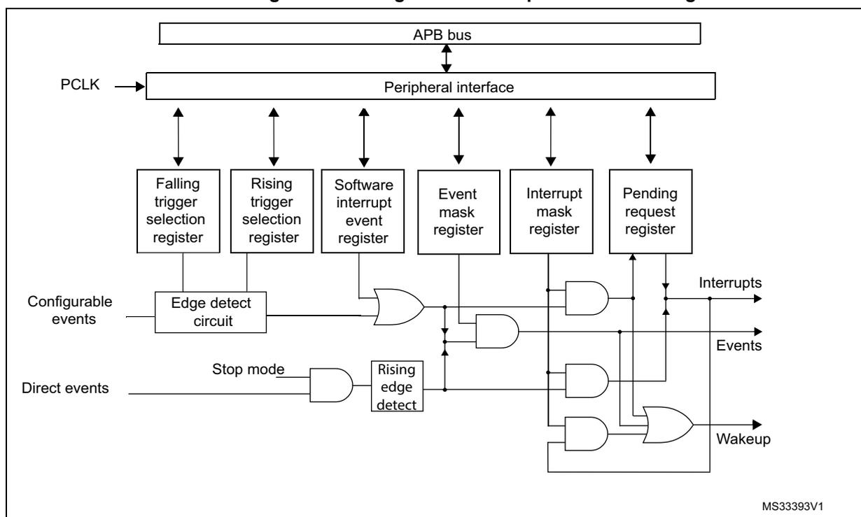
For the configurable interrupt lines, the interrupt line should be configured and enabled in order to generate an interrupt. This is done by programming the two trigger registers with the desired edge detection and by enabling the interrupt request by writing 1 to the corresponding bit in the interrupt mask register. When the selected edge occurs on the interrupt line, an interrupt request is generated. The pending bit corresponding to the interrupt line is also set. This request is cleared by writing 1 in the pending register.
For the direct interrupt lines, the interrupt is enabled by default in the interrupt mask register and there is no corresponding pending bit in the pending register.
To generate an event, the event line should be configured and enabled. This is done by programming the two trigger registers with the desired edge detection and by enabling the event request by writing 1 to the corresponding bit in the event mask register. When the
selected edge occurs on the event line, an event pulse is generated. The pending bit corresponding to the event line is not set.
For the configurable lines, an interrupt/event request can also be generated by software by writing 1 in the software interrupt/event register.
Note: The interrupts or events associated to the direct lines are triggered only when the system is in Stop mode. If the system is still running, no interrupt/event is generated by the EXTI.
15.3.1 EXTI block diagram
The extended interrupt/event block diagram is shown on Figure 35 .
Figure 35. Configurable interrupt/event block diagram
15.3.2 Wake-up event management
The devices handle external or internal events to wake up the core (WFE). The wake-up event can be generated either by:
- • enabling an interrupt in the peripheral control register but not in the NVIC, and enabling the SEVONPEND bit in the Cortex™-M4 System Control register. When the MCU resumes from WFE, the EXTI peripheral interrupt pending bit and the peripheral NVIC IRQ channel pending bit (in the NVIC interrupt clear pending register) have to be cleared
- • or by configuring an EXTI line in event mode. When the CPU resumes from WFE, it is not necessary to clear the peripheral interrupt pending bit or the NVIC IRQ channel pending bit as the pending bit corresponding to the event line is not set.
15.3.3 Peripherals asynchronous Interrupts
Some peripherals are able to generate events when the system is in run mode and also when the system is in Stop mode, allowing to wake up the system from Stop mode.
To accomplish this, the peripheral generates both a synchronized (to the system clock, e.g. APB clock) and an asynchronous version of the event. This asynchronous event is connected to an EXTI direct line.
Note: Few peripherals with wake-up from Stop capability are connected to an EXTI configurable line. In this case, the EXTI configuration is necessary to allow the wake-up from Stop mode.
15.3.4 Hardware interrupt selection
To configure a line as an interrupt source, use the following procedure:
- 1. Configure the corresponding mask bit in the EXTI_IMR register.
- 2. Configure the Trigger Selection bits of the Interrupt line (EXTI_RTSR and EXTI_FTSR).
- 3. Configure the enable and mask bits that control the NVIC IRQ channel mapped to the EXTI so that an interrupt coming from one of the EXTI lines can be correctly acknowledged.
Note: The direct lines do not require any EXTI configuration.
15.3.5 Hardware event selection
To configure a line as an event source, use the following procedure:
- 1. Configure the corresponding mask bit in the EXTI_EMR register.
- 2. Configure the Trigger Selection bits of the Event line (EXTI_RTSR and EXTI_FTSR).
15.3.6 Software interrupt/event selection
Any of the configurable lines can be configured as a software interrupt/event line. The procedure to generate a software interrupt is as follows:
- 1. Configure the corresponding mask bit (EXTI_IMR, EXTI_EMR).
- 2. Set the required bit of the software interrupt register (EXTI_SWIER).
15.4 EXTI interrupt/event line mapping
In the STM32G4 series, 42 interrupt/event lines are available. The GPIOs are connected to 16 configurable interrupt/event lines (see Figure 36 ).
Figure 36. External interrupt/event GPIO mapping
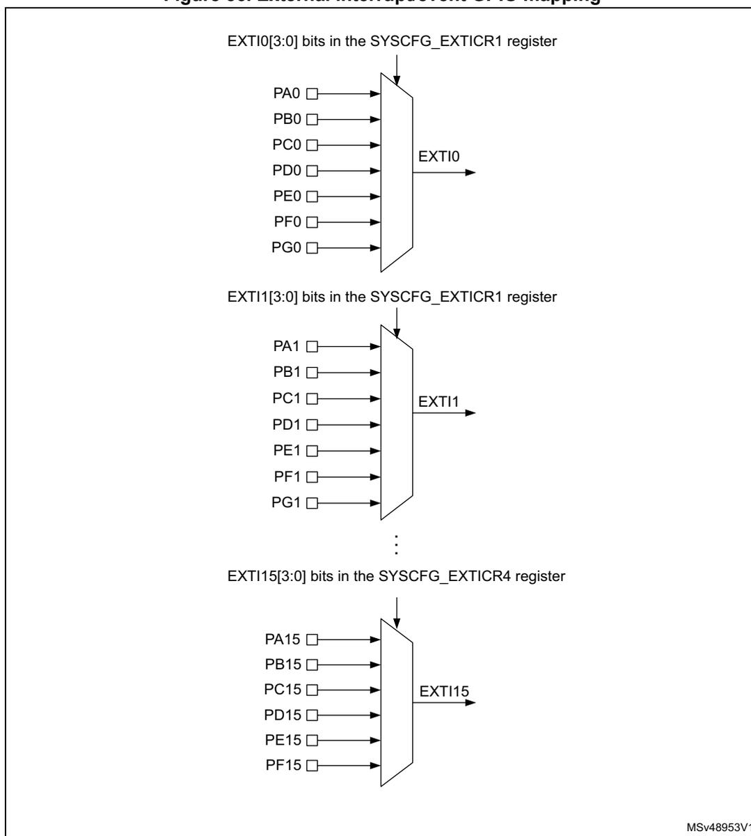
The diagram illustrates the mapping of GPIO pins to EXTI lines. It shows three examples of multiplexers:
- EXTI0: Controlled by EXTI0[3:0] bits in the SYSCFG_EXTICR1 register . Inputs: PA0, PB0, PC0, PD0, PE0, PF0, PG0. Output: EXTI0 .
- EXTI1: Controlled by EXTI1[3:0] bits in the SYSCFG_EXTICR1 register . Inputs: PA1, PB1, PC1, PD1, PE1, PF1, PG1. Output: EXTI1 .
- EXTI15: Controlled by EXTI15[3:0] bits in the SYSCFG_EXTICR4 register . Inputs: PA15, PB15, PC15, PD15, PE15, PF15. Output: EXTI15 .
Vertical ellipsis between EXTI1 and EXTI15 indicates that the same pattern repeats for all EXTI lines 0-15. The diagram is labeled with MSV48953V1 in the bottom right corner.
The EXTI lines are connected as shown in Table 101: EXTI lines connections .
Table 101. EXTI lines connections
| EXTI line | Line source | Line type |
|---|---|---|
| 0-15 | GPIO | Configurable |
| 16 | PVD | Configurable |
| 17 | RTC alarm event | Configurable |
| 18 | USB Device FS wake-up event | Direct |
| 19 | Timestamp or CSS_LSE | Configurable |
| 20 | RTC wake-up timer | Configurable |
Table 101. EXTI lines connections (continued)
| EXTI line | Line source | Line type |
|---|---|---|
| 21 | COMP1 output | Configurable |
| 22 | COMP2 output | Configurable |
| 23 | I2C1 wake-up | Direct |
| 24 | I2C2 wake-up | Direct |
| 25 | USART1 wake-up | Direct |
| 26 | USART2 wake-up | Direct |
| 27 | I2C3 wake-up | Direct |
| 28 | USART3 wake-up | Direct |
| 29 | COMP3 output | Configurable |
| 30 | COMP4 output | Configurable |
| 31 | COMP5 output | Configurable |
| 32 | COMP6 output | Configurable |
| 33 | COMP7 output | Configurable |
| 34 | UART4 wake-up | Direct |
| 35 | UART5 wake-up | Direct |
| 36 | LPUART1 wake-up | Direct |
| 37 | LPTIM1 wake-up | Direct |
| 40 | PVM1 wake-up | Configurable |
| 41 | PVM2 wake-up | Configurable |
| 42 | I2C4 wake-up | Direct |
| 43 | UCPD1 | Direct |
15.5 EXTI registers
Refer to Section 1.2 on page 74 for a list of abbreviations used in register descriptions.
The peripheral registers have to be accessed by words (32-bit).
15.5.1 Interrupt mask register 1 (EXTI_IMR1)
Address offset: 0x00
Reset value: Direct lines are set to 1, others lines are set to 0. See Table 101 .
| 31 | 30 | 29 | 28 | 27 | 26 | 25 | 24 | 23 | 22 | 21 | 20 | 19 | 18 | 17 | 16 |
|---|---|---|---|---|---|---|---|---|---|---|---|---|---|---|---|
| IM31 | IM30 | IM29 | IM28 | IM27 | IM26 | IM25 | IM24 | IM23 | IM22 | IM21 | IM20 | IM19 | IM18 | IM17 | IM16 |
| rw | rw | rw | rw | rw | rw | rw | rw | rw | rw | rw | rw | rw | rw | rw | rw |
| 15 | 14 | 13 | 12 | 11 | 10 | 9 | 8 | 7 | 6 | 5 | 4 | 3 | 2 | 1 | 0 |
| IM15 | IM14 | IM13 | IM12 | IM11 | IM10 | IM9 | IM8 | IM7 | IM6 | IM5 | IM4 | IM3 | IM2 | IM1 | IM0 |
| rw | rw | rw | rw | rw | rw | rw | rw | rw | rw | rw | rw | rw | rw | rw | rw |
Bits 31:0 IMx : Interrupt mask on line x (x = 31 to 0)
0: Interrupt request from Line x is masked
1: Interrupt request from Line x is not masked
Note: The reset value for the direct lines is set to 1 to enable the interrupt by default.
15.5.2 Event mask register 1 (EXTI_EMR1)
Address offset: 0x04
Reset value: 0x0000 0000
| 31 | 30 | 29 | 28 | 27 | 26 | 25 | 24 | 23 | 22 | 21 | 20 | 19 | 18 | 17 | 16 |
|---|---|---|---|---|---|---|---|---|---|---|---|---|---|---|---|
| EM31 | EM30 | EM29 | EM28 | EM27 | EM26 | EM25 | EM24 | EM23 | EM22 | EM21 | EM20 | EM19 | EM18 | EM17 | EM16 |
| rw | rw | rw | rw | rw | rw | rw | rw | rw | rw | rw | rw | rw | rw | rw | rw |
| 15 | 14 | 13 | 12 | 11 | 10 | 9 | 8 | 7 | 6 | 5 | 4 | 3 | 2 | 1 | 0 |
| EM15 | EM14 | EM13 | EM12 | EM11 | EM10 | EM9 | EM8 | EM7 | EM6 | EM5 | EM4 | EM3 | EM2 | EM1 | EM0 |
| rw | rw | rw | rw | rw | rw | rw | rw | rw | rw | rw | rw | rw | rw | rw | rw |
Bits 31:0 EMx : Event mask on line x (x = 31 to 0)
0: Event request from line x is masked
1: Event request from line x is not masked
15.5.3 Rising trigger selection register 1 (EXTI_RTSR1)
Address offset: 0x08
Reset value: 0x0000 0000
| 31 | 30 | 29 | 28 | 27 | 26 | 25 | 24 | 23 | 22 | 21 | 20 | 19 | 18 | 17 | 16 |
|---|---|---|---|---|---|---|---|---|---|---|---|---|---|---|---|
| RT31 | RT30 | RT29 | Res. | Res. | Res. | Res. | Res. | Res. | RT22 | RT21 | RT20 | RT19 | Res. | RT17 | RT16 |
| rw | rw | rw | rw | rw | rw | rw | rw | rw | |||||||
| 15 | 14 | 13 | 12 | 11 | 10 | 9 | 8 | 7 | 6 | 5 | 4 | 3 | 2 | 1 | 0 |
| RT15 | RT14 | RT13 | RT12 | RT11 | RT10 | RT9 | RT8 | RT7 | RT6 | RT5 | RT4 | RT3 | RT2 | RT1 | RT0 |
| rw | rw | rw | rw | rw | rw | rw | rw | rw | rw | rw | rw | rw | rw | rw | rw |
Bits 31:29 RTx : Rising trigger event configuration bit of line x (x = 31 to 29)
0: Rising trigger disabled (for Event and Interrupt) for input line
1: Rising trigger enabled (for Event and Interrupt) for input line
Bits 28:23 Reserved, must be kept at reset value.
Bits 22:19 RTx : Rising trigger event configuration bit of line x (x = 22 to 19)
0: Rising trigger disabled (for Event and Interrupt) for input line
1: Rising trigger enabled (for Event and Interrupt) for input line
Bit 18 Reserved, must be kept at reset value.
Bits 17:0 RTx : Rising trigger event configuration bit of line x (x = 17 to 0)
0: Rising trigger disabled (for Event and Interrupt) for input line
1: Rising trigger enabled (for Event and Interrupt) for input line
Note: The configurable wake-up lines are edge-triggered. No glitch must be generated on these lines. If a rising edge on a configurable interrupt line occurs during a write operation in the EXTI_RTSR register, the pending bit is not set.
Rising and falling edge triggers can be set for the same interrupt line. In this case, both generate a trigger condition.
15.5.4 Falling trigger selection register 1 (EXTI_FTSR1)
Address offset: 0x0C
Reset value: 0x0000 0000
| 31 | 30 | 29 | 28 | 27 | 26 | 25 | 24 | 23 | 22 | 21 | 20 | 19 | 18 | 17 | 16 |
|---|---|---|---|---|---|---|---|---|---|---|---|---|---|---|---|
| FT31 | FT30 | FT29 | Res. | Res. | Res. | Res. | Res. | Res. | FT22 | FT21 | FT20 | FT19 | Res. | FT17 | FT16 |
| rw | rw | rw | rw | rw | rw | rw | rw | rw | |||||||
| 15 | 14 | 13 | 12 | 11 | 10 | 9 | 8 | 7 | 6 | 5 | 4 | 3 | 2 | 1 | 0 |
| FT15 | FT14 | FT13 | FT12 | FT11 | FT10 | FT9 | FT8 | FT7 | FT6 | FT5 | FT4 | FT3 | FT2 | FT1 | FT0 |
| rw | rw | rw | rw | rw | rw | rw | rw | rw | rw | rw | rw | rw | rw | rw | rw |
Bits 31:29 FTx : Falling trigger event configuration bit of line x (x = 31 to 29)
0: Falling trigger disabled (for Event and Interrupt) for input line
1: Falling trigger enabled (for Event and Interrupt) for input line
Bits 28:23 Reserved, must be kept at reset value.
Bits 22:19 FTx : Falling trigger event configuration bit of line x (x = 22 to 19)
0: Falling trigger disabled (for Event and Interrupt) for input line
1: Falling trigger enabled (for Event and Interrupt) for input line
Bit 18 Reserved, must be kept at reset value.
Bits 17:0 FTx : Falling trigger event configuration bit of line x (x = 17 to 0)
0: Falling trigger disabled (for Event and Interrupt) for input line
1: Falling trigger enabled (for Event and Interrupt) for input line
Note: The configurable wake-up lines are edge-triggered. No glitch must be generated on these lines. If a falling edge on a configurable interrupt line occurs during a write operation to the EXTI_FTSR register, the pending bit is not set.
Rising and falling edge triggers can be set for the same interrupt line. In this case, both generate a trigger condition.
15.5.5 Software interrupt event register 1 (EXTI_SWIER1)
Address offset: 0x10
Reset value: 0x0000 0000
| 31 | 30 | 29 | 28 | 27 | 26 | 25 | 24 | 23 | 22 | 21 | 20 | 19 | 18 | 17 | 16 |
|---|---|---|---|---|---|---|---|---|---|---|---|---|---|---|---|
| SWI 31 | SWI 30 | SWI 29 | Res. | Res. | Res. | Res. | Res. | Res. | SWI 22 | SWI 21 | SWI 20 | SWI 19 | Res. | SWI 17 | SWI 16 |
| rw | rw | rw | rw | rw | rw | rw | rw | rw |
| 15 | 14 | 13 | 12 | 11 | 10 | 9 | 8 | 7 | 6 | 5 | 4 | 3 | 2 | 1 | 0 |
|---|---|---|---|---|---|---|---|---|---|---|---|---|---|---|---|
| SWI 15 | SWI 14 | SWI 13 | SWI 12 | SWI 11 | SWI 10 | SWI 9 | SWI 8 | SWI 7 | SWI 6 | SWI 5 | SWI 4 | SWI 3 | SWI 2 | SWI 1 | SWI 0 |
| rw | rw | rw | rw | rw | rw | rw | rw | rw | rw | rw | rw | rw | rw | rw | rw |
Bits 31:29 SWIx : Software interrupt on line x (x = 31 to 29)
If the interrupt is enabled on this line in the EXTI_IMR , writing 1 to this bit when it is at 0 sets the corresponding pending bit in EXTI_PR resulting in an interrupt request generation.
This bit is cleared by clearing the corresponding bit in the EXTI_PR register (by writing 1 into the bit).
Bits 28:23 Reserved, must be kept at reset value.
Bits 22: 19 SWIx : Software interrupt on line x (x = 22 to 19)
If the interrupt is enabled on this line in the EXTI_IMR , writing 1 to this bit when it is at 0 sets the corresponding pending bit in EXTI_PR resulting in an interrupt request generation.
This bit is cleared by clearing the corresponding bit in the EXTI_PR register (by writing 1 into the bit).
Bit 18 Reserved, must be kept at reset value.
Bits 17:0 SWIx : Software interrupt on line x (x = 17 to 0)
If the interrupt is enabled on this line in the EXTI_IMR , writing 1 to this bit when it is at 0 sets the corresponding pending bit in EXTI_PR resulting in an interrupt request generation.
This bit is cleared by clearing the corresponding bit of EXTI_PR (by writing 1 into the bit).
15.5.6 Pending register 1 (EXTI_PR1)
Address offset: 0x14
Reset value: 0x0000 0000
| 31 | 30 | 29 | 28 | 27 | 26 | 25 | 24 | 23 | 22 | 21 | 20 | 19 | 18 | 17 | 16 |
|---|---|---|---|---|---|---|---|---|---|---|---|---|---|---|---|
| PIF31 | PIF30 | PIF29 | Res. | Res. | Res. | Res. | Res. | Res. | PIF22 | PIF21 | PIF20 | PIF19 | Res. | PIF17 | PIF16 |
| rc_w1 | rc_w1 | rc_w1 | rc_w1 | rc_w1 | rc_w1 | rc_w1 | rc_w1 | rc_w1 | |||||||
| 15 | 14 | 13 | 12 | 11 | 10 | 9 | 8 | 7 | 6 | 5 | 4 | 3 | 2 | 1 | 0 |
| PIF15 | PIF14 | PIF13 | PIF12 | PIF11 | PIF10 | PIF9 | PIF8 | PIF7 | PIF6 | PIF5 | PIF4 | PIF3 | PIF2 | PIF1 | PIF0 |
| rc_w1 | rc_w1 | rc_w1 | rc_w1 | rc_w1 | rc_w1 | rc_w1 | rc_w1 | rc_w1 | rc_w1 | rc_w1 | rc_w1 | rc_w1 | rc_w1 | rc_w1 | rc_w1 |
Bits 31:29 PIFx : Pending interrupt flag on line x (x = 31 to 29)
0: No trigger request occurred
1: Selected trigger request occurred
This bit is set when the selected edge event arrives on the interrupt line. This bit is cleared by writing 1 to the bit.
Bits 28:23 Reserved, must be kept at reset value.
Bits 22:19 PIFx : Pending interrupt flag on line x (x = 22 to 19)
0: No trigger request occurred
1: Selected trigger request occurred
This bit is set when the selected edge event arrives on the interrupt line. This bit is cleared by writing 1 to the bit.
Bit 18 Reserved, must be kept at reset value.
Bits 17:0 PIFx : Pending interrupt flag on line x (x = 17 to 0)
0: No trigger request occurred
1: Selected trigger request occurred
This bit is set when the selected edge event arrives on the interrupt line. This bit is cleared by writing 1 to the bit.
15.5.7 Interrupt mask register 2 (EXTI_IMR2)
Address offset: 0x20
Reset value: Direct lines are set to 1, others lines are set to 0. See Table 101 .
| 31 | 30 | 29 | 28 | 27 | 26 | 25 | 24 | 23 | 22 | 21 | 20 | 19 | 18 | 17 | 16 |
|---|---|---|---|---|---|---|---|---|---|---|---|---|---|---|---|
| Res. | Res. | Res. | Res. | Res. | Res. | Res. | Res. | Res. | Res. | Res. | Res. | Res. | Res. | Res. | Res. |
| 15 | 14 | 13 | 12 | 11 | 10 | 9 | 8 | 7 | 6 | 5 | 4 | 3 | 2 | 1 | 0 |
| Res. | Res. | Res. | Res. | IM43 | IM42 | IM41 | IM40 | Res. | Res. | IM37 | IM36 | IM35 | IM34 | IM33 | IM32 |
| rw | rw | rw | rw | rw | rw | rw | rw | rw | rw |
Bits 31:12 Reserved, must be kept at reset value
Bits 11:8 IMx : Interrupt mask on line x (x = 43 to 40)
0: Interrupt request from line x is masked
1: Interrupt request from line x is not masked
Bits 7:6 Reserved, must be kept at reset value
Bits 5:0 IMx : Interrupt mask on line x (x = 37 to 32)
0: Interrupt request from line x is masked
1: Interrupt request from line x is not masked
Note: The reset value for the direct lines is set to 1 to enable the interrupt by default.
15.5.8 Event mask register 2 (EXTI_EMR2)
Address offset: 0x24
Reset value: 0x0000 0000
| 31 | 30 | 29 | 28 | 27 | 26 | 25 | 24 | 23 | 22 | 21 | 20 | 19 | 18 | 17 | 16 |
|---|---|---|---|---|---|---|---|---|---|---|---|---|---|---|---|
| Res. | Res. | Res. | Res. | Res. | Res. | Res. | Res. | Res. | Res. | Res. | Res. | Res. | Res. | Res. | Res. |
| 15 | 14 | 13 | 12 | 11 | 10 | 9 | 8 | 7 | 6 | 5 | 4 | 3 | 2 | 1 | 0 |
| Res. | Res. | Res. | Res. | EM43 | EM42 | EM41 | EM40 | Res. | Res. | EM37 | EM36 | EM35 | EM34 | EM33 | EM32 |
| rw | rw | rw | rw | rw | rw | rw | rw | rw | rw |
Bits 31:12 Reserved, must be kept at reset value.
Bits 11:8 EMx : Event mask on line x (x = 43 to 40)
0: Event request from line x is masked
1: Event request from line x is not masked
Bits 7:6 Reserved, must be kept at reset value.
Bits 5:0 EMx : Event mask on line x (x = 37 to 32)
0: Event request from line x is masked
1: Event request from line x is not masked
15.5.9 Rising trigger selection register 2 (EXTI_RTSR2)
Address offset: 0x28
Reset value: 0x0000 0000
| 31 | 30 | 29 | 28 | 27 | 26 | 25 | 24 | 23 | 22 | 21 | 20 | 19 | 18 | 17 | 16 |
|---|---|---|---|---|---|---|---|---|---|---|---|---|---|---|---|
| Res. | Res. | Res. | Res. | Res. | Res. | Res. | Res. | Res. | Res. | Res. | Res. | Res. | Res. | Res. | Res. |
| 15 | 14 | 13 | 12 | 11 | 10 | 9 | 8 | 7 | 6 | 5 | 4 | 3 | 2 | 1 | 0 |
| Res. | Res. | Res. | Res. | Res. | Res. | RT41 | RT40 | Res. | Res. | Res. | Res. | Res. | Res. | RT33 | RT32 |
| rw | rw | rw | rw |
Bits 31:10 Reserved, must be kept at reset value.
Bits 9:8 RTx : Rising trigger event configuration bit of line x (x = 40 to 41)
0: Rising trigger disabled (for Event and Interrupt) for input line
1: Rising trigger enabled (for Event and Interrupt) for input line
Bits 7:2 Reserved, must be kept at reset value.
Bits 1:0 RTx : Rising trigger event configuration bit of line x (x = 32 to 33)
0: Rising trigger disabled (for Event and Interrupt) for input line
1: Rising trigger enabled (for Event and Interrupt) for input line
Note: The configurable wake-up lines are edge-triggered. No glitch must be generated on these lines. If a rising edge on a configurable interrupt line occurs during a write operation to the EXTI_RTSR register, the pending bit is not set.
Rising and falling edge triggers can be set for the same interrupt line. In this case, both generate a trigger condition.
15.5.10 Falling trigger selection register 2 (EXTI_FTSR2)
Address offset: 0x2C
Reset value: 0x0000 0000
| 31 | 30 | 29 | 28 | 27 | 26 | 25 | 24 | 23 | 22 | 21 | 20 | 19 | 18 | 17 | 16 |
|---|---|---|---|---|---|---|---|---|---|---|---|---|---|---|---|
| Res. | Res. | Res. | Res. | Res. | Res. | Res. | Res. | Res. | Res. | Res. | Res. | Res. | Res. | Res. | Res. |
| 15 | 14 | 13 | 12 | 11 | 10 | 9 | 8 | 7 | 6 | 5 | 4 | 3 | 2 | 1 | 0 |
| Res. | Res. | Res. | Res. | Res. | Res. | FT41 | FT40 | Res. | Res. | Res. | Res. | Res. | Res. | FT33 | FT32 |
| rw | rw | rw | rw |
Bits 31:10 Reserved, must be kept at reset value.
Bits 9:8 FTx : Falling trigger event configuration bit of line x (x = 40 to 41)
0: Falling trigger disabled (for Event and Interrupt) for input line
1: Falling trigger enabled (for Event and Interrupt) for input line
Bits 7:2 Reserved, must be kept at reset value.
Bits 1:0 FTx : Falling trigger event configuration bit of line x (x = 32 to 33)
0: Falling trigger disabled (for Event and Interrupt) for input line
1: Falling trigger enabled (for Event and Interrupt) for input line
Note: The configurable wake-up lines are edge-triggered. No glitch must be generated on these lines. If a falling edge on a configurable interrupt line occurs during a write operation to the EXTI_FTSR register, the pending bit is not set.
Rising and falling edge triggers can be set for the same interrupt line. In this case, both generate a trigger condition.
15.5.11 Software interrupt event register 2 (EXTI_SWIER2)
Address offset: 0x30
Reset value: 0x0000 0000
| 31 | 30 | 29 | 28 | 27 | 26 | 25 | 24 | 23 | 22 | 21 | 20 | 19 | 18 | 17 | 16 |
|---|---|---|---|---|---|---|---|---|---|---|---|---|---|---|---|
| Res. | Res. | Res. | Res. | Res. | Res. | Res. | Res. | Res. | Res. | Res. | Res. | Res. | Res. | Res. | Res. |
| 15 | 14 | 13 | 12 | 11 | 10 | 9 | 8 | 7 | 6 | 5 | 4 | 3 | 2 | 1 | 0 |
| Res. | Res. | Res. | Res. | Res. | Res. | SWI 41 | SWI 40 | Res. | Res. | Res. | Res. | Res. | Res. | SWI 33 | SWI 32 |
| rw | rw | rw | rw |
Bits 31:10 Reserved, must be kept at reset value.
Bits 9:8 SWIx : Software interrupt on line x (x = 40 to 41)
If the interrupt is enabled on this line in EXTI_IMR, writing 1 to this bit when it is at 0 sets the corresponding pending bit of EXTI_PR resulting in an interrupt request generation.
This bit is cleared by clearing the corresponding bit of EXTI_PR (by writing 1 to the bit).
Bits 7:2 Reserved, must be kept at reset value.
Bits 1:0 SWIx : Software interrupt on line x (x = 32 to 33)
If the interrupt is enabled on this line in EXTI_IMR, writing 1 to this bit when it is at 0 sets the corresponding pending bit of EXTI_PR resulting in an interrupt request generation.
This bit is cleared by clearing the corresponding bit of EXTI_PR (by writing 1 to the bit).
15.5.12 Pending register 2 (EXTI_PR2)
Address offset: 0x34
Reset value: 0x0000 0000
| 31 | 30 | 29 | 28 | 27 | 26 | 25 | 24 | 23 | 22 | 21 | 20 | 19 | 18 | 17 | 16 |
|---|---|---|---|---|---|---|---|---|---|---|---|---|---|---|---|
| Res. | Res. | Res. | Res. | Res. | Res. | Res. | Res. | Res. | Res. | Res. | Res. | Res. | Res. | Res. | Res. |
| 15 | 14 | 13 | 12 | 11 | 10 | 9 | 8 | 7 | 6 | 5 | 4 | 3 | 2 | 1 | 0 |
| Res. | Res. | Res. | Res. | Res. | Res. | PIF41 | PIF40 | Res. | Res. | Res. | Res. | Res. | Res. | PIF33 | PIF32 |
| rc_w1 | rc_w1 | rc_w1 | rc_w1 |
Bits 31:10 Reserved, must be kept at reset value.
Bits 9:8 PIFx : Pending interrupt flag on line x (x = 40 to 41)
0: No trigger request occurred
1: Selected trigger request occurred
This bit is set when the selected edge event arrives on the interrupt line. This bit is cleared by writing 1 into the bit.
Bits 7:2 Reserved, must be kept at reset value.
Bits 1:0 PIFx : Pending interrupt flag on line x (x = 32 to 33)
0: No trigger request occurred
1: Selected trigger request occurred
This bit is set when the selected edge event arrives on the interrupt line. This bit is cleared by writing 1 into the bit.
15.5.13 EXTI register map
Table 102 gives the EXTI register map and the reset values.
Table 102. Extended interrupt/event controller register map and reset values
| Offset | Register | 31 | 30 | 29 | 28 | 27 | 26 | 25 | 24 | 23 | 22 | 21 | 20 | 19 | 18 | 17 | 16 | 15 | 14 | 13 | 12 | 11 | 10 | 9 | 8 | 7 | 6 | 5 | 4 | 3 | 2 | 1 | 0 |
|---|---|---|---|---|---|---|---|---|---|---|---|---|---|---|---|---|---|---|---|---|---|---|---|---|---|---|---|---|---|---|---|---|---|
| 0x00 | EXTI_IMR1 | IM31 | IM30 | IM29 | IM28 | IM27 | IM26 | IM25 | IM24 | IM23 | IM22 | IM21 | IM20 | IM19 | IM18 | IM17 | IM16 | IM15 | IM14 | IM13 | IM12 | IM11 | IM10 | IM9 | IM8 | IM7 | IM6 | IM5 | IM4 | IM3 | IM2 | IM1 | IM0 |
| Reset value | 1 | 1 | 1 | 1 | 1 | 1 | 1 | 1 | 1 | 0 | 0 | 0 | 0 | 0 | 1 | 0 | 0 | 0 | 0 | 0 | 0 | 0 | 0 | 0 | 0 | 0 | 0 | 0 | 0 | 0 | 0 | 0 | 0 |
| 0x04 | EXTI_EMR1 | EM31 | EM30 | EM29 | EM28 | EM27 | EM26 | EM25 | EM24 | EM23 | EM22 | EM21 | EM20 | EM19 | EM18 | EM17 | EM16 | EM15 | EM14 | EM13 | EM12 | EM11 | EM10 | EM9 | EM8 | EM7 | EM6 | EM5 | EM4 | EM3 | EM2 | EM1 | EM0 |
| Reset value | 0 | 0 | 0 | 0 | 0 | 0 | 0 | 0 | 0 | 0 | 0 | 0 | 0 | 0 | 0 | 0 | 0 | 0 | 0 | 0 | 0 | 0 | 0 | 0 | 0 | 0 | 0 | 0 | 0 | 0 | 0 | 0 | |
| 0x08 | EXTI_RTSR1 | RT31 | RT30 | RT29 | Res. | Res. | Res. | Res. | Res. | Res. | RT22 | RT21 | RT20 | RT19 | Res. | RT17 | RT16 | RT15 | RT14 | RT13 | RT12 | RT11 | RT10 | RT9 | RT8 | RT7 | RT6 | RT5 | RT4 | RT3 | RT2 | RT1 | RT0 |
| Reset value | 0 | 0 | 0 | 0 | 0 | 0 | 0 | 0 | 0 | 0 | 0 | 0 | 0 | 0 | 0 | 0 | 0 | 0 | 0 | 0 | 0 | 0 | 0 | 0 | 0 | ||||||||
| 0x0C | EXTI_FTSR1 | FT31 | FT30 | FT29 | Res. | Res. | Res. | Res. | Res. | Res. | FT22 | FT21 | FT20 | FT19 | Res. | FT17 | FT16 | FT15 | FT14 | FT13 | FT12 | FT11 | FT10 | FT9 | FT8 | FT7 | FT6 | FT5 | FT4 | FT3 | FT2 | FT1 | FT0 |
| Reset value | 0 | 0 | 0 | 0 | 0 | 0 | 0 | 0 | 0 | 0 | 0 | 0 | 0 | 0 | 0 | 0 | 0 | 0 | 0 | 0 | 0 | 0 | 0 | 0 | 0 | ||||||||
| 0x10 | EXTI_SWIER1 | SW312 | SW30 | SW29 | Res. | Res. | Res. | Res. | Res. | Res. | SW22 | SW21 | SW20 | SW19 | Res. | SW17 | SW16 | SW15 | SW14 | SW13 | SW12 | SW11 | SW10 | SW9 | SW8 | SW7 | SW6 | SW5 | SW4 | SW3 | SW2 | SW1 | SW0 |
| Reset value | 0 | 0 | 0 | 0 | 0 | 0 | 0 | 0 | 0 | 0 | 0 | 0 | 0 | 0 | 0 | 0 | 0 | 0 | 0 | 0 | 0 | 0 | 0 | 0 | 0 | ||||||||
| 0x14 | EXTI_PR1 | PIF31 | PIF30 | PIF29 | Res. | Res. | Res. | Res. | Res. | Res. | PIF22 | PIF21 | PIF20 | PIF19 | Res. | PIF17 | PIF16 | PIF15 | PIF14 | PIF13 | PIF12 | PIF11 | PIF10 | PIF9 | PIF8 | PIF7 | PIF6 | PIF5 | PIF4 | PIF3 | PIF2 | PIF1 | PIF0 |
| Reset value | 0 | 0 | 0 | 0 | 0 | 0 | 0 | 0 | 0 | 0 | 0 | 0 | 0 | 0 | 0 | 0 | 0 | 0 | 0 | 0 | 0 | 0 | 0 | 0 | 0 | ||||||||
| 0x20 | EXTI_IMR2 | Res. | Res. | Res. | Res. | Res. | Res. | Res. | Res. | Res. | Res. | Res. | Res. | Res. | Res. | Res. | Res. | Res. | Res. | Res. | Res. | IM43 | IM42 | IM41 | IM40 | Res. | Res. | IM37 | IM36 | IM35 | IM34 | IM33 | IM32 |
| Reset value | 1 | 1 | 0 | 1 | 0 | 0 | 0 | 1 | 1 | 1 | |||||||||||||||||||||||
| 0x24 | EXTI_EMR2 | Res. | Res. | Res. | Res. | Res. | Res. | Res. | Res. | Res. | Res. | Res. | Res. | Res. | Res. | Res. | Res. | Res. | Res. | Res. | Res. | EM43 | EM42 | EM41 | EM40 | Res. | Res. | EM37 | EM36 | EM35 | EM34 | EM33 | EM32 |
| Reset value | 0 | 0 | 0 | 0 | 0 | 0 | 0 | 0 | 0 | 0 | |||||||||||||||||||||||
| 0x28 | EXTI_RTSR2 | Res. | Res. | Res. | Res. | Res. | Res. | Res. | Res. | Res. | Res. | Res. | Res. | Res. | Res. | Res. | Res. | Res. | Res. | Res. | Res. | Res. | Res. | RT41 | RT40 | Res. | Res. | Res. | Res. | Res. | Res. | RT33 | RT32 |
| Reset value | 0 | 0 | 0 | 0 | |||||||||||||||||||||||||||||
| 0x2C | EXTI_FTSR2 | Res. | Res. | Res. | Res. | Res. | Res. | Res. | Res. | Res. | Res. | Res. | Res. | Res. | Res. | Res. | Res. | Res. | Res. | Res. | Res. | Res. | Res. | FT41 | FT40 | Res. | Res. | Res. | Res. | Res. | Res. | FT33 | FT32 |
| Reset value | 0 | 0 | 0 | 0 | |||||||||||||||||||||||||||||
| 0x30 | EXTI_SWIER2 | Res. | Res. | Res. | Res. | Res. | Res. | Res. | Res. | Res. | Res. | Res. | Res. | Res. | Res. | Res. | Res. | Res. | Res. | Res. | Res. | Res. | Res. | SW41 | SW40 | Res. | Res. | Res. | Res. | Res. | Res. | SW33 | SW32 |
| Reset value | 0 | 0 | 0 | 0 | |||||||||||||||||||||||||||||
| 0x34 | EXTI_PR2 | Res. | Res. | Res. | Res. | Res. | Res. | Res. | Res. | Res. | Res. | Res. | Res. | Res. | Res. | Res. | Res. | Res. | Res. | Res. | Res. | Res. | Res. | PIF41 | PIF40 | Res. | Res. | Res. | Res. | Res. | Res. | PIF33 | PIF32 |
| Reset value | 0 | 0 | 0 | 0 |
Refer to Section 2.2 on page 82 for the register boundary addresses.