15. DMA request multiplexer (DMAMUX)
15.1 Introduction
A peripheral indicates a request for DMA transfer by setting its DMA request signal. The DMA request is pending until served by the DMA controller that generates a DMA acknowledge signal, and the corresponding DMA request signal is deasserted.
In this document, the set of control signals required for the DMA request/acknowledge protocol is not explicitly shown or described, and it is referred to as DMA request line.
The DMAMUX request multiplexer enables routing a DMA request line between the peripherals and the DMA controllers of the product. The routing function is ensured by a programmable multi-channel DMA request line multiplexer. Each channel selects a unique DMA request line, unconditionally or synchronously with events from its DMAMUX synchronization inputs. The DMAMUX may also be used as a DMA request generator from programmable events on its input trigger signals.
The number of DMAMUX instances and their main characteristics are specified in Section 15.3.1 .
The assignment of DMAMUX request multiplexer inputs to the DMA request lines from peripherals and to the DMAMUX request generator outputs, the assignment of DMAMUX request multiplexer outputs to DMA controller channels, and the assignment of DMAMUX synchronizations and trigger inputs to internal and external signals depend upon product implementation. They are detailed in Section 15.3.2 .
15.2 DMAMUX main features
- • 16-channel programmable DMA request line multiplexer output
- • 4-channel DMA request generator
- • 23 trigger inputs to DMA request generator
- • 23 synchronization inputs
- • Per DMA request generator channel:
- – DMA request trigger input selector
- – DMA request counter
- – Event overrun flag for selected DMA request trigger input
- • Per DMA request line multiplexer channel output:
- – 90 input DMA request lines from peripherals
- – One DMA request line output
- – Synchronization input selector
- – DMA request counter
- – Event overrun flag for selected synchronization input
- – One event output, for DMA request chaining
- • TrustZone support:
- – Support for AHB secure and non-secure DMA transfers, independently at a channel level.
- – TrustZone-aware AHB slave port, protecting any secure resource (register, register field) from a non-secure software access, with configurable interrupt event.
- – Two secure and non-secure interrupt requests, resulting from any of the respectively secure and non-secure channels. Each channel event being caused from any of the two DMAMUX input events: trigger or synchronization overrun, associated with a respectively secure and non-secure channels.
- • Privileged / Unprivileged support:
- – Support for AHB privileged and unprivileged DMA transfers, independently, at a channel level.
- – Privileged-aware AHB slave port.
15.3 DMAMUX implementation
15.3.1 DMAMUX instantiation
DMAMUX is instantiated with the hardware configuration parameters listed in the following table.
Table 101. DMAMUX instantiation
| Feature | DMAMUX |
|---|---|
| Number of DMAMUX output request channels | 16 |
| Number of DMAMUX request generator channels | 4 |
| Number of DMAMUX request trigger inputs | 23 |
| Feature | DMAMUX |
|---|---|
| Number of DMAMUX synchronization inputs | 23 |
| Number of DMAMUX peripheral request inputs | 90 |
| DMAMUX TrustZone support | 1 |
15.3.2 DMAMUX mapping
The mapping of resources to DMAMUX is hardwired.
DMAMUX is used with DMA1 and DMA2:
- • DMAMUX channels 0 to 7 are connected to DMA1 channels 1 to 8
- • DMAMUX channels 8 to 15 are connected to DMA2 channels 1 to 8
| DMA request MUX input | Resource | DMA request MUX input | Resource | DMA request MUX input | Resource |
|---|---|---|---|---|---|
| 1 | dmamux_req_gen0 | 44 | TIM1_CH3 | 87 | DFSDM1_FLT1 |
| 2 | dmamux_req_gen1 | 45 | TIM1_CH4 | 88 | DFSDM1_FLT2 |
| 3 | dmamux_req_gen2 | 46 | TIM1_UP | 89 | DFSDM1_FLT3 |
| 4 | dmamux_req_gen3 | 47 | TIM1_TRIG | 90 | AES_IN |
| 5 | ADC1 | 48 | TIM1_COM | 91 | AES_OUT |
| 6 | ADC2 | 49 | TIM8_CH1 | 92 | HASH_IN |
| 7 | DAC1 | 50 | TIM8_CH2 | 93 | USBPD_TX |
| 8 | DAC2 | 51 | TIM8_CH3 | 94 | USBPD_RX |
| 9 | TIM6_UP | 52 | TIM8_CH4 | 95 | Reserved |
| 10 | TIM7_UP | 53 | TIM8_UP | 96 | Reserved |
| 11 | SPI1_RX | 54 | TIM8_TRIG | 97 | Reserved |
| 12 | SPI1_TX | 55 | TIM8_COM | 98 | Reserved |
| 13 | SPI2_RX | 56 | TIM2_CH1 | 99 | Reserved |
| 14 | SPI2_TX | 57 | TIM2_CH2 | 100 | Reserved |
| 15 | SPI3_RX | 58 | TIM2_CH3 | 101 | Reserved |
| 16 | SPI3_TX | 59 | TIM2_CH4 | 102 | Reserved |
| 17 | I2C1_RX | 60 | TIM2_UP | 103 | Reserved |
| 18 | I2C1_TX | 61 | TIM3_CH1 | 104 | Reserved |
| 19 | I2C2_RX | 62 | TIM3_CH2 | 105 | Reserved |
| 20 | I2C2_TX | 63 | TIM3_CH3 | 106 | Reserved |
| 21 | I2C3_RX | 64 | TIM3_CH4 | 107 | Reserved |
| 22 | I2C3_TX | 65 | TIM3_UP | 108 | Reserved |
| 23 | I2C4_RX | 66 | TIM3_TRIG | 109 | Reserved |
Table 102. DMAMUX: assignment of multiplexer inputs to resources (continued)
| DMA request MUX input | Resource | DMA request MUX input | Resource | DMA request MUX input | Resource |
|---|---|---|---|---|---|
| 24 | I2C4_TX | 67 | TIM4_CH1 | 110 | Reserved |
| 25 | USART1_RX | 68 | TIM4_CH2 | 111 | Reserved |
| 26 | USART1_TX | 69 | TIM4_CH3 | 112 | Reserved |
| 27 | USART2_RX | 70 | TIM4_CH4 | 113 | Reserved |
| 28 | USART2_TX | 71 | TIM4_UP | 114 | Reserved |
| 29 | USART3_RX | 72 | TIM5_CH1 | 115 | Reserved |
| 30 | USART3_TX | 73 | TIM5_CH2 | 116 | Reserved |
| 31 | UART4_RX | 74 | TIM5_CH3 | 117 | Reserved |
| 32 | UART4_TX | 75 | TIM5_CH4 | 118 | Reserved |
| 33 | UART5_RX | 76 | TIM5_UP | 119 | Reserved |
| 34 | UART5_TX | 77 | TIM5_TRIG | 120 | Reserved |
| 35 | LPUART1_RX | 78 | TIM15_CH1 | 121 | Reserved |
| 36 | LPUART1_TX | 79 | TIM15_UP | 122 | Reserved |
| 37 | SAI1_A | 80 | TIM15_TRIG | 123 | Reserved |
| 38 | SAI1_B | 81 | TIM15_COM | 124 | Reserved |
| 39 | SAI2_A | 82 | TIM16_CH1 | 125 | Reserved |
| 40 | SAI2_B | 83 | TIM16_UP | 126 | Reserved |
| 41 | OCTOSPI1 | 84 | TIM17_CH1 | 127 | Reserved |
| 42 | TIM1_CH1 | 85 | TIM17_UP | - | - |
| 43 | TIM1_CH2 | 86 | DFSDM1_FLT0 | - | - |
Table 103. DMAMUX: assignment of trigger inputs to resources
| Trigger input | Resource | Trigger input | Resource |
|---|---|---|---|
| 0 | EXTI LINE0 | 16 | dmamux_evt0 |
| 1 | EXTI LINE1 | 17 | dmamux_evt1 |
| 2 | EXTI LINE2 | 18 | dmamux_evt2 |
| 3 | EXTI LINE3 | 19 | dmamux_evt3 |
| 4 | EXTI LINE4 | 20 | LPTIM1_OUT |
| 5 | EXTI LINE5 | 21 | LPTIM2_OUT |
| 6 | EXTI LINE6 | 22 | LPTIM3_OUT |
| 7 | EXTI LINE7 | 23 | Reserved |
| 8 | EXTI LINE8 | 24 | Reserved |
| 9 | EXTI LINE9 | 25 | Reserved |
| 10 | EXTI LINE10 | 26 | Reserved |
| 11 | EXTI LINE11 | 27 | Reserved |
| 12 | EXTI LINE12 | 28 | Reserved |
| Trigger input | Resource | Trigger input | Resource |
|---|---|---|---|
| 13 | EXTI LINE13 | 29 | Reserved |
| 14 | EXTI LINE14 | 30 | Reserved |
| 15 | EXTI LINE15 | 31 | Reserved |
| Sync. input | Resource | Sync. input | Resource |
|---|---|---|---|
| 0 | EXTI LINE0 | 16 | dmamux_evt0 |
| 1 | EXTI LINE1 | 17 | dmamux_evt1 |
| 2 | EXTI LINE2 | 18 | dmamux_evt2 |
| 3 | EXTI LINE3 | 19 | dmamux_evt3 |
| 4 | EXTI LINE4 | 20 | LPTIM1_OUT |
| 5 | EXTI LINE5 | 21 | LPTIM2_OUT |
| 6 | EXTI LINE6 | 22 | LPTIM3_OUT |
| 7 | EXTI LINE7 | 23 | Reserved |
| 8 | EXTI LINE8 | 24 | Reserved |
| 9 | EXTI LINE9 | 25 | Reserved |
| 10 | EXTI LINE10 | 26 | Reserved |
| 11 | EXTI LINE11 | 27 | Reserved |
| 12 | EXTI LINE12 | 28 | Reserved |
| 13 | EXTI LINE13 | 29 | Reserved |
| 14 | EXTI LINE14 | 30 | Reserved |
| 15 | EXTI LINE15 | 31 | Reserved |
15.4 DMAMUX functional description
15.4.1 DMAMUX block diagram
Figure 44 shows the DMAMUX block diagram.
Figure 44. DMAMUX block diagram
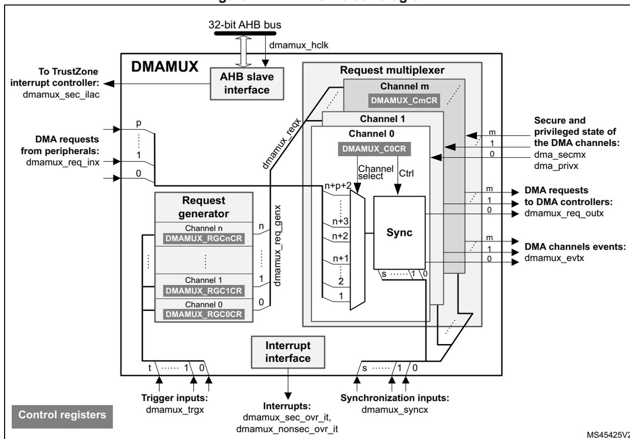
DMAMUX features two main sub-blocks: the request line multiplexer and the request line generator.
The implementation assigns:
- • DMAMUX request multiplexer sub-block inputs (dmamux_reqx) from peripherals (dmamux_req_inx) and from channels of the DMAMUX request generator sub-block (dmamux_req_genx)
- • DMAMUX request outputs to channels of DMA controllers (dmamux_req_outx)
- • Internal or external signals to DMA request trigger inputs (dmamux_trgx)
- • Internal or external signals to synchronization inputs (dmamux_syncx)
15.4.2 DMAMUX signals
Table 105 lists the DMAMUX signals.
Table 105. DMAMUX signals
| Signal name | Description |
|---|---|
| dmamux_hclk | DMAMUX AHB clock |
| dmamux_req_inx | DMAMUX DMA request line inputs from peripherals |
| dmamux_trgx | DMAMUX DMA request triggers inputs (to request generator sub-block) |
| dmamux_req_genx | DMAMUX request generator sub-block channels outputs |
| dmamux_reqx | DMAMUX request multiplexer sub-block inputs (from peripheral requests and request generator channels) |
| dmamux_syncx | DMAMUX synchronization inputs (to request multiplexer sub-block) |
| dmamux_req_outx | DMAMUX requests outputs (to DMA controllers) |
| dma_secmx | Secure mode of each DMA controller request channel |
| dma_privx | Privileged mode of each DMA controller request channel |
| dmamux_evt_x | DMAMUX events outputs |
| dmamux_non_sec_ovr_it | DMAMUX non-secure overrun interrupts |
| dmamux_sec_ovr_it | DMAMUX secure overrun interrupts |
| dmamux_illegal_access_it | DMAMUX security illegal access output (to TrustZone interrupt controller) |
15.4.3 DMAMUX channels
A DMAMUX channel is a request multiplexer channel that can include, depending upon the selected input of the request multiplexer, an additional DMAMUX request generator channel.
A DMAMUX request multiplexer channel is connected and dedicated to a single channel of DMA controller(s).
Channel configuration procedure
Follow the sequence below to configure a DMAMUX x channel and the related DMA channel y:
- 1. Set to secure or non-secure the DMA channel y by a secure write access to the secure control bit of the DMA channel y configuration register, and set to privileged or unprivileged the DMA channel y by a privileged write access to the privileged control bit of the DMA channel y configuration register.
- 2. Set and configure completely the DMA channel y, except enabling the channel y.
- 3. Set and configure completely the related DMAMUX y channel.
- 4. Last, activate the DMA channel y by setting the EN bit in the DMA y channel register.
15.4.4 DMAMUX secure/non-secure channels
The DMAMUX is a security-aware peripheral compliant with the TrustZone hardware architecture, partitioning all its resources so that they exist in one of the two worlds: the secure world and the normal/non-secure world, at any given time.
The DMAMUX security is controlled by software at channel level. Any DMAMUX channel is in secure or non-secure state, as configured by the secure register bit of the associated channel of the DMA controller(s).
Note: A DMA controller(s) channel must be first configured as secure or non-secure, before the configuration of the connected DMAMUX channel.
Note: A secure software is able to access any DMAMUX register, whatever secure or non-secure. A non-secure software is restricted to access only non-secure DMAMUX register or non-secure register fields.
A secure read/write access is a read/write transaction on AHB slave with the signal HNONSEC = 0 (at the clock cycle of the address sampling). On the contrary, a non-secure read/write access is a read/write transaction on AHB slave with the signal HNONSEC = 1. When a channel is configured in secure mode, its configuration register fields become secure resources, meaning that:
- • A non-secure read access to a (secure register) field is forced to return 0.
- • A non-secure write access to a (secure register) field has no impact.
Additionally, an illegal access signal is generated, as a pulse, to the TrustZone interrupt controller, when a non-secure software attempts to access a secure DMAMUX register:
- • DMAMUX_CxCR if the request multiplexer channel x is secure.
- • DMAMUX_RGxCR if the request generator channel x is secure.
Note: The secure illegal access signal is never asserted on a non-secure access to the global interrupt status and clear registers, even despite all the DMAMUX channels are set as secure.
15.4.5 DMAMUX privileged / unprivileged channels
The DMAMUX is aware of the privileged or unprivileged state of a given DMA connected channel, and manages consequently its DMAMUX requested channel.
Note: A DMA controller(s) channel must be first configured as privileged or unprivileged, before the configuration of the connected DMAMUX channel.
Note: A privileged software is able to access any DMAMUX register, privileged or unprivileged. An unprivileged software is restricted to access only unprivileged DMAMUX register or register fields.
When a privileged software configures a DMA channel x either as privileged, an unprivileged software is not able to access (write is ignored, read returns zero) the related DMAMUX channel registers or register fields.
15.4.6 DMAMUX request line multiplexer
The DMAMUX request multiplexer with its multiple channels ensures the actual routing of DMA request/acknowledge control signals, named DMA request lines.
Each DMA request line is connected in parallel to all the channels of the DMAMUX request line multiplexer.
A DMA request is sourced either from the peripherals, or from the DMAMUX request generator.
The DMAMUX request line multiplexer channel x selects the DMA request line number as configured by the DMAREQ_ID field in the DMAMUX_CxCR register.
Note: The null value in the field DMAREQ_ID corresponds to no DMA request line selected.
Caution: A same non-null DMAREQ_ID cannot be programmed to different x and y DMAMUX request multiplexer channels (via DMAMUX_CxCR and DMAMUX_CyCR), except when the application guarantees that the two connected DMA channels are not simultaneously active.
On top of the DMA request selection, the synchronization mode and/or the event generation may be configured and enabled, if required.
Synchronization mode and channel event generation
Each DMAMUX request line multiplexer channel x can be individually synchronized by setting the synchronization enable (SE) bit in the DMAMUX_CxCR register.
DMAMUX has multiple synchronization inputs. The synchronization inputs are connected in parallel to all the channels of the request multiplexer.
The synchronization input is selected via the SYNC_ID field in the DMAMUX_CxCR register of a given channel x.
When a channel is in this synchronization mode, the selected input DMA request line is propagated to the multiplexer channel output, once a programmable rising/falling edge is detected on the selected input synchronization signal, via the SPOL[1:0] field of the DMAMUX_CxCR register.
Additionally, internally to the DMAMUX request multiplexer, there is a programmable DMA request counter, which can be used for the channel request output generation, and for an event generation. An event generation on the channel x output is enabled through the EGE bit (event generation enable) of the DMAMUX_CxCR register.
As shown in Figure 46 , upon the detected edge of the synchronization input, the pending selected input DMA request line is connected to the DMAMUX multiplexer channel x output.
Note: If a synchronization event occurs while there is no pending selected input DMA request line, it is discarded. The following asserted input request lines is not connected to the DMAMUX multiplexer channel output until a synchronization event occurs again.
From this point on, each time the connected DMAMUX request is served by the DMA controller (a served request is deasserted), the DMAMUX request counter is decremented. At its underrun, the DMA request counter is automatically loaded with the value in the NBREQ field of the DMAMUX_CxCR register and the input DMA request line is disconnected from the multiplexer channel x output.
Thus, the number of DMA requests transferred to the multiplexer channel x output following a detected synchronization event, is equal to the value in the NBREQ field, plus one.
Note: The NBREQ field value can be written by software only when both synchronization enable bit (SE) and event generation enable bit (EGE) of the corresponding multiplexer channel x are disabled.
Figure 45. Synchronization mode of the DMAMUX request line multiplexer channel
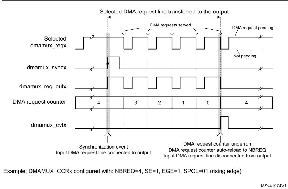
Example: DMAMUX_CCRx configured with: NBREQ=4, SE=1, EGE=1, SPOL=01 (rising edge)
MSv41974V1
Figure 46. Event generation of the DMA request line multiplexer channel
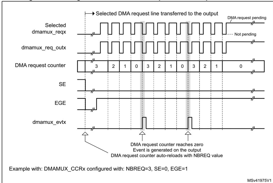
Example with: DMAMUX_CCRx configured with: NBREQ=3, SE=0, EGE=1
MSv41975V1
If EGE is enabled, the multiplexer channel generates a channel event, as a pulse of one AHB clock cycle, when its DMA request counter is automatically reloaded with the value of the programmed NBREQ field, as shown in Figure 45 and Figure 46.
Note: If EGE is enabled and NBREQ = 0, an event is generated after each served DMA request.
Note: A synchronization event (edge) is detected if the state following the edge remains stable for more than two AHB clock cycles.
Upon writing into DMAMUX_CxCR register, the synchronization events are masked during three AHB clock cycles.
Synchronization overrun and interrupt
If a new synchronization event occurs before the request counter underrun (the internal request counter programmed via the NBREQ field of the DMAMUX_CxCR register), the synchronization overrun flag bit SOFx is set in the DMAMUX_CSR register.
Note: The request multiplexer channel x synchronization must be disabled (DMAMUX_CxCR.SE = 0) when the use of the related channel of the DMA controller is completed. Else, upon a new detected synchronization event, there is a synchronization overrun due to the absence of a DMA acknowledge (that is, no served request) received from the DMA controller.
The overrun flag SOFx is reset by setting the associated clear synchronization overrun flag bit CSOFx in the DMAMUX_CCFR register.
Setting the synchronization overrun flag generates an interrupt if the synchronization overrun interrupt enable bit SOIE is set in the DMAMUX_CxCR register.
15.4.7 DMAMUX request generator
The DMAMUX request generator produces DMA requests following trigger events on its DMA request trigger inputs.
The DMAMUX request generator has multiple channels. DMA request trigger inputs are connected in parallel to all channels.
The outputs of DMAMUX request generator channels are inputs to the DMAMUX request line multiplexer.
Each DMAMUX request generator channel x has an enable bit GE (generator enable) in the corresponding DMAMUX_RGxCR register.
The DMA request trigger input for the DMAMUX request generator channel x is selected through the SIG_ID (trigger signal ID) field in the corresponding DMAMUX_RGxCR register.
Trigger events on a DMA request trigger input can be rising edge, falling edge or either edge. The active edge is selected through the GPOL (generator polarity) field in the corresponding DMAMUX_RGxCR register.
Upon the trigger event, the corresponding generator channel starts generating DMA requests on its output. Each time the DMAMUX generated request is served by the connected DMA controller (a served request is deasserted), a built-in (inside the DMAMUX request generator) DMA request counter is decremented. At its underrun, the request generator channel stops generating DMA requests and the DMA request counter is automatically reloaded to its programmed value upon the next trigger event.
Thus, the number of DMA requests generated after the trigger event is GNBREQ + 1.
Note: The GNBREQ field value can be written by software only when the enable GE bit of the corresponding generator channel x is disabled.
There is no hardware write protection.
A trigger event (edge) is detected if the state following the edge remains stable for more than two AHB clock cycles.
Upon writing into DMAMUX_RGxCR register, the trigger events are masked during three AHB clock cycles.
Trigger overrun and interrupt
If a new DMA request trigger event occurs before the DMAMUX request generator counter underrun (the internal counter programmed via the GNBREQ field of the DMAMUX_RGxCR register), and if the request generator channel x was enabled via GE, then the request trigger event overrun flag bit OFx is asserted by the hardware in the DMAMUX_RGSR register.
Note: The request generator channel x must be disabled (DMAMUX_RGxCR.GE = 0) when the usage of the related channel of the DMA controller is completed. Else, upon a new detected trigger event, there is a trigger overrun due to the absence of an acknowledge (that is, no served request) received from the DMA.
The overrun flag OFx is reset by setting the associated clear overrun flag bit COFx in the DMAMUX_RGCFR register.
Setting the DMAMUX request trigger overrun flag generates an interrupt if the DMA request trigger event overrun interrupt enable bit OIE is set in the DMAMUX_RGxCR register.
15.5 DMAMUX interrupts
An interrupt can be generated upon:
- • a synchronization event overrun in each DMA request line multiplexer channel
- • a trigger event overrun in each DMA request generator channel
For each case, per-channel individual interrupt enable, status, and clear flag register bits are available. As a consequence, there are mixed secure and non-secure status and clear flag bit fields inside a same global status and clear flag interrupt register, depending on the security of the considered DMAMUX channel.
There are two different secure and non-secure interrupt signals that may be generated, depending on the security of the DMAMUX channel.
Table 106. DMAMUX interrupts
| Interrupt signal | Interrupt event | Event flag | Clear bit | Enable bit |
|---|---|---|---|---|
| dmamux_nonsec_ovr_it | Synchronization event overrun on a non-secure channel x of the DMAMUX request line multiplexer | SOFx | CSOFx | SOIE |
| Trigger event overrun on a non-secure channel x of the DMAMUX request generator | OFx | COFx | OIE |
Table 106. DMAMUX interrupts (continued)
| Interrupt signal | Interrupt event | Event flag | Clear bit | Enable bit |
|---|---|---|---|---|
| dmamux_sec_ovr_it | Synchronization event overrun on a secure channel x of the DMAMUX request line multiplexer | SOFx | CSOFx | SOIE |
| Trigger event overrun on a secure channel x of the DMAMUX request generator | OFx | COFx | OIE |
15.6 DMAMUX registers
Refer to the table containing register boundary addresses for the DMAMUX base address.
DMAMUX registers may be accessed per byte (8-bit), half-word (16-bit), or word (32-bit). The address must be aligned with the data size.
15.6.1 DMAMUX request line multiplexer channel x configuration register (DMAMUX_CxCR)
Address offset: 0x000 + 0x04 * x (x = 0 to 15)
Reset value: 0x0000 0000
This register must be written by a non-secure or secure write, according to the secure mode of the considered DMAMUX request line multiplexer channel x, depending on the secure mode bit of the connected DMA controller channel y. This assumes that the DMAMUX x channel output is connected to the y channel of the DMA (refer to the DMAMUX mapping implementation section).
This register must be accessed by a privileged or unprivileged read/write, according to the privileged mode of the considered DMAMUX request line multiplexer channel x, depending on the privileged control bit of the connected DMA controller channel y. This assumes that the DMAMUX x channel output is connected to the y channel of the DMA (refer to the DMAMUX mapping implementation section).
| 31 | 30 | 29 | 28 | 27 | 26 | 25 | 24 | 23 | 22 | 21 | 20 | 19 | 18 | 17 | 16 |
|---|---|---|---|---|---|---|---|---|---|---|---|---|---|---|---|
| Res. | Res. | Res. | SYNC_ID[4:0] | NBREQ[4:0] | SPOL[1:0] | SE | |||||||||
| rw | rw | rw | rw | rw | rw | rw | rw | rw | rw | rw | rw | rw | |||
| 15 | 14 | 13 | 12 | 11 | 10 | 9 | 8 | 7 | 6 | 5 | 4 | 3 | 2 | 1 | 0 |
|---|---|---|---|---|---|---|---|---|---|---|---|---|---|---|---|
| Res. | Res. | Res. | Res. | Res. | Res. | EGE | SOIE | Res. | DMAREQ_ID[6:0] | ||||||
| rw | rw | rw | rw | rw | rw | rw | rw | rw | |||||||
Bits 31:29 Reserved, must be kept at reset value.
Bits 28:24 SYNC_ID[4:0] : Synchronization identification
Selects the synchronization input (see Table 104: DMAMUX: assignment of synchronization inputs to resources ).
Bits 23:19 NBREQ[4:0] : Number of DMA requests minus 1 to forward
Defines the number of DMA requests to forward to the DMA controller after a synchronization event, and/or the number of DMA requests before an output event is generated.
This field must only be written when both SE and EGE bits are low.
Bits 18:17 SPOL[1:0] : Synchronization polarity
Defines the edge polarity of the selected synchronization input:
00: No event (no synchronization, no detection).
01: Rising edge
10: Falling edge
11: Rising and falling edges
Bit 16 SE : Synchronization enable
0: Synchronization disabled
1: Synchronization enabled
Bits 15:10 Reserved, must be kept at reset value.
Bit 9 EGE : Event generation enable
0: Event generation disabled
1: Event generation enabled
Bit 8 SOIE : Synchronization overrun interrupt enable
0: Interrupt disabled
1: Interrupt enabled
Bit 7 Reserved, must be kept at reset value.
Bits 6:0 DMAREQ_ID[6:0] : DMA request identification
Selects the input DMA request. See the DMAMUX table about assignments of multiplexer inputs to resources.
15.6.2 DMAMUX request line multiplexer interrupt channel status register (DMAMUX_CSR)
Address offset: 0x080
Reset value: 0x0000 0000
This register must be accessed at bit level by a non-secure or secure read, according to the secure mode of the considered DMAMUX request line multiplexer channel x, depending on the secure mode bit of the connected DMA controller channel y, and considering that the DMAMUX x channel output is connected to the y channel of the DMA (refer to the DMAMUX mapping implementation section).
| 31 | 30 | 29 | 28 | 27 | 26 | 25 | 24 | 23 | 22 | 21 | 20 | 19 | 18 | 17 | 16 |
|---|---|---|---|---|---|---|---|---|---|---|---|---|---|---|---|
| Res. | Res. | Res. | Res. | Res. | Res. | Res. | Res. | Res. | Res. | Res. | Res. | Res. | Res. | Res. | Res. |
| 15 | 14 | 13 | 12 | 11 | 10 | 9 | 8 | 7 | 6 | 5 | 4 | 3 | 2 | 1 | 0 |
| SOF15 | SOF14 | SOF13 | SOF12 | SOF11 | SOF10 | SOF9 | SOF8 | SOF7 | SOF6 | SOF5 | SOF4 | SOF3 | SOF2 | SOF1 | SOF0 |
| r | r | r | r | r | r | r | r | r | r | r | r | r | r | r | r |
Bits 31:16 Reserved, must be kept at reset value.
Bits 15:0 SOF[15:0] : Synchronization overrun event flag
The flag is set when a synchronization event occurs on a DMA request line multiplexer channel x, while the DMA request counter value is lower than NBREQ.
The flag is cleared by writing 1 to the corresponding CSOFx bit in DMAMUX_CCFR register.
15.6.3 DMAMUX request line multiplexer interrupt channel clear flag register (DMAMUX_CCFR)
Address offset: 0x084
Reset value: 0x0000 0000
This register must be written at bit level by a non-secure or secure write, according to the secure mode of the considered DMAMUX request line multiplexer channel x, depending on the secure control bit of the connected DMA controller channel y, and considering that the DMAMUX x channel output is connected to the y channel of the DMA (refer to the DMAMUX mapping implementation section).
This register must be written at bit level by an unprivileged or privileged write, according to the privileged mode of the considered DMAMUX request line multiplexer channel x,
depending on the privileged control bit of the connected DMA controller channel y, and considering that the DMAMUX x channel output is connected to the y channel of the DMA (refer to the DMAMUX mapping implementation section).
| 31 | 30 | 29 | 28 | 27 | 26 | 25 | 24 | 23 | 22 | 21 | 20 | 19 | 18 | 17 | 16 |
|---|---|---|---|---|---|---|---|---|---|---|---|---|---|---|---|
| Res. | Res. | Res. | Res. | Res. | Res. | Res. | Res. | Res. | Res. | Res. | Res. | Res. | Res. | Res. | Res. |
| 15 | 14 | 13 | 12 | 11 | 10 | 9 | 8 | 7 | 6 | 5 | 4 | 3 | 2 | 1 | 0 |
| CSOF 15 | CSOF 14 | CSOF 13 | CSOF 12 | CSOF 11 | CSOF 10 | CSOF 9 | CSOF 8 | CSOF 7 | CSOF 6 | CSOF 5 | CSOF 4 | CSOF 3 | CSOF 2 | CSOF 1 | CSOF 0 |
| w | w | w | w | w | w | w | w | w | w | w | w | w | w | w | w |
Bits 31:16 Reserved, must be kept at reset value.
Bits 15:0 CSOF[15:0] : Clear synchronization overrun event flag
Writing 1 in each bit clears the corresponding overrun flag SOFx in the DMAMUX_CSR register.
15.6.4 DMAMUX request generator channel x configuration register (DMAMUX_RGxCR)
Address offset: 0x100 + 0x04 * x (x = 0 to 3)
Reset value: 0x0000 0000
This register must be written by a non-secure or secure write, according to the secure mode of the considered DMAMUX request line multiplexer channel y it is assigned to, and considering that the DMAMUX request generator x channel output is selected by the y channel of the DMAMUX request line channel (refer to DMAMUX_CyCR.DMAREQ_ID[7:0] and to the DMAMUX mapping implementation section).
This register must be written by an unprivileged or privileged write, according to the privileged mode of the considered DMAMUX request line multiplexer channel y it is assigned to, and considering that the DMAMUX request generator x channel output is selected by the y channel of the DMAMUX request line channel (refer to DMAMUX_CyCR.DMAREQ_ID[7:0] and to the DMAMUX mapping implementation section).
| 31 | 30 | 29 | 28 | 27 | 26 | 25 | 24 | 23 | 22 | 21 | 20 | 19 | 18 | 17 | 16 |
|---|---|---|---|---|---|---|---|---|---|---|---|---|---|---|---|
| Res. | Res. | Res. | Res. | Res. | Res. | Res. | Res. | GNBREQ[4:0] | GPOL[1:0] | GE | |||||
| rw | rw | rw | rw | rw | rw | rw | rw | ||||||||
| 15 | 14 | 13 | 12 | 11 | 10 | 9 | 8 | 7 | 6 | 5 | 4 | 3 | 2 | 1 | 0 |
| Res. | Res. | Res. | Res. | Res. | Res. | Res. | OIE | Res. | Res. | Res. | SIG_ID[4:0] | ||||
| rw | rw | rw | rw | rw | rw | ||||||||||
Bits 31:24 Reserved, must be kept at reset value.
Bits 23:19 GNBREQ[4:0] : Number of DMA requests to be generated (minus 1)
Defines the number of DMA requests to be generated after a trigger event. The actual number of generated DMA requests is GNBREQ +1.
Note: This field must be written only when GE bit is disabled.
- Bits 18:17
GPOL[1:0]
: DMA request generator trigger polarity
Defines the edge polarity of the selected trigger input
00: No event, i.e. no trigger detection nor generation.
01: Rising edge
10: Falling edge
11: Rising and falling edges - Bit 16
GE
: DMA request generator channel x enable
0: DMA request generator channel x disabled
1: DMA request generator channel x enabled - Bits 15:9 Reserved, must be kept at reset value.
- Bit 8
OIE
: Trigger overrun interrupt enable
0: Interrupt on a trigger overrun event occurrence is disabled
1: Interrupt on a trigger overrun event occurrence is enabled - Bits 7:5 Reserved, must be kept at reset value.
- Bits 4:0
SIG_ID[4:0]
: Signal identification
Selects the DMA request trigger input used for the channel x of the DMA request generator
15.6.5 DMAMUX request generator interrupt status register (DMAMUX_RGSR)
Address offset: 0x140
Reset value: 0x0000 0000
This register must be accessed at bit level by a non-secure or secure read, according to the secure mode of the considered DMAMUX request line multiplexer channel x, depending on the secure mode bit of the connected DMA controller channel y, and considering that the DMAMUX x channel output is connected to the y channel of the DMA (refer to the DMAMUX mapping implementation section).
This register must be accessed at bit level by an unprivileged or privileged read, according to the privileged mode of the considered DMAMUX request line multiplexer channel x, depending on the privileged control bit of the connected DMA controller channel y, and considering that the DMAMUX x channel output is connected to the y channel of the DMA (refer to the DMAMUX mapping implementation section).
| 31 | 30 | 29 | 28 | 27 | 26 | 25 | 24 | 23 | 22 | 21 | 20 | 19 | 18 | 17 | 16 |
|---|---|---|---|---|---|---|---|---|---|---|---|---|---|---|---|
| Res. | Res. | Res. | Res. | Res. | Res. | Res. | Res. | Res. | Res. | Res. | Res. | Res. | Res. | Res. | Res. |
| 15 | 14 | 13 | 12 | 11 | 10 | 9 | 8 | 7 | 6 | 5 | 4 | 3 | 2 | 1 | 0 |
| Res. | Res. | Res. | Res. | Res. | Res. | Res. | Res. | Res. | Res. | Res. | Res. | OF3 | OF2 | OF1 | OF0 |
| r | r | r | r |
Bits 31:4 Reserved, must be kept at reset value.
Bits 3:0 OF[3:0] : Trigger overrun event flag
The flag is set when a new trigger event occurs on DMA request generator channel x, before the request counter underrun (the internal request counter programmed via the GNBREQ field of the DMAMUX_RGxCR register).
The flag is cleared by writing 1 to the corresponding COFx bit in the DMAMUX_RGCFR register.
15.6.6 DMAMUX request generator interrupt clear flag register (DMAMUX_RGCFR)
Address offset: 0x144
Reset value: 0x0000 0000
This register must be written at bit level by a non-secure or secure write, according to the secure mode of the considered DMAMUX request line multiplexer channel y it is assigned to, and considering that the DMAMUX request generator x channel output is selected by the y channel of the DMAMUX request line channel (refer to DMAMUX_CyCR.DMAREQ_ID[7:0] and to the DMAMUX mapping implementation section).
This register must be written at bit level by an unprivileged or privileged write, according to the privileged mode of the considered DMAMUX request line multiplexer channel y it is assigned to, and considering that the DMAMUX request generator x channel output is selected by the y channel of the DMAMUX request line channel (refer to DMAMUX_CyCR.DMAREQ_ID[7:0] and to the DMAMUX mapping implementation section).
| 31 | 30 | 29 | 28 | 27 | 26 | 25 | 24 | 23 | 22 | 21 | 20 | 19 | 18 | 17 | 16 |
|---|---|---|---|---|---|---|---|---|---|---|---|---|---|---|---|
| Res. | Res. | Res. | Res. | Res. | Res. | Res. | Res. | Res. | Res. | Res. | Res. | Res. | Res. | Res. | Res. |
| 15 | 14 | 13 | 12 | 11 | 10 | 9 | 8 | 7 | 6 | 5 | 4 | 3 | 2 | 1 | 0 |
| Res. | Res. | Res. | Res. | Res. | Res. | Res. | Res. | Res. | Res. | Res. | Res. | COF3 | COF2 | COF1 | COF0 |
| w | w | w | w |
Bits 31:4 Reserved, must be kept at reset value.
Bits 3:0 COF[3:0] : Clear trigger overrun event flag
Writing 1 in each bit clears the corresponding overrun flag OFx in the DMAMUX_RGSR register.
15.6.7 DMAMUX register map
The following table summarizes the DMAMUX registers and reset values. Refer to the register boundary address table for the DMAMUX register base address.
Table 107. DMAMUX register map and reset values
| Offset | Register | 31 | 30 | 29 | 28 | 27 | 26 | 25 | 24 | 23 | 22 | 21 | 20 | 19 | 18 | 17 | 16 | 15 | 14 | 13 | 12 | 11 | 10 | 9 | 8 | 7 | 6 | 5 | 4 | 3 | 2 | 1 | 0 |
|---|---|---|---|---|---|---|---|---|---|---|---|---|---|---|---|---|---|---|---|---|---|---|---|---|---|---|---|---|---|---|---|---|---|
| 0x000 | DMAMUX_C0CR | Res. | Res. | Res. | SYNC_ID[4:0] | NBREQ[4:0] | SPOL [1:0] | SE | Res. | Res. | Res. | Res. | Res. | Res. | EGE | SOIE | Res. | DMAREQ_ID[6:0] | |||||||||||||||
| Reset value | 0 | 0 | 0 | 0 | 0 | 0 | 0 | 0 | 0 | 0 | 0 | 0 | 0 | 0 | 0 | 0 | 0 | 0 | 0 | 0 | 0 | 0 | |||||||||||
| 0x004 | DMAMUX_C1CR | Res. | Res. | Res. | SYNC_ID[4:0] | NBREQ[4:0] | SPOL [1:0] | SE | Res. | Res. | Res. | Res. | Res. | Res. | EGE | SOIE | Res. | DMAREQ_ID[6:0] | |||||||||||||||
| Reset value | 0 | 0 | 0 | 0 | 0 | 0 | 0 | 0 | 0 | 0 | 0 | 0 | 0 | 0 | 0 | 0 | 0 | 0 | 0 | 0 | 0 | 0 | |||||||||||
| 0x008 | DMAMUX_C2CR | Res. | Res. | Res. | SYNC_ID[4:0] | NBREQ[4:0] | SPOL [1:0] | SE | Res. | Res. | Res. | Res. | Res. | Res. | EGE | SOIE | Res. | DMAREQ_ID[6:0] | |||||||||||||||
| Reset value | 0 | 0 | 0 | 0 | 0 | 0 | 0 | 0 | 0 | 0 | 0 | 0 | 0 | 0 | 0 | 0 | 0 | 0 | 0 | 0 | 0 | 0 | |||||||||||
| 0x00C | DMAMUX_C3CR | Res. | Res. | Res. | SYNC_ID[4:0] | NBREQ[4:0] | SPOL [1:0] | SE | Res. | Res. | Res. | Res. | Res. | Res. | EGE | SOIE | Res. | DMAREQ_ID[6:0] | |||||||||||||||
| Reset value | 0 | 0 | 0 | 0 | 0 | 0 | 0 | 0 | 0 | 0 | 0 | 0 | 0 | 0 | 0 | 0 | 0 | 0 | 0 | 0 | 0 | 0 | |||||||||||
| 0x010 | DMAMUX_C4CR | Res. | Res. | Res. | SYNC_ID[4:0] | NBREQ[4:0] | SPOL [1:0] | SE | Res. | Res. | Res. | Res. | Res. | Res. | EGE | SOIE | Res. | DMAREQ_ID[6:0] | |||||||||||||||
| Reset value | 0 | 0 | 0 | 0 | 0 | 0 | 0 | 0 | 0 | 0 | 0 | 0 | 0 | 0 | 0 | 0 | 0 | 0 | 0 | 0 | 0 | 0 | |||||||||||
| 0x014 | DMAMUX_C5CR | Res. | Res. | Res. | SYNC_ID[4:0] | NBREQ[4:0] | SPOL [1:0] | SE | Res. | Res. | Res. | Res. | Res. | Res. | EGE | SOIE | Res. | DMAREQ_ID[6:0] | |||||||||||||||
| Reset value | 0 | 0 | 0 | 0 | 0 | 0 | 0 | 0 | 0 | 0 | 0 | 0 | 0 | 0 | 0 | 0 | 0 | 0 | 0 | 0 | 0 | 0 | |||||||||||
| 0x018 | DMAMUX_C6CR | Res. | Res. | Res. | SYNC_ID[4:0] | NBREQ[4:0] | SPOL [1:0] | SE | Res. | Res. | Res. | Res. | Res. | Res. | EGE | SOIE | Res. | DMAREQ_ID[6:0] | |||||||||||||||
| Reset value | 0 | 0 | 0 | 0 | 0 | 0 | 0 | 0 | 0 | 0 | 0 | 0 | 0 | 0 | 0 | 0 | 0 | 0 | 0 | 0 | 0 | 0 | |||||||||||
| 0x01C | DMAMUX_C7CR | Res. | Res. | Res. | SYNC_ID[4:0] | NBREQ[4:0] | SPOL [1:0] | SE | Res. | Res. | Res. | Res. | Res. | Res. | EGE | SOIE | Res. | DMAREQ_ID[6:0] | |||||||||||||||
| Reset value | 0 | 0 | 0 | 0 | 0 | 0 | 0 | 0 | 0 | 0 | 0 | 0 | 0 | 0 | 0 | 0 | 0 | 0 | 0 | 0 | 0 | 0 | |||||||||||
| 0x020 | DMAMUX_C8CR | Res. | Res. | Res. | SYNC_ID[4:0] | NBREQ[4:0] | SPOL [1:0] | SE | Res. | Res. | Res. | Res. | Res. | Res. | EGE | SOIE | Res. | DMAREQ_ID[6:0] | |||||||||||||||
| Reset value | 0 | 0 | 0 | 0 | 0 | 0 | 0 | 0 | 0 | 0 | 0 | 0 | 0 | 0 | 0 | 0 | 0 | 0 | 0 | 0 | 0 | 0 | |||||||||||
| 0x024 | DMAMUX_C9CR | Res. | Res. | Res. | SYNC_ID[4:0] | NBREQ[4:0] | SPOL [1:0] | SE | Res. | Res. | Res. | Res. | Res. | Res. | EGE | SOIE | Res. | DMAREQ_ID[6:0] | |||||||||||||||
| Reset value | 0 | 0 | 0 | 0 | 0 | 0 | 0 | 0 | 0 | 0 | 0 | 0 | 0 | 0 | 0 | 0 | 0 | 0 | 0 | 0 | 0 | 0 | |||||||||||
| 0x028 | DMAMUX_C10CR | Res. | Res. | Res. | SYNC_ID[4:0] | NBREQ[4:0] | SPOL [1:0] | SE | Res. | Res. | Res. | Res. | Res. | Res. | EGE | SOIE | Res. | DMAREQ_ID[6:0] | |||||||||||||||
| Reset value | 0 | 0 | 0 | 0 | 0 | 0 | 0 | 0 | 0 | 0 | 0 | 0 | 0 | 0 | 0 | 0 | 0 | 0 | 0 | 0 | 0 | 0 | |||||||||||
| 0x02C | DMAMUX_C11CR | Res. | Res. | Res. | SYNC_ID[4:0] | NBREQ[4:0] | SPOL [1:0] | SE | Res. | Res. | Res. | Res. | Res. | Res. | EGE | SOIE | Res. | DMAREQ_ID[6:0] | |||||||||||||||
| Reset value | 0 | 0 | 0 | 0 | 0 | 0 | 0 | 0 | 0 | 0 | 0 | 0 | 0 | 0 | 0 | 0 | 0 | 0 | 0 | 0 | 0 | 0 | |||||||||||
| 0x030 | DMAMUX_C12CR | Res. | Res. | Res. | SYNC_ID[4:0] | NBREQ[4:0] | SPOL [1:0] | SE | Res. | Res. | Res. | Res. | Res. | Res. | EGE | SOIE | Res. | DMAREQ_ID[6:0] | |||||||||||||||
| Reset value | 0 | 0 | 0 | 0 | 0 | 0 | 0 | 0 | 0 | 0 | 0 | 0 | 0 | 0 | 0 | 0 | 0 | 0 | 0 | 0 | 0 | 0 | |||||||||||
| 0x034 | DMAMUX_C13CR | Res. | Res. | Res. | SYNC_ID[4:0] | NBREQ[4:0] | SPOL [1:0] | SE | Res. | Res. | Res. | Res. | Res. | Res. | EGE | SOIE | Res. | DMAREQ_ID[6:0] | |||||||||||||||
| Reset value | 0 | 0 | 0 | 0 | 0 | 0 | 0 | 0 | 0 | 0 | 0 | 0 | 0 | 0 | 0 | 0 | 0 | 0 | 0 | 0 | 0 | 0 | |||||||||||
| 0x038 | DMAMUX_C14CR | Res. | Res. | Res. | SYNC_ID[4:0] | NBREQ[4:0] | SPOL [1:0] | SE | Res. | Res. | Res. | Res. | Res. | Res. | EGE | SOIE | Res. | DMAREQ_ID[6:0] | |||||||||||||||
| Reset value | 0 | 0 | 0 | 0 | 0 | 0 | 0 | 0 | 0 | 0 | 0 | 0 | 0 | 0 | 0 | 0 | 0 | 0 | 0 | 0 | 0 | 0 | |||||||||||
| 0x03C | DMAMUX_C15CR | Res. | Res. | Res. | SYNC_ID[4:0] | NBREQ[4:0] | SPOL [1:0] | SE | Res. | Res. | Res. | Res. | Res. | Res. | EGE | SOIE | Res. | DMAREQ_ID[6:0] | |||||||||||||||
| Reset value | 0 | 0 | 0 | 0 | 0 | 0 | 0 | 0 | 0 | 0 | 0 | 0 | 0 | 0 | 0 | 0 | 0 | 0 | 0 | 0 | 0 | 0 | |||||||||||
| 0x040 - 0x07C | Reserved | Res. | Res. | Res. | Res. | Res. | Res. | Res. | Res. | Res. | Res. | Res. | Res. | Res. | Res. | Res. | Res. | Res. | Res. | Res. | Res. | Res. | Res. | Res. | Res. | Res. | Res. | Res. | Res. | Res. | Res. | Res. | Res. |
Table 107. DMAMUX register map and reset values (continued)
| Offset | Register | 31 | 30 | 29 | 28 | 27 | 26 | 25 | 24 | 23 | 22 | 21 | 20 | 19 | 18 | 17 | 16 | 15 | 14 | 13 | 12 | 11 | 10 | 9 | 8 | 7 | 6 | 5 | 4 | 3 | 2 | 1 | 0 |
|---|---|---|---|---|---|---|---|---|---|---|---|---|---|---|---|---|---|---|---|---|---|---|---|---|---|---|---|---|---|---|---|---|---|
| 0x080 | DMAMUX_CSR | Res. | Res. | Res. | Res. | Res. | Res. | Res. | Res. | Res. | Res. | Res. | Res. | Res. | Res. | Res. | Res. | SOF15 | SOF14 | SOF13 | SOF12 | SOF11 | SOF10 | SOF9 | SOF8 | SOF7 | SOF6 | SOF5 | SOF4 | SOF3 | SOF2 | SOF1 | SOF0 |
| Reset value | 0 | 0 | 0 | 0 | 0 | 0 | 0 | 0 | 0 | 0 | 0 | 0 | 0 | 0 | 0 | 0 | |||||||||||||||||
| 0x084 | DMAMUX_CCFR | Res. | Res. | Res. | Res. | Res. | Res. | Res. | Res. | Res. | Res. | Res. | Res. | Res. | Res. | Res. | Res. | CSOF15 | CSOF14 | CSOF13 | CSOF12 | CSOF11 | CSOF10 | CSOF9 | CSOF8 | CSOF7 | CSOF6 | CSOF5 | CSOF4 | CSOF3 | CSOF2 | CSOF1 | CSOF0 |
| Reset value | 0 | 0 | 0 | 0 | 0 | 0 | 0 | 0 | 0 | 0 | 0 | 0 | 0 | 0 | 0 | 0 | |||||||||||||||||
| 0x088 - 0x0FC | Reserved | Res. | Res. | Res. | Res. | Res. | Res. | Res. | Res. | Res. | Res. | Res. | Res. | Res. | Res. | Res. | Res. | Res. | Res. | Res. | Res. | Res. | Res. | Res. | Res. | Res. | Res. | Res. | Res. | Res. | Res. | Res. | Res. |
| 0x100 | DMAMUX_RG0CR | Res. | Res. | Res. | Res. | Res. | Res. | Res. | Res. | GNBREQ[4:0] | GPOL[1:0] | GE | Res. | Res. | Res. | Res. | Res. | Res. | Res. | OIE | Res. | Res. | Res. | SIG_ID[4:0] | |||||||||
| Reset value | 0 | 0 | 0 | 0 | 0 | 0 | 0 | 0 | 0 | 0 | 0 | 0 | 0 | 0 | |||||||||||||||||||
| 0x104 | DMAMUX_RG1CR | Res. | Res. | Res. | Res. | Res. | Res. | Res. | Res. | GNBREQ[4:0] | GPOL[1:0] | GE | Res. | Res. | Res. | Res. | Res. | Res. | Res. | OIE | Res. | Res. | Res. | SIG_ID[4:0] | |||||||||
| Reset value | 0 | 0 | 0 | 0 | 0 | 0 | 0 | 0 | 0 | 0 | 0 | 0 | 0 | 0 | |||||||||||||||||||
| 0x108 | DMAMUX_RG2CR | Res. | Res. | Res. | Res. | Res. | Res. | Res. | Res. | GNBREQ[4:0] | GPOL[1:0] | GE | Res. | Res. | Res. | Res. | Res. | Res. | Res. | OIE | Res. | Res. | Res. | SIG_ID[4:0] | |||||||||
| Reset value | 0 | 0 | 0 | 0 | 0 | 0 | 0 | 0 | 0 | 0 | 0 | 0 | 0 | 0 | |||||||||||||||||||
| 0x10C | DMAMUX_RG3CR | Res. | Res. | Res. | Res. | Res. | Res. | Res. | Res. | GNBREQ[4:0] | GPOL[1:0] | GE | Res. | Res. | Res. | Res. | Res. | Res. | Res. | OIE | Res. | Res. | Res. | SIG_ID[4:0] | |||||||||
| Reset value | 0 | 0 | 0 | 0 | 0 | 0 | 0 | 0 | 0 | 0 | 0 | 0 | 0 | 0 | |||||||||||||||||||
| 0x110 - 0x13C | Reserved | Res. | Res. | Res. | Res. | Res. | Res. | Res. | Res. | Res. | Res. | Res. | Res. | Res. | Res. | Res. | Res. | Res. | Res. | Res. | Res. | Res. | Res. | Res. | Res. | Res. | Res. | Res. | Res. | Res. | Res. | Res. | Res. |
| 0x140 | DMAMUX_RGSR | Res. | Res. | Res. | Res. | Res. | Res. | Res. | Res. | Res. | Res. | Res. | Res. | Res. | Res. | Res. | Res. | Res. | Res. | Res. | Res. | Res. | Res. | Res. | Res. | Res. | Res. | Res. | Res. | OF3 | OF2 | OF1 | OF0 |
| Reset value | 0 | 0 | 0 | 0 | |||||||||||||||||||||||||||||
| 0x144 | DMAMUX_RGCFR | Res. | Res. | Res. | Res. | Res. | Res. | Res. | Res. | Res. | Res. | Res. | Res. | Res. | Res. | Res. | Res. | Res. | Res. | Res. | Res. | Res. | Res. | Res. | Res. | Res. | Res. | Res. | Res. | COF3 | COF2 | COF1 | COF0 |
| Reset value | 0 | 0 | 0 | 0 | |||||||||||||||||||||||||||||
| 0x148 - 0x3FC | Reserved | Res. | Res. | Res. | Res. | Res. | Res. | Res. | Res. | Res. | Res. | Res. | Res. | Res. | Res. | Res. | Res. | Res. | Res. | Res. | Res. | Res. | Res. | Res. | Res. | Res. | Res. | Res. | Res. | Res. | Res. | Res. | Res. |
Table 108. DMAMUX register map and reset values
| Offset | Register | 31 | 30 | 29 | 28 | 27 | 26 | 25 | 24 | 23 | 22 | 21 | 20 | 19 | 18 | 17 | 16 | 15 | 14 | 13 | 12 | 11 | 10 | 9 | 8 | 7 | 6 | 5 | 4 | 3 | 2 | 1 | 0 |
|---|---|---|---|---|---|---|---|---|---|---|---|---|---|---|---|---|---|---|---|---|---|---|---|---|---|---|---|---|---|---|---|---|---|
| 0x000 | DMAMUX_C0CR | Res. | Res. | Res. | SYNC_ID[4:0] | NBREQ[4:0] | SPOL[1:0] | SE | Res. | Res. | Res. | Res. | Res. | Res. | EGE | SOIE | Res. | DMAREQ_ID[6:0] | |||||||||||||||
| Reset value | 0 | 0 | 0 | 0 | 0 | 0 | 0 | 0 | 0 | 0 | 0 | 0 | 0 | 0 | 0 | 0 | 0 | 0 | 0 | 0 | 0 | 0 | |||||||||||
| 0x004 | DMAMUX_C1CR | Res. | Res. | Res. | SYNC_ID[4:0] | NBREQ[4:0] | SPOL[1:0] | SE | Res. | Res. | Res. | Res. | Res. | Res. | EGE | SOIE | Res. | DMAREQ_ID[6:0] | |||||||||||||||
| Reset value | 0 | 0 | 0 | 0 | 0 | 0 | 0 | 0 | 0 | 0 | 0 | 0 | 0 | 0 | 0 | 0 | 0 | 0 | 0 | 0 | 0 | 0 | |||||||||||
| 0x008 | DMAMUX_C2CR | Res. | Res. | Res. | SYNC_ID[4:0] | NBREQ[4:0] | SPOL[1:0] | SE | Res. | Res. | Res. | Res. | Res. | Res. | EGE | SOIE | Res. | DMAREQ_ID[6:0] | |||||||||||||||
| Reset value | 0 | 0 | 0 | 0 | 0 | 0 | 0 | 0 | 0 | 0 | 0 | 0 | 0 | 0 | 0 | 0 | 0 | 0 | 0 | 0 | 0 | 0 | |||||||||||
| 0x00C | DMAMUX_C3CR | Res. | Res. | Res. | SYNC_ID[4:0] | NBREQ[4:0] | SPOL[1:0] | SE | Res. | Res. | Res. | Res. | Res. | Res. | EGE | SOIE | Res. | DMAREQ_ID[6:0] | |||||||||||||||
| Reset value | 0 | 0 | 0 | 0 | 0 | 0 | 0 | 0 | 0 | 0 | 0 | 0 | 0 | 0 | 0 | 0 | 0 | 0 | 0 | 0 | 0 | 0 | |||||||||||
| 0x010 | DMAMUX_C4CR | Res. | Res. | Res. | SYNC_ID[4:0] | NBREQ[4:0] | SPOL[1:0] | SE | Res. | Res. | Res. | Res. | Res. | Res. | EGE | SOIE | Res. | DMAREQ_ID[6:0] | |||||||||||||||
| Reset value | 0 | 0 | 0 | 0 | 0 | 0 | 0 | 0 | 0 | 0 | 0 | 0 | 0 | 0 | 0 | 0 | 0 | 0 | 0 | 0 | 0 | 0 | |||||||||||
| 0x014 | DMAMUX_C5CR | Res. | Res. | Res. | SYNC_ID[4:0] | NBREQ[4:0] | SPOL[1:0] | SE | Res. | Res. | Res. | Res. | Res. | Res. | EGE | SOIE | Res. | DMAREQ_ID[6:0] | |||||||||||||||
| Reset value | 0 | 0 | 0 | 0 | 0 | 0 | 0 | 0 | 0 | 0 | 0 | 0 | 0 | 0 | 0 | 0 | 0 | 0 | 0 | 0 | 0 | 0 | |||||||||||
| Offset | Register | 31 | 30 | 29 | 28 | 27 | 26 | 25 | 24 | 23 | 22 | 21 | 20 | 19 | 18 | 17 | 16 | 15 | 14 | 13 | 12 | 11 | 10 | 9 | 8 | 7 | 6 | 5 | 4 | 3 | 2 | 1 | 0 | |
|---|---|---|---|---|---|---|---|---|---|---|---|---|---|---|---|---|---|---|---|---|---|---|---|---|---|---|---|---|---|---|---|---|---|---|
| 0x018 | DMAMUX_C6CR | Res. | Res. | Res. | SYNC_ID[4:0] | NBREQ[4:0] | SPOL [1:0] | SE | Res. | Res. | Res. | Res. | Res. | Res. | Res. | EGE | SOIE | Res. | DMAREQ_ID[6:0] | |||||||||||||||
| Reset value | 0 | 0 | 0 | 0 | 0 | 0 | 0 | 0 | 0 | 0 | 0 | 0 | 0 | 0 | 0 | 0 | 0 | 0 | 0 | 0 | 0 | 0 | ||||||||||||
| 0x01C | DMAMUX_C7CR | Res. | Res. | Res. | SYNC_ID[4:0] | NBREQ[4:0] | SPOL [1:0] | SE | Res. | Res. | Res. | Res. | Res. | Res. | Res. | EGE | SOIE | Res. | DMAREQ_ID[6:0] | |||||||||||||||
| Reset value | 0 | 0 | 0 | 0 | 0 | 0 | 0 | 0 | 0 | 0 | 0 | 0 | 0 | 0 | 0 | 0 | 0 | 0 | 0 | 0 | 0 | 0 | ||||||||||||
| 0x020 | DMAMUX_C8CR | Res. | Res. | Res. | SYNC_ID[4:0] | NBREQ[4:0] | SPOL [1:0] | SE | Res. | Res. | Res. | Res. | Res. | Res. | Res. | EGE | SOIE | Res. | DMAREQ_ID[6:0] | |||||||||||||||
| Reset value | 0 | 0 | 0 | 0 | 0 | 0 | 0 | 0 | 0 | 0 | 0 | 0 | 0 | 0 | 0 | 0 | 0 | 0 | 0 | 0 | 0 | 0 | ||||||||||||
| 0x024 | DMAMUX_C9CR | Res. | Res. | Res. | SYNC_ID[4:0] | NBREQ[4:0] | SPOL [1:0] | SE | Res. | Res. | Res. | Res. | Res. | Res. | Res. | EGE | SOIE | Res. | DMAREQ_ID[6:0] | |||||||||||||||
| Reset value | 0 | 0 | 0 | 0 | 0 | 0 | 0 | 0 | 0 | 0 | 0 | 0 | 0 | 0 | 0 | 0 | 0 | 0 | 0 | 0 | 0 | 0 | ||||||||||||
| 0x028 | DMAMUX_C10CR | Res. | Res. | Res. | SYNC_ID[4:0] | NBREQ[4:0] | SPOL [1:0] | SE | Res. | Res. | Res. | Res. | Res. | Res. | Res. | EGE | SOIE | Res. | DMAREQ_ID[6:0] | |||||||||||||||
| Reset value | 0 | 0 | 0 | 0 | 0 | 0 | 0 | 0 | 0 | 0 | 0 | 0 | 0 | 0 | 0 | 0 | 0 | 0 | 0 | 0 | 0 | 0 | ||||||||||||
| 0x02C | DMAMUX_C11CR | Res. | Res. | Res. | SYNC_ID[4:0] | NBREQ[4:0] | SPOL [1:0] | SE | Res. | Res. | Res. | Res. | Res. | Res. | Res. | EGE | SOIE | Res. | DMAREQ_ID[6:0] | |||||||||||||||
| Reset value | 0 | 0 | 0 | 0 | 0 | 0 | 0 | 0 | 0 | 0 | 0 | 0 | 0 | 0 | 0 | 0 | 0 | 0 | 0 | 0 | 0 | 0 | ||||||||||||
| 0x030 | DMAMUX_C12CR | Res. | Res. | Res. | SYNC_ID[4:0] | NBREQ[4:0] | SPOL [1:0] | SE | Res. | Res. | Res. | Res. | Res. | Res. | Res. | EGE | SOIE | Res. | DMAREQ_ID[6:0] | |||||||||||||||
| Reset value | 0 | 0 | 0 | 0 | 0 | 0 | 0 | 0 | 0 | 0 | 0 | 0 | 0 | 0 | 0 | 0 | 0 | 0 | 0 | 0 | 0 | 0 | ||||||||||||
| 0x034 | DMAMUX_C13CR | Res. | Res. | Res. | SYNC_ID[4:0] | NBREQ[4:0] | SPOL [1:0] | SE | Res. | Res. | Res. | Res. | Res. | Res. | Res. | EGE | SOIE | Res. | DMAREQ_ID[6:0] | |||||||||||||||
| Reset value | 0 | 0 | 0 | 0 | 0 | 0 | 0 | 0 | 0 | 0 | 0 | 0 | 0 | 0 | 0 | 0 | 0 | 0 | 0 | 0 | 0 | 0 | ||||||||||||
| 0x038 | DMAMUX_C14CR | Res. | Res. | Res. | SYNC_ID[4:0] | NBREQ[4:0] | SPOL [1:0] | SE | Res. | Res. | Res. | Res. | Res. | Res. | Res. | EGE | SOIE | Res. | DMAREQ_ID[6:0] | |||||||||||||||
| Reset value | 0 | 0 | 0 | 0 | 0 | 0 | 0 | 0 | 0 | 0 | 0 | 0 | 0 | 0 | 0 | 0 | 0 | 0 | 0 | 0 | 0 | 0 | ||||||||||||
| 0x03C | DMAMUX_C15CR | Res. | Res. | Res. | SYNC_ID[4:0] | NBREQ[4:0] | SPOL [1:0] | SE | Res. | Res. | Res. | Res. | Res. | Res. | Res. | EGE | SOIE | Res. | DMAREQ_ID[6:0] | |||||||||||||||
| Reset value | 0 | 0 | 0 | 0 | 0 | 0 | 0 | 0 | 0 | 0 | 0 | 0 | 0 | 0 | 0 | 0 | 0 | 0 | 0 | 0 | 0 | 0 | ||||||||||||
| 0x040 - 0x07C | Reserved | Res. | Res. | Res. | Res. | Res. | Res. | Res. | Res. | Res. | Res. | Res. | Res. | Res. | Res. | Res. | Res. | Res. | Res. | Res. | Res. | Res. | Res. | Res. | Res. | Res. | Res. | Res. | Res. | Res. | Res. | Res. | Res. | |
| 0x080 | DMAMUX_CSR | Res. | Res. | Res. | Res. | Res. | Res. | Res. | Res. | Res. | Res. | Res. | Res. | Res. | Res. | Res. | Res. | SOF15 | SOF14 | SOF13 | SOF12 | SOF11 | SOF10 | SOF9 | SOF8 | SOF7 | SOF6 | SOF5 | SOF4 | SOF3 | SOF2 | SOF1 | SOF0 | |
| Reset value | 0 | 0 | 0 | 0 | 0 | 0 | 0 | 0 | 0 | 0 | 0 | 0 | 0 | 0 | 0 | 0 | ||||||||||||||||||
| 0x084 | DMAMUX_CCFR | Res. | Res. | Res. | Res. | Res. | Res. | Res. | Res. | Res. | Res. | Res. | Res. | Res. | Res. | Res. | Res. | CSOF15 | CSOF14 | CSOF13 | CSOF12 | CSOF11 | CSOF10 | CSOF9 | CSOF8 | CSOF7 | CSOF6 | CSOF5 | CSOF4 | CSOF3 | CSOF2 | CSOF1 | CSOF0 | |
| Reset value | 0 | 0 | 0 | 0 | 0 | 0 | 0 | 0 | 0 | 0 | 0 | 0 | 0 | 0 | 0 | 0 | ||||||||||||||||||
| 0x088 - 0x0FC | Reserved | Res. | Res. | Res. | Res. | Res. | Res. | Res. | Res. | Res. | Res. | Res. | Res. | Res. | Res. | Res. | Res. | Res. | Res. | Res. | Res. | Res. | Res. | Res. | Res. | Res. | Res. | Res. | Res. | Res. | Res. | Res. | Res. | |
| 0x100 | DMAMUX_RG0CR | Res. | Res. | Res. | Res. | Res. | Res. | Res. | Res. | GNBREQ[4:0] | GPOL [1:0] | GE | Res. | Res. | Res. | Res. | Res. | Res. | Res. | OIE | Res. | Res. | SIG_ID[4:0] | |||||||||||
| Reset value | 0 | 0 | 0 | 0 | 0 | 0 | 0 | 0 | 0 | 0 | 0 | 0 | 0 | 0 | ||||||||||||||||||||
| 0x104 | DMAMUX_RG1CR | Res. | Res. | Res. | Res. | Res. | Res. | Res. | Res. | GNBREQ[4:0] | GPOL [1:0] | GE | Res. | Res. | Res. | Res. | Res. | Res. | Res. | OIE | Res. | Res. | SIG_ID[4:0] | |||||||||||
| Reset value | 0 | 0 | 0 | 0 | 0 | 0 | 0 | 0 | 0 | 0 | 0 | 0 | 0 | 0 | ||||||||||||||||||||
| 0x108 | DMAMUX_RG2CR | Res. | Res. | Res. | Res. | Res. | Res. | Res. | Res. | GNBREQ[4:0] | GPOL [1:0] | GE | Res. | Res. | Res. | Res. | Res. | Res. | Res. | OIE | Res. | Res. | SIG_ID[4:0] | |||||||||||
| Reset value | 0 | 0 | 0 | 0 | 0 | 0 | 0 | 0 | 0 | 0 | 0 | 0 | 0 | 0 | ||||||||||||||||||||
| 0x10C | DMAMUX_RG3CR | Res. | Res. | Res. | Res. | Res. | Res. | Res. | Res. | GNBREQ[4:0] | GPOL [1:0] | GE | Res. | Res. | Res. | Res. | Res. | Res. | Res. | OIE | Res. | Res. | SIG_ID[4:0] | |||||||||||
| Reset value | 0 | 0 | 0 | 0 | 0 | 0 | 0 | 0 | 0 | 0 | 0 | 0 | 0 | 0 | ||||||||||||||||||||
| 0x110 - 0x13C | Reserved | Res. | Res. | Res. | Res. | Res. | Res. | Res. | Res. | Res. | Res. | Res. | Res. | Res. | Res. | Res. | Res. | Res. | Res. | Res. | Res. | Res. | Res. | Res. | Res. | Res. | Res. | Res. | Res. | Res. | Res. | Res. | Res. | |
Table 108. DMAMUX register map and reset values (continued)
| Offset | Register | 31 | 30 | 29 | 28 | 27 | 26 | 25 | 24 | 23 | 22 | 21 | 20 | 19 | 18 | 17 | 16 | 15 | 14 | 13 | 12 | 11 | 10 | 9 | 8 | 7 | 6 | 5 | 4 | 3 | 2 | 1 | 0 | |
|---|---|---|---|---|---|---|---|---|---|---|---|---|---|---|---|---|---|---|---|---|---|---|---|---|---|---|---|---|---|---|---|---|---|---|
| 0x140 | DMAMUX_RGSR | Res. | Res. | Res. | Res. | Res. | Res. | Res. | Res. | Res. | Res. | Res. | Res. | Res. | Res. | Res. | Res. | Res. | Res. | Res. | Res. | Res. | Res. | Res. | Res. | Res. | Res. | Res. | Res. | Res. | OF3 | OF2 | OF1 | OF0 |
| Reset value | 0 | 0 | 0 | 0 | ||||||||||||||||||||||||||||||
| 0x144 | DMAMUX_RGCFR | Res. | Res. | Res. | Res. | Res. | Res. | Res. | Res. | Res. | Res. | Res. | Res. | Res. | Res. | Res. | Res. | Res. | Res. | Res. | Res. | Res. | Res. | Res. | Res. | Res. | Res. | Res. | Res. | Res. | COF3 | COF2 | COF1 | COF0 |
| Reset value | 0 | 0 | 0 | 0 | ||||||||||||||||||||||||||||||
| 0x148 - 0x3FC | Reserved | Res. | Res. | Res. | Res. | Res. | Res. | Res. | Res. | Res. | Res. | Res. | Res. | Res. | Res. | Res. | Res. | Res. | Res. | Res. | Res. | Res. | Res. | Res. | Res. | Res. | Res. | Res. | Res. | Res. | Res. | Res. | Res. |
Refer to Section 2.3 on page 86 for the register boundary addresses.