36. Public key accelerator (PKA) applied to STM32L4P5xx and STM32L4Q5xx only
36.1 Introduction
PKA (public key accelerator) is intended for the computation of cryptographic public key primitives, specifically those related to RSA, Diffie-Hellmann or ECC (elliptic curve cryptography) over \( GF(p) \) (Galois fields). To achieve high performance at a reasonable cost, these operations are executed in the Montgomery domain.
All needed computations are performed within the accelerator, so no further hardware/software elaboration is needed to process the inputs or the outputs.
36.2 PKA main features
- • Acceleration of RSA, DH and ECC over
\(
GF(p)
\)
operations, based on the Montgomery method for fast modular multiplications. More specifically:
- – RSA modular exponentiation, RSA Chinese Remainder Theorem (CRT) exponentiation
- – ECC scalar multiplication, point on curve check
- – ECDSA signature generation and verification
- • Capability to handle operands up to 3136 bits for RSA/DH and 640 bits for ECC.
- • Arithmetic and modular operations such as addition, subtraction, multiplication, modular reduction, modular inversion, comparison, and Montgomery multiplication.
- • Built-in Montgomery domain inward and outward transformations.
- • AMBA AHB slave peripheral, accessible through 32-bit word single accesses only (otherwise, for writes, an AHB bus error is generated, and write accesses are ignored).
36.3 PKA functional description
36.3.1 PKA block diagram
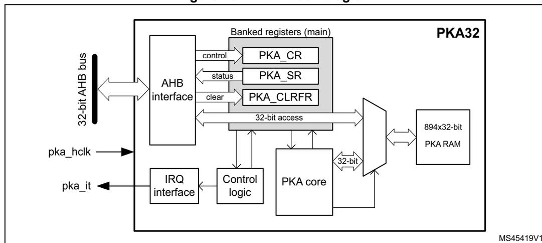
Figure 281 shows the block diagram of the public key accelerator PKA.
Figure 281. PKA block diagram
36.3.2 PKA internal signals
Table 242 lists internal signals available at the IP level, not necessarily available on product bonding pads.
Table 242. Internal input/output signals
| Signal name | Signal type | Description |
|---|---|---|
| pka_hclk | Digital input | AHB bus clock |
| pka_it | Digital output | Public key accelerator IP global interrupt request |
36.3.3 PKA reset and clocks
PKA is clocked on the AHB bus clock. The RAM receives this clock directly, the core is clocked at half the frequency.
When the PKA peripheral reset signal is released PKA RAM is cleared automatically, taking 894 clock cycles. During this time the setting of EN bit in PKA_CR is ignored.
36.3.4 PKA public key acceleration
Overview
Public key accelerator (PKA) is used to accelerate Rivest, Shamir and Adleman (RSA), Diffie-Hellman (DH) as well as ECC over prime field operations. Supported operand sizes is up to 3136 bits for RSA and DH, and up to 640 bits for ECC.
The PKA supports all non-singular elliptic curves defined over prime fields, that can be described with a short Weierstrass equation \( y^2 = x^3 + ax + b \pmod{p} \) . More information is found in Section 36.5.1: Supported elliptic curves .
Note: Binary curves, Edwards curves and Curve25519 are not supported by the PKA.
A memory of 3576 bytes (894 words of 32 bits) called PKA RAM is used for providing initial data to the PKA, and for holding the results after computation is completed. Access is done through the PKA AHB interface.
PKA operating modes
The list of operations the PKA can perform is detailed in Table 243 and Table 244 , respectively, for integer arithmetic functions and prime field ( \( F_p \) ) elliptic curve functions.
Each of these operating modes has an associated code that has to be written to the MODE field in the PKA_CR register.
Table 243. PKA integer arithmetic functions list
| PKA_CR.MODE[5:0] | Performed operation | Reference | |
|---|---|---|---|
| Hex | Binary | ||
| 0x01 | 000001 | Montgomery parameter computation \( R^2 \bmod n \) | Section 36.4.2 |
| 0x0E | 001110 | Modular addition \( (A+B) \bmod n \) | Section 36.4.3 |
| 0x0F | 001111 | Modular subtraction \( (A-B) \bmod n \) | Section 36.4.4 |
| 0x10 | 010000 | Montgomery multiplication \( (AxB) \bmod n \) | Section 36.4.5 |
| 0x00 | 000000 | Modular exponentiation \( A^e \bmod n \) | Section 36.4.6 |
| 0x02 | 000010 | Modular exponentiation \( A^e \bmod n \) (fast mode) | |
| 0x08 | 001000 | Modular inversion \( A^{-1} \bmod n \) | Section 36.4.7 |
| 0x0D | 001101 | Modular reduction \( A \bmod n \) | Section 36.4.8 |
| 0x09 | 001001 | Arithmetic addition \( A+B \) | Section 36.4.9 |
| 0x0A | 001010 | Arithmetic subtraction \( A-B \) | Section 36.4.10 |
| 0x0B | 001011 | Arithmetic multiplication \( AxB \) | Section 36.4.11 |
| 0x0C | 001100 | Arithmetic comparison ( \( A=B, A>B, A<B \) ) | Section 36.4.12 |
| 0x07 | 000111 | RSA CRT exponentiation | Section 36.4.13 |
Table 244. PKA prime field ( \( F_p \) ) elliptic curve functions list
| PKA_CR.MODE[5:0] | Performed operation | Reference | |
|---|---|---|---|
| Hex | Binary | ||
| 0x28 | 101000 | Point on elliptic curve \( F_p \) check | Section 36.4.14 |
| 0x20 | 100000 | ECC scalar multiplication \( kP \) | Section 36.4.15 |
| 0x22 | 100010 | ECC scalar multiplication \( kP \) (fast mode) | |
| 0x24 | 100100 | ECDSA sign | Section 36.4.16 |
| 0x26 | 100110 | ECDSA verification | Section 36.4.17 |
Montgomery space and fast mode operations
For efficiency reason the PKA internally performs modular multiply operations in the Montgomery domain, automatically performing inward and outward transformations.
As Montgomery parameter computation is time consuming the application can decide to use a faster mode of operation, during which the precomputed Montgomery parameter is
supplied before starting the operation. Performance improvement is detailed in Section 36.5.2: Computation times .
The operations using fast mode are modular exponentiation and scalar multiplication.
36.3.5 Typical applications for PKA
Introduction
The PKA can be used to accelerate a number of public key cryptographic functions. In particular:
- • RSA encryption and decryption
- • RSA key finalization
- • CRT-RSA decryption
- • DSA and ECDSA signature generation and verification
- • DH and ECDH key agreement
Specifications of the above functions are given in following publications:
- • FIPS PUB 186-4, Digital Signature Standard (DSS), July 2013 by NIST
- • PKCS #1, RSA Cryptography Standard, v1.5, v2.1 and v2.2. by RSA Laboratories
- • IEEE1363-2000, IEEE Standard Specifications for Public-Key Cryptography, January 2000
- • ANSI X9.62-2005, Public Key Cryptography for the Financial Services Industry, The Elliptic Curve Digital Signature Algorithm (ECDSA), November 2005
The principles of the main functions are described in this section, for a more detailed description refer to the above cited documents.
RSA key pair
For following RSA operations a public key and a private key information are defined as below:
- • Alice transmits her public key \( (n, e) \) to Bob. Numbers \( n \) and \( e \) are very large positive integers.
- • Alice keeps secret her private key \( d \) , also a very large positive integer. Alternatively this private key can also be represented by a quintuple \( (p, q, dp, dq, qInv) \) .
For more information on above representations refer to the RSA specification.
RSA encryption/decryption principle
As recommended by the PKCS#1 specification, Bob, to encrypt message \( M \) using Alice's public key \( (n, e) \) must go through the following steps:
- 1. Compute the encoded message \( EM = ENCODE(M) \) , where \( ENCODE \) is an encoding method.
- 2. Turn \( EM \) into an integer \( m \) , with \( 0 \leq m < n \) and \( (m, n) \) being co-primes.
- 3. Compute ciphertext \( c = m^e \bmod n \) .
- 4. Convert the integer \( c \) into a string ciphertext \( C \) .
Alice, to decrypt ciphertext \( c \) using her private key, follows the steps indicated below:
- 1. Convert the ciphertext \( C \) to an integer ciphertext representative \( c \) .
- 2. Recover plaintext
\(
m = c^d \bmod n = (m^e)^d \bmod n
\)
. If the private key is the quintuple
\(
(p, q, dp, dq, qInv)
\)
, then plaintext
\(
m
\)
is obtained by performing the operations:
- a) \( m_1 = c^{dp} \bmod p \)
- b) \( m_2 = c^{dq} \bmod q \)
- c) \( h = qInv (m_1 - m_2) \bmod p \)
- d) \( m = m_2 + h q \)
- 3. Convert the integer message representative \( m \) to an encoded message EM.
- 4. Recover message \( M = \text{DECODE}(\text{EM}) \) , where \( \text{DECODE} \) is a decoding method.
Above operations can be accelerated by PKA using Modular exponentiation \( A^e \bmod n \) if the private key is \( d \) , or RSA CRT exponentiation if the private key is the quintuple \( (p, q, dp, dq, qInv) \) .
Note: The decoding operation and the conversion operations between message and integers are specified in PKCS#1 standard.
Elliptic curve selection
For following ECC operations curve parameters are defined as below:
- • Curve corresponds to the elliptic curve field agreed among actors (Alice and Bob). Supported curves parameters are summarized in Section 36.5.1: Supported elliptic curves .
- • \( G \) is the chosen elliptic curve base point (also known as generator), with a large prime order \( n \) (i.e. \( n \times G = \text{identity element } O \) ).
ECDSA message signature generation
ECDSA (Elliptic Curve Digital Signature Algorithm) signature generation function principle is the following: Alice, to sign a message \( m \) using her private key integer \( d_A \) , follows the steps below.
- 1. Calculate \( e = \text{HASH}(m) \) , where \( \text{HASH} \) is a cryptographic hash function.
- 2. Let \( z \) be the \( L_n \) leftmost bits of \( e \) , where \( L_n \) is the bit length of the group order \( n \) .
- 3. Select a cryptographically secure random integer \( k \) where \( 0 < k < n \) .
- 4. Calculate the curve point \( (x_1, y_1) = k \times G \) .
- 5. Calculate \( r = x_1 \bmod n \) . If \( r = 0 \) go back to step 3.
- 6. Calculate \( s = k^{-1} (z + r d_A) \bmod n \) . If \( s = 0 \) go back to step 3.
- 7. The signature is the pair \( (r, s) \) .
Steps 4 to 7 are accelerated by PKA using:
- • ECDSA sign or
- • All of the operations below:
- – ECC Fp scalar multiplication \( k \times P \)
- – Modular reduction \( A \bmod n \)
- – Modular inversion \( A^{-1} \bmod n \)
- – Modular addition and Modular and Montgomery multiplication
ECDSA signature verification
ECDSA (elliptic curve digital signature algorithm) signature verification function principle is the following: Bob, to authenticate Alice's signature, must have a copy of her public key curve point \( Q_A \) .
Bob can verify that \( Q_A \) is a valid curve point going through the following steps:
- 1. check that \( Q_A \) is not equal to the identity element O
- 2. check that \( Q_A \) is on the agreed curve
- 3. check that \( n \times Q_A = O \) .
Then Bob follows the procedure detailed below:
- 1. verify that \( r \) and \( s \) are integer in [1, n-1]
- 2. calculate \( e = \text{HASH}(m) \) , where HASH is the agreed cryptographic hash function
- 3. let \( z \) be the \( L_n \) leftmost bits of \( e \)
- 4. calculate \( w = s^{-1} \bmod n \)
- 5. calculate \( u_1 = zw \bmod n \) and \( u_2 = rw \bmod n \)
- 6. calculate the curve point \( (x_1, y_1) = u_1 \times G + u_2 \times Q_A \)
- 7. the signature is valid if \( r = x_1 \pmod{n} \) , it is invalid otherwise.
Steps 4 to 7 are accelerated by PKA using ECDSA verification .
36.3.6 PKA procedure to perform an operation
Enabling/disabling PKA
Setting the EN bit to 1 in PKA_CR register enables the PKA peripheral. When EN = 0, the PKA peripheral is kept under reset, with PKA memory still accessible by the application through the AHB interface.
Clearing EN bit to 0 while a calculation is in progress causes the operation to be aborted. In this case, the content of the PKA memory is not guaranteed.
Data formats
The format of the input data and the results in the PKA RAM are specified, for each operation, in Section 36.4 .
Executing a PKA operation
Each of the supported PKA operation is executed using the following procedure:
- 1. Load initial data into the PKA internal RAM, which is located at address offset 0x400.
- 2. Write in the MODE field of PKA_CR register, specifying the operation which is to be executed and then assert the START bit, also in PKA_CR register.
- 3. Wait until the PROCENDF bit in the PKA_SR register is set to "1", indicating that the computation is complete.
- 4. Read the result data from the PKA internal RAM, then clear PROCENDF bit by setting PROCENDFC bit in PKA_CLRFR.
Note: When PKA is busy (BUSY = 1) any access by the application to PKA RAM is ignored, and the flag RAMERRF is set in PKA_SR.
Using precomputed Montgomery parameters (PKA fast mode)
As explained in Section 36.3.4 , when computing many operations with the same modulus it can be beneficial for the application to compute only once the corresponding Montgomery parameter (see, for example, Section 36.4.5 ). This is known as “fast mode”.
To manage Fast Mode usage the recommended procedure is described below:
- 1. Load in PKA RAM the modulus size and value information. Such information is compiled in Section 36.5.1 .
- 2. Program in PKA_CR register the PKA in Montgomery parameter computation mode (MODE="0x1") then assert the START bit.
- 3. Wait until the PROCENDF bit in the PKA_SR register is set to “1”, then read back from PKA memory the corresponding Montgomery parameter, and then clear PROCENDF bit by setting PROCENDFC bit in PKA_CLRFR.
- 4. Proceed with the required PKA operation, loading on top of regular input data the Montgomery information R 2 mod m. All addresses are indicated in Section 36.4 .
36.3.7 PKA error management
When PKA is used some errors can occur:
- • The access to PKA RAM falls outside the expected range. In this case the Address Error flag (ADDRERRF) is set in the PKA_SR register.
- • An AHB access to the PKA RAM occurred while the PKA core was using it. In this case the RAM Error Flag (RAMERRF) is set in the PKA_SR register, reads to PKA RAM return zero, while writes are ignored.
For each error flag above PKA generates an interrupt if the application sets the corresponding bit in PKA_CR register (see Section 36.6 for details).
ADDRERRF and RAMERRF errors are cleared by setting the corresponding bit in PKA_CLRFR.
The PKA can be re-initialized at any moment by resetting the EN bit in the PKA_CR register.
36.4 PKA operating modes
36.4.1 Introduction
The various operations supported by PKA are described in the following subsections, clarifying the associated format of the input data and of the results, both stored in the PKA RAM.
The following information applies to all PKA operations.
- • PKA core processes 32-bit words
- • Supported operand “Size” are:
- – ROS (RSA operand size): data size is \( (\text{rsa\_size}/32+1) \) words, with rsa_size equal to the chosen modulus length. For example, when computing RSA with an operand size of 1024 bits, ROS is equal to 33 words, or 1056 bits.
- – EOS (ECC operand size): data size is \( (\text{ecc\_size}/32+1) \) words, with ecc_size equal to the chosen prime modulus length. For example, when computing ECC with an operand size of 192 bits, EOS is equal to 7 words, or 224 bits.
Note: Fractional results for above formulas are rounded up to the nearest integer since PKA core processes 32-bit words.
Note: The maximum ROS is 99 words (3136-bit max exponent size), while the maximum EOS is 21 words (640-bit max operand size).
- • The column indicated with Storage in the following tables indicates either the Register PKA_CR, or the address offset within the PKA, located in the PKA RAM area (starting from 0x400). To recover the physical address of an operand the application must add to the indicated offset the base address of the PKA.
- • About writing parameters (“IN” direction)
- – When elements are written as input in the PKA memory, an additional word with all bits equal to zero must be added. As an example, when ECC P256 is used and when loading an input (represented on 256 bits or 8 words), an additional word is expected by the PKA and it has to be filled with zeros.
- – About endianness, for example to prepare the operation ECC Fp scalar multiplication, when application writes \( x_p \) coordinate for an ECC P256 curve (EOS= 9 words) the least significant bit is to be placed in bit 0 at address offset 0x55C; the most significant bit is to be placed in bit 31 of address offset 0x578. Then, as mentioned above, word 0x00000000 should also be written at address offset 0x57C.
- – Unless indicated otherwise all operands in the tables are integers.
- • About PKA outputs (“OUT” direction)
- – Unless specified in the tables PKA does not provide an error output when a wrong parameter is written by the application.
Caution: Validity of all input parameters to the PKA must be checked before issuing any PKA operation. Indeed, the PKA assumes that all input parameters are valid and consistent with each other.
36.4.2 Montgomery parameter computation
This function is used to compute the Montgomery parameter ( \( R^2 \bmod n \) ) used by PKA to convert operands into the Montgomery residue system representation.
Note: This operation can also be used with ECC curves. In this case prime modulus length and EOS size must be used.
Operation instructions for Montgomery parameter computation are summarized in Table 245 .
Table 245. Montgomery parameter computation
| Parameters with direction | Value (Note) | Storage | Size | |
|---|---|---|---|---|
| IN | MODE | 0x01 | PKA_CR | 6 bits |
| Modulus length | (In bits, \( 0 \leq \text{value} < 3136\text{bits} \) ) | RAM@0x404 | 32 bits | |
| Modulus value n | (Odd integer only, \( n < 2^{3136} \) ) | RAM@0xD5C | ||
| OUT | Result: \( R^2 \bmod n \) | - | RAM@0x594 | ROS |
36.4.3 Modular addition
Modular addition operation consists in the computation of \( A + B \bmod n \) . Operation instructions are summarized in Table 246 .
Table 246. Modular addition
| Parameters with direction | Value (Note) | Storage | Size | |
|---|---|---|---|---|
| IN | MODE | 0x0E | PKA_CR | 6 bits |
| Operand length | (In bits, not null) | RAM@0x404 | 32 bits | |
| Operand A | \( (0 \leq A < n) \) | RAM@0x8B4 | ROS | |
| Operand B | \( (0 \leq B < n) \) | RAM@0xA44 | ||
| Modulus value n | \( (n < 2^{3136}) \) | RAM@0xD5C | ||
| OUT | Result: \( A+B \bmod n \) | \( (0 \leq \text{result} < n) \) | RAM@0xBD0 | |
36.4.4 Modular subtraction
Modular subtraction operation consists in the following computations:
- • If \( A \geq B \) result equals \( A - B \bmod n \)
- • If \( A < B \) result equals \( A + n - B \bmod n \)
Operation instructions are summarized in Table 247 .
Table 247. Modular subtraction
| Parameters with direction | Value (Note) | Storage | Size | |
|---|---|---|---|---|
| IN | MODE | 0x0F | PKA_CR | 6 bits |
| Operand length | (In bits, not null) | RAM@0x404 | 32 bits | |
| Operand A | \( (0 \leq A < n) \) | RAM@0x8B4 | ROS | |
| Operand B | \( (0 \leq B < n) \) | RAM@0xA44 | ||
| Modulus value n | \( (n < 2^{3136}) \) | RAM@0xD5C | ||
| OUT | Result: \( A-B \bmod n \) | \( (0 \leq \text{result} < n) \) | RAM@0xBD0 | |
36.4.5 Modular and Montgomery multiplication
To be more efficient when performing a sequence of multiplications the PKA accelerates multiplication which has at least one input in the Montgomery domain. The two main uses of this operation are:
- • Map a value from natural domain to Montgomery domain and vice-versa
- • Perform a modular multiplication \( A \times B \bmod n \)
The method to perform above operations are described below. Note that “x” function is this operation, and A, B, C operands are in the natural domain.
- 1. Inward (or outward) conversion into (or from) Montgomery domain
- a) Let's assume A is an integer in the natural domain
Compute \( r2modn \) using Montgomery parameter computation
Result \( AR = A \times r2modn \bmod n \) is A in the Montgomery domain - b) Let's assume BR is an integer in the Montgomery domain
Result \( B = BR \times 1 \bmod n \) is B in the natural domain
Similarly, above value AR computed in a) can be converted into the natural domain by computing \( A = AR \times 1 \bmod n \)
- a) Let's assume A is an integer in the natural domain
- 2. Simple modular multiplication
\(
A \times B \bmod n
\)
- a) Compute \( r2modn \) using Montgomery parameter computation
- b) Compute \( AR = A \times r2modn \bmod n \) . Output is in the Montgomery domain
- c) Compute \( AB = AR \times B \bmod n \) . Output is in natural domain
- 3. Multiple modular multiplication
\(
A \times B \times C \bmod n
\)
- a) Compute \( r2modn \) using Montgomery parameter computation
- b) Compute \( AR = A \times r2modn \bmod n \) . Output is in the Montgomery domain
- c) Compute \( BR = B \times r2modn \bmod n \) . Output is in the Montgomery domain
- d) Compute \( ABR = AR \times BR \bmod n \) . Output is in the Montgomery domain
- e) Compute \( CR = C \times r2modn \bmod n \) . Output is in the Montgomery domain
- f) Compute \( ABCR = ABR \times CR \bmod n \) . Output is in the Montgomery domain
- g) (optional) Repeat the two steps above if more operands need to be multiplied
- h) Compute \( ABC = ABCR \times 1 \bmod n \) to retrieve the result in natural domain
Operation instructions for Montgomery multiplication are summarized in Table 248 .
Table 248. Montgomery multiplication
| Parameters with direction | Value (Note) | Storage | Size | |
|---|---|---|---|---|
| IN | MODE | 0x10 | PKA_CR | 6 bits |
| Operand length | (In bits, not null) | RAM@0x404 | 32 bits | |
| Operand A | \( (0 \leq A < n) \) | RAM@0x8B4 | ROS | |
| Operand B | \( (0 \leq B < n) \) | RAM@0xA44 | ||
| Modulus value n | (Odd integer only, \( n < 2^{3136} \) ) | RAM@0xD5C | ||
| OUT | Result: \( A \times B \bmod n^{(1)} \) | - | RAM@0xBD0 | |
- 1. Result in Montgomery domain or in natural domain, depending upon the inputs nature (see examples 2 and 3).
36.4.6 Modular exponentiation
Modular exponentiation operation is commonly used to perform a single-step RSA operation. It consists in the computation of \( A^e \bmod n \) .
Operation instructions for modular exponentiation are summarized in Table 249 (normal mode) and in Table 250 (fast mode). Fast mode usage is explained in Section 36.3.6 .
Table 249. Modular exponentiation (normal mode)| Parameters with direction | Value (Note) | Storage | Size | |
|---|---|---|---|---|
| IN | MODE | 0x00 | PKA_CR | 6 bits |
| IN | Exponent length | (in bits, not null) | RAM@0x400 | 32 bits |
| Operand length | (in bits, not null) | RAM@0x404 | ||
| IN/OUT | Operand A (base of exponentiation) | ( \( 0 \leq A < n \) ) | RAM@0xA44 | |
| IN | Exponent e | ( \( 0 \leq e < n \) ) | RAM@0xBD0 | ROS |
| Modulus value n | (Odd integer only, \( n < 2^{3136} \) ) | RAM@0xD5C | ||
| OUT | Result: \( A^e \bmod n \) | ( \( 0 \leq \text{result} < n \) ) | RAM@0x724 | |
| Parameters with direction | Value (Note) | Storage | Size | |
|---|---|---|---|---|
| IN | MODE | 0x02 | PKA_CR | 6 bits |
| IN | Exponent length | (in bits, not null) | RAM@0x400 | 32 bits |
| Operand length | (in bits, not null) | RAM@0x404 | ||
| IN/OUT | Operand A (base of exponentiation) | ( \( 0 \leq A < n \) ) | RAM@0xA44 | |
| IN | Exponent e | ( \( 0 \leq e < n \) ) | RAM@0xBD0 | ROS |
| Modulus value n | (Odd integer only, \( n < 2^{3136} \) ) | RAM@0xD5C | ||
| IN/OUT | Montgomery param R2 mod n | (mandatory) | RAM@0x594 | |
| OUT | Result: \( A^e \bmod n \) | ( \( 0 \leq \text{result} < n \) ) | RAM@0x724 | |
36.4.7 Modular inversion
Modular inversion operation consists in the computation of multiplicative inverse \( A^{-1} \bmod n \) . If the modulus \( n \) is prime, for all values of \( A \) ( \( 1 \leq A < n \) ) modular inversion output is valid. If the modulus \( n \) is not prime, \( A \) has an inverse only if the largest common divisor between \( A \) and \( n \) is 1.
If the operand \( A \) is a divisor of the modulus \( n \) , the result is a multiple of a factor of \( n \) .
Operation instructions for modular inversion are summarized in Table 251 .
Table 251. Modular inversion| Parameters with direction | Value (Note) | Storage | Size | |
|---|---|---|---|---|
| MODE | 0x08 | PKA_CR | 6 bits | |
| IN | Operand length | (In bits, not null) | RAM@0x404 | 32 bits |
| Operand A | ( \( 0 \leq A < n \) ) | RAM@0x8B4 | ||
| Modulus value n | (Odd integer only, \( n < 2^{3136} \) ) | RAM@0xA44 | ||
| OUT | Result: \( A^{-1} \bmod n \) | \( 0 < \text{result} < n \) | RAM@0xBD0 | ROS |
36.4.8 Modular reduction
Modular reduction operation consists in the computation of the remainder of A divided by n. Operation instructions are summarized in Table 252 .
Table 252. Modular reduction
| Parameters with direction | Value (Note) | Storage | Size | |
|---|---|---|---|---|
| IN | MODE | 0x0D | PKA_CR | 6 bits |
| Operand length | (In bits, not null) | RAM@0x400 | 32 bits | |
| Modulus length | (In bits, \( 8 < \text{value} < 3136 \) ) | RAM@0x404 | ||
| Operand A | \( (0 \leq A < 2n < 2^{3136}) \) | RAM@0x8B4 | ROS | |
| Modulus value n | (Odd integer only, \( n < 2^{3136} \) ) | RAM@0xA44 | ||
| OUT | Result A mod n | \( (0 < \text{result} < n) \) | RAM@0xBD0 | |
36.4.9 Arithmetic addition
Arithmetic addition operation consists in the computation of \( A + B \) . Operation instructions are summarized in Table 253 .
Table 253. Arithmetic addition
| Parameters with direction | Value (Note) | Storage | Size | |
|---|---|---|---|---|
| IN | MODE | 0x09 | PKA_CR | 6 bits |
| Operand length M | (In bits, not null) | RAM@0x404 | 32 bits | |
| Operand A | \( (0 \leq A < 2^M) \) | RAM@0x8B4 | ROS | |
| Operand B | \( (0 \leq B < 2^M) \) | RAM@0xA44 | ||
| OUT | Result: A+B | \( (0 \leq \text{result} < 2^{M+1}) \) | RAM@0xBD0 | ROS + 1 |
36.4.10 Arithmetic subtraction
Arithmetic subtraction operation consists in the following computations:
- • If \( A \geq B \) result equals \( A - B \)
- • If \( A < B \) and \( M/32 \) residue is \( > 0 \) result equals \( A + 2^{\text{int}(M/32)*32+1} - B \)
- • If \( A < B \) and \( M/32 \) residue is 0 result equals \( A + 2^{\text{int}(M/32)*32} - B \)
Operation instructions are summarized in Table 254 .
Table 254. Arithmetic subtraction
| Parameters with direction | Value (Note) | Storage | Size | |
|---|---|---|---|---|
| IN | MODE | 0x0A | PKA_CR | 6 bits |
| Operand length M | (In bits, not null) | RAM@0x404 | 32 bits | |
| Operand A | \( (0 \leq A < 2^M) \) | RAM@0x8B4 | ROS | |
| Operand B | \( (0 \leq B < 2^M) \) | RAM@0xA44 | ||
| OUT | Result: A-B | \( (0 \leq \text{result} < 2^M) \) | RAM@0xBD0 | |
36.4.11 Arithmetic multiplication
Arithmetic multiplication operation consists in the computation of \( A \times B \) . Operation instructions are summarized in Table 255 .
Table 255. Arithmetic multiplication
| Parameters with direction | Value (Note) | Storage | Size | |
|---|---|---|---|---|
| IN | MODE | 0x0B | PKA_CR | 6 bits |
| Operand length M | (In bits, not null) | RAM@0x404 | 32 bits | |
| Operand A | \( (0 \leq A < 2^M) \) | RAM@0x8B4 | ROS | |
| Operand B | \( (0 \leq B < 2^M) \) | RAM@0xA44 | ||
| OUT | Result: \( A \times B \) | \( (0 \leq \text{result} < 2^M) \) | RAM@0xBD0 | 2xROS |
36.4.12 Arithmetic comparison
Arithmetic comparison operation consists in the following computation:
- • If \( A=B \) then result=0x0
- • If \( A>B \) then result=0x1
- • If \( A<B \) then result=0x2
Operation instructions for arithmetic comparison are summarized in Table 256 .
Table 256. Arithmetic comparison
| Parameters with direction | Value (Note) | Storage | Size | |
|---|---|---|---|---|
| IN | MODE | 0x0C | PKA_CR | 6 bits |
| Operand length M | (In bits, not null) | RAM@0x404 | 32 bits | |
| Operand A | \( (0 \leq A < 2^M) \) | RAM@0x8B4 | ROS | |
| Operand B | \( (0 \leq B < 2^M) \) | RAM@0xA44 | ||
| OUT | Result \( A=B \) or \( A>B \) or \( A<B \) | 0x0, 0x1 or 0x2 | RAM@0xBD0 | 32 bits |
36.4.13 RSA CRT exponentiation
For efficiency many popular crypto libraries like OpenSSL RSA use the following optimization for decryption and signing based on the Chinese remainder theorem (CRT):
- • \( p \) and \( q \) are precomputed primes, stored as part of the private key
- • \( d_p = d \bmod (p - 1) \)
- • \( d_q = d \bmod (q - 1) \) and
- • \( q_{\text{inv}} = q^{-1} \bmod p \)
These values allow the recipient to compute the exponentiation \( m = A^d \pmod{pq} \) more efficiently as follows:
- • \( m_1 = A^{d_P} \pmod{p} \)
- • \( m_2 = A^{d_Q} \pmod{q} \)
- • \( h = q_{\text{inv}} (m_1 - m_2) \pmod{p} \) , with \( m_1 > m_2 \)
- • \( m = m_2 + hq \)
Operation instructions for computing CRT exponentiation \( A^d \pmod{pq} \) are summarized in Table 257 .
Table 257. CRT exponentiation
| Parameters with direction | Value (Note) | Storage | Size | |
|---|---|---|---|---|
| IN | MODE | 0x07 | PKA_CR | 6 bits |
| IN | Operand length | (in bits, not null) | RAM@0x404 | 32 bits |
| IN | Operand \( d_P \) | \( (0 \leq d_P < 2^{M/2}) \) | RAM@0x65C | ROS/2 |
| Operand \( d_Q \) | \( (0 \leq d_Q < 2^{M/2}) \) | RAM@0xBD0 | ||
| Operand \( q_{\text{inv}} \) | \( (0 \leq q_{\text{inv}} < 2^{M/2}) \) | RAM@0x7EC | ||
| Prime \( p^{(1)} \) | \( (0 \leq p < 2^{M/2}) \) | RAM@0x97C | ||
| Prime \( q^{(1)} \) | \( (0 \leq q < 2^{M/2}) \) | RAM@0xD5C | ||
| IN | Operand A | \( (0 \leq A < 2^{M/2}) \) | RAM@0xEEC | ROS |
| OUT | Result: \( A^d \pmod{pq} \) | \( (0 \leq \text{result} < pq) \) | RAM@0x724 | |
1. Must be different from 2.
36.4.14 Point on elliptic curve Fp check
This operation consists in checking whether a given point \( P(x, y) \) satisfies or not the curves over prime fields equation \( y^2 = (x^3 + ax + b) \pmod{p} \) , where \( a \) and \( b \) are elements of the curve.
Operation instructions for point on elliptic curve Fp check are summarized in Table 258 .
Table 258. Point on elliptic curve Fp check| Parameters with direction | Value (Note) | Storage | Size | |
|---|---|---|---|---|
| IN | MODE | 0x28 | PKA_CR | 6 bits |
| Modulus length | (In bits, not null, \( 8 < \text{value} < 640 \) ) | RAM@0x404 | 32 bits | |
| Curve coefficient a sign | 0x0: positive 0x1: negative | RAM@0x408 | ||
| Curve coefficient | a | | (Absolute value, \( |a| < p \) ) | RAM@0x40C | EOS | |
| Curve coefficient b | ( \( |b| < p \) ) | RAM@0x7FC | ||
| Curve modulus value p | (Odd integer prime, \( 0 < p < 2^{640} \) ) | RAM@0x460 | ||
| Point P coordinate x | ( \( x < p \) ) | RAM@0x55C | ||
| Point P coordinate y | ( \( y < p \) ) | RAM@0x5B0 | ||
| OUT | Result: P on curve | 0x0: point on curve Not 0x0: point not on curve | RAM@0x400 | 32 bits |
36.4.15 ECC Fp scalar multiplication
This operation consists in the computation of a \( k \times P (x_P, y_P) \) , where P is a point on a curve over prime fields and “x” is the elliptic curve scalar point multiplication. Result of the computation is a point that belongs to the same curve or a point at infinity.
Operation instructions for ECC Fp scalar multiplication are summarized in Table 259 (normal mode) and Table 260 (fast mode). Fast mode usage is explained in Section 36.3.6 .
Table 259. ECC Fp scalar multiplication| Parameters with direction | Value (Note) | Storage | Size | |
|---|---|---|---|---|
| IN | MODE | 0x20 | PKA_CR | 6 bits |
| IN | Scalar multiplier k length | (In bits, not null, \( 8 < \text{value} < 640 \) ) | RAM@0x400 | 32 bits |
| Modulus length | (In bits, not null, \( 8 < \text{value} < 640 \) ) | RAM@0x404 | ||
| Curve coefficient a sign | 0x0: positive 0x1: negative | RAM@0x408 | EOS | |
| Curve coefficient | a | | (Absolute value, \( |a| < p \) ) | RAM@0x40C | ||
| Curve modulus value p | (Odd integer prime, \( 0 < p < 2^{640} \) ) | RAM@0x460 | ||
| Scalar multiplier k | ( \( 0 \le k < 2^{640} \) ) | RAM@0x508 | ||
| Point P coordinate x P | ( \( x < p \) ) | RAM@0x55C | ||
| Point P coordinate y P | ( \( y < p \) ) | RAM@0x5B0 | ||
| OUT | Result: \( k \times P \) coordinate x | (result \( < p \) ) | RAM@0x55C | 32 bits |
| Result: \( k \times P \) coordinate y | (result \( < p \) ) | RAM@0x5B0 | ||
Table 260. ECC Fp scalar multiplication (Fast Mode)
| Parameters with direction | Value (Note) | Storage | Size | |
|---|---|---|---|---|
| IN | MODE | 0x22 | PKA_CR | 6 bits |
| IN | Scalar multiplier k length | (In bits, not null, \( 8 < \text{value} < 640 \) ) | RAM@0x400 | 32 bits |
| Modulus length | (In bits, not null, \( 8 < \text{value} < 640 \) ) | RAM@0x404 | ||
| Curve coefficient a sign | 0x0: positive 0x1: negative | RAM@0x408 | ||
| IN | Curve coefficient |a| | (Absolute value, \( |a| < p \) ) | RAM@0x40C | EOS |
| Curve modulus value \( p \) | (Odd integer prime, \( 0 < p < 2^{640} \) ) | RAM@0x460 | ||
| Scalar multiplier k | ( \( 0 \leq k < 2^{640} \) ) | RAM@0x508 | ||
| Point P coordinate \( x_P \) | ( \( x < p \) ) | RAM@0x55C | ||
| Point P coordinate \( y_P \) | ( \( y < p \) ) | RAM@0x5B0 | ||
| IN | Montgomery parameter \( R^2 \bmod p \) | (mandatory) | RAM@0x4B4 | |
| OUT | Result: k x P coordinate x | (result \( < p \) ) | RAM@0x55C | |
| Result: k x P coordinate y | (result \( < p \) ) | RAM@0x5B0 | ||
When performing this operation following special cases should be noted:
- • For \( k = 0 \) , this function returns a point at infinity, that is \( (0, 0) \) if curve parameter \( b \) is nonzero and \( (0, 1) \) otherwise. For \( k \) different from 0 it might happen that a point at infinity is returned. When the application detects this behavior a new computation should be carried out.
- • For \( k < 0 \) (i.e. a negative scalar multiplication is required) multiplier absolute value \( k = |-k| \) should be provided to the PKA. After the computation completion, the formula \( -P = (x, -y) \) can be used to compute the y coordinate of the effective final result (the x coordinate remains the same).
36.4.16 ECDSA sign
ECDSA signing operation (outlined in Section 36.3.5 ) is summarized in Table 261 (input parameters) and in Table 262 (output parameters).
The application should check if the output error is equal to zero, if it is different from zero a new \( k \) should be generated and the ECDSA sign operation should be repeated.
Table 261. ECDSA sign - Inputs
| Parameters with direction | Value (Note) | Storage | Size | |
|---|---|---|---|---|
| IN | MODE | 0x24 | PKA_CR | 6 bits |
| Curve prime order n length | (in bits, not null) | RAM@0x400 | 32 bits | |
| Curve modulus p length | (in bits, \( 8 < \text{value} < 640 \) ) | RAM@0x404 | ||
| Curve coefficient a sign | 0x0: positive 0x1: negative | RAM@0x408 | ||
| Curve coefficient |a| | (Absolute value, \( |a| < p \) ) | RAM@0x40C | EOS | |
| Curve modulus value p | (Odd integer prime, \( 0 < p < 2^{640} \) ) | RAM@0x460 | ||
| Integer k (1) | ( \( 0 \leq k < 2^{640} \) ) | RAM@0x508 | ||
| Curve base point G coordinate x | ( \( x < p \) ) | RAM@0x55C | ||
| Curve base point G coordinate y | ( \( y < p \) ) | RAM@0x5B0 | ||
| Hash of message z | ( \( z < 2M \) ) | RAM@0xDE8 | ||
| Private key d | (positive integer) | RAM@0xE3C | ||
| Curve prime order n | (integer prime) | RAM@0xE94 | ||
- 1. This integer is usually a cryptographically secure random number, but in some cases k could be deterministically generated.
Table 262. ECDSA sign - Outputs
| Parameters with direction | Value (Note) | Storage | Size | |
|---|---|---|---|---|
| OUT | Signature part r | ( \( 0 < r < n \) ) | RAM@0x700 | EOS |
| Signature part s | ( \( 0 < s < n \) ) | RAM@0x754 | ||
| ERROR | Result of signature | – 0x0: no error – 0x1: signature part r is equal to 0 – 0x2: signature part s is equal to 0 | RAM@0xEE8 | 32 bits |
Note: If error output is different from zero the content of the PKA memory should be cleared to avoid leaking information about the private key.
Extended ECDSA support
PKA also supports Extended ECDSA signature, for which the inputs and the outputs have the same ECDSA signature (Table 261 and Table 262, respectively), with the addition of the coordinates of the point kG. This extra output is defined in Table 263.
Table 263. Extended ECDSA sign (extra outputs)| Parameters with direction | Value (Note) | Storage | Size | |
|---|---|---|---|---|
| OUT | Curve point kG coordinate \( x_1 \) | \( (0 \leq x_1 < p) \) | RAM@0x103C | EOS |
| Curve point kG coordinate \( y_1 \) | \( (0 \leq y_1 < p) \) | RAM@0x1090 | ||
36.4.17 ECDSA verification
ECDSA verification operation (outlined in Section 36.3.5 ) is summarized in Table 264 (input parameters) and Table 265 (output parameters).
The application should check if the output error is equal to zero, if it is different from zero, the signature is not verified.
Table 264. ECDSA verification (inputs)| Parameters with direction | Value (Note) | Storage | Size | |
|---|---|---|---|---|
| IN | MODE | 0x26 | PKA_CR | 6 bits |
| Curve prime order \( n \) length | (In bits, not null) | RAM@0x404 | 32 bits | |
| Curve modulus \( p \) length | (In bits, not null, \( 8 < \text{value} < 640 \) ) | RAM@0x4B4 | ||
| Curve coefficient \( a \) sign | 0x0: positive 0x1: negative | RAM@0x45C | ||
| Curve coefficient \( |a| \) | (Absolute value, \( |a| < p \) ) | RAM@0x460 | EOS | |
| Curve modulus value \( p \) | (Odd integer prime, \( 0 < p < 2^{640} \) ) | RAM@0x4B8 | ||
| Curve base point G coordinate \( x \) | \( (x < p) \) | RAM@0x5E8 | ||
| Curve base point G coordinate \( y \) | \( (y < p) \) | RAM@0x63C | ||
| Public-key curve point Q coordinate \( x_Q \) | \( (x_Q < p) \) | RAM@0xF40 | ||
| Public-key curve point Q coordinate \( y_Q \) | \( (y_Q < p) \) | RAM@0xF94 | ||
| Signature part \( r \) | \( (0 < r < n) \) | RAM@0x1098 | ||
| Signature part \( s \) | \( (0 < s < n) \) | RAM@0xA44 | ||
| Hash of message \( z \) | \( (z < 2^M) \) | RAM@0xFE8 | ||
| Curve prime order \( n \) | (integer prime) | RAM@0xD5C | ||
| Parameters with direction | Value (Note) | Storage | Size | |
|---|---|---|---|---|
| OUT | Result: ECDSA verify | 0x0: valid signature Not 0x0: invalid signature | RAM@0x5B0 | 32 bits |
36.5 Example of configurations and processing times
36.5.1 Supported elliptic curves
The PKA supports all non-singular elliptic curves defined over prime fields. Those curves can be described with a short Weierstrass equation \( y^2 = x^3 + ax + b \pmod p \) .
Note: Binary curves, Edwards curves and Curve25519 are not supported by the PKA. The maximum supported operand size for ECC operations is 640 bits.
When publishing the ECC domain parameters of those elliptic curves, standard bodies define the following parameters:
- • the prime integer \( p \) , used as the modulus for all point arithmetic in the finite field \( GF(p) \)
- • the (usually prime) integer \( n \) , the order of the group generated by \( G \) , defined below
- • the base point of the curve \( G \) , defined by its coordinates \( (G_x, G_y) \)
- • the integers \( a \) and \( b \) , coefficients of the short Weierstrass equation.
For the last bullet, when standard bodies define \( a \) as negative, PKA supports two representations:
- 1.
a defined as
\(
p-|a|
\)
in the finite field
\(
GF(p)
\)
, for example
p-3
:
Curve coefficient \( p = \text{0xFFFFFFFFE FFFFFFFF FFFFFFFF FFFFFFFF FFFFFFFF} \)
\( 00000000 \text{ FFFFFFFF FFFFFFFF} \)
Curve coefficient \( a \) sign= \( 0x0 \) (positive)
Curve coefficient \( a = \text{0xFFFFFFFFE FFFFFFFF FFFFFFFF FFFFFFFF FFFFFFFF} \)
\( 00000000 \text{ FFFFFFFF FFFFFFFC} \) - 2.
a defined as negative
, for example
-3
:
Curve coefficient \( p = \text{0xFFFFFFFFE FFFFFFFF FFFFFFFF FFFFFFFF FFFFFFFF} \)
\( 00000000 \text{ FFFFFFFF FFFFFFFF} \)
Curve coefficient \( a \) sign= \( 0x1 \) (negative)
Curve coefficient \( a = \text{0x00000000 00000000 00000000 00000000 00000000 00000000} \)
\( 00000000 \text{ 00000003} \)
Table 266 summarizes the family of curves supported by PKA for ECC operations.
Table 266. Family of supported curves for ECC operations
| Curve name | Standard | Reference |
|---|---|---|
| P-192 | NIST | Digital Signature Standard (DSS), NIST FIPS 186-4 |
| P-224 | ||
| P-256 | ||
| P-384 | ||
| P-521 |
Table 266. Family of supported curves for ECC operations (continued)
| Curve name | Standard | Reference | |
|---|---|---|---|
| brainpoolP224r1, brainpoolP224t1 | IETF | –
Brainpool Elliptic Curves
, IETF RFC 5639 – Brainpool Elliptic Curves for the Internet Key Exchange (IKE) Group Description Registry , IETF RFC 6932 | https://tools.ietf.org |
| brainpoolP256r1, brainpoolP256t1 | |||
| brainpoolP320r1, brainpoolP320t1 | |||
| brainpoolP384r1, brainpoolP384t1 | |||
| brainpoolP512r1, brainpoolP512t1 | |||
| secp192k1, secp192r1 | SEC | Standards for Efficient Cryptography SEC 2 curves | https://www.secg.org |
| secp224k1, secp224r1 | |||
| secp256k1, secp256r1 | |||
| secp384r1 | |||
| secp521r1 | |||
| Recommended curve parameters for public key cryptographic algorithm SM2 | OSCCA | –
Public key cryptographic algorithm SM2 based on elliptic curves
, Organization of State Commercial Administration of China OSCCA SM2, December 2010 – Digital signatures - Part 3 Discrete logarithm based mechanisms , ISO/IEC 14888-3, November 2018 | |
36.5.2 Computation times
The following tables summarize the PKA computation times, expressed in clock cycles.
Table 267. Modular exponentiation computation times
| Exponent length (in bits) | Mode | Modulus length (in bits) | ||
|---|---|---|---|---|
| 1024 | 2048 | 3072 | ||
| 3 | Normal | 304000 | 814000 | 1728000 |
| Fast | 46000 | 164000 | 356000 | |
| 17 | Normal | 326000 | 896000 | 1910000 |
| Fast | 68000 | 246000 | 534000 | |
| \( 2^{16} + 1 \) | Normal | 416000 | 1222000 | 2616000 |
| Fast | 158000 | 572000 | 1244000 | |
| 1024 | Normal | 11664000 | - | - |
| Fast | 11280000 | - | - | |
| CRT (1) | 3546000 | - | - | |
| 2048 | Normal | - | 83834000 | - |
| Fast | - | 82046000 | - | |
| CRT (1) | - | 23468000 | - | |
| 3072 | Normal | - | - | 274954000 |
| Fast | - | - | 273522000 | |
| CRT (1) | - | - | 73378000 | |
1. CRT stands for chinese remainder theorem optimization (MODE bitfield = 0x07).
Table 268. ECC scalar multiplication computation times (1)
| Mode | Modulus length (in bits) | ||||||
|---|---|---|---|---|---|---|---|
| 160 | 192 | 256 | 320 | 384 | 512 | 521 | |
| Normal | 1634000 | 2500000 | 4924000 | 8508000 | 13642000 | 28890000 | 33160000 |
| Fast | 1630000 | 2494000 | 4916000 | 8494000 | 13614000 | 28842000 | 33158000 |
1. These times depend on the number of "1"s included in the scalar parameter.
Table 269. ECDSA signature average computation times (1) (2)
| Modulus length (in bits) | ||||||
|---|---|---|---|---|---|---|
| 160 | 192 | 256 | 320 | 384 | 512 | 521 |
| 1760000 | 2664000 | 5249000 | 9016000 | 14596000 | 30618000 | 35540000 |
- 1. These values are average execution times of random moduli of given length, as they depend upon the length and the value of the modulus.
- 2. The execution time for the moduli that define the finite field of NIST elliptic curves is shorter than that needed for the moduli used for Brainpool elliptic curves or for random moduli of the same size.
Table 270. ECDSA verification average computation times
| Modulus length (in bits) | ||||||
|---|---|---|---|---|---|---|
| 160 | 192 | 256 | 320 | 384 | 512 | 521 |
| 3500000 | 5350000 | 10498000 | 18126000 | 29118000 | 61346000 | 71588000 |
Table 271. Point on elliptic curve Fp check average computation times
| Modulus length (in bits) | |||||
|---|---|---|---|---|---|
| 160 | 192 | 256 | 320 | 384 | 512 |
| 10800 | 14200 | 20400 | 31000 | 49600 | 82400 |
| Modulus length (in bits) | |||||||||
|---|---|---|---|---|---|---|---|---|---|
| 160 | 192 | 256 | 320 | 384 | 512 | 521 | 1024 | 2048 | 3072 |
| 4518 | 7846 | 11848 | 14902 | 21682 | 35012 | 64000 | 119536 | 466146 | 1104642 |
- 1. The computation times depend upon the length and the value of the modulus, hence these values are average execution times of random moduli of given length.
36.6 PKA interrupts
There are three individual maskable interrupt sources generated by the public key accelerator, signaling the following events:
- 1. access to unmapped address (ADDRERRF), see Section 36.3.7
- 2. PKA RAM access while PKA operation is in progress (RAMERRF), see Section 36.3.7
- 3. PKA end of operation (PROCENDF)
The three interrupt sources are connected to the same global interrupt request signal pka_it.
The user can enable or disable above interrupt sources individually by changing the mask bits in the PKA control register (PKA_CR) . Setting the appropriate mask bit to 1 enables the interrupt. The status of the individual interrupt events can be read from the PKA status register (PKA_SR), and it is cleared in PKA_CLRFR register.
Table 273 gives a summary of the available features.
Table 273. PKA interrupt requests
| Interrupt acronym | Interrupt event | Event flag | Enable control bit | Interrupt clear method |
|---|---|---|---|---|
| PKA | Access to unmapped address error | ADDRERRF | ADDRERRIE | Set ADDRERRFC bit |
| PKA RAM access error | RAMERRF | RAMERRIE | Set RAMERRFC bit | |
| PKA end of operation | PROCENDF | PROCENDIE | Set PROCENDFC bit |
36.7 PKA registers
36.7.1 PKA control register (PKA_CR)
Address offset: 0x00
Reset value: 0x0000 0000
| 31 | 30 | 29 | 28 | 27 | 26 | 25 | 24 | 23 | 22 | 21 | 20 | 19 | 18 | 17 | 16 |
|---|---|---|---|---|---|---|---|---|---|---|---|---|---|---|---|
| Res. | Res. | Res. | Res. | Res. | Res. | Res. | Res. | Res. | Res. | Res. | ADDR ERRIE | RAM ERRIE | Res. | PROC ENDIE | Res. |
| 15 | 14 | 13 | 12 | 11 | 10 | 9 | 8 | 7 | 6 | 5 | 4 | 3 | 2 | 1 | 0 |
| Res. | Res. | MODE[5:0] | Res. | Res. | Res. | Res. | Res. | Res. | START | EN | |||||
| rw | rw | rw | rw | rw | rw | rw | rw | ||||||||
Bits 31:21 Reserved, must be kept at reset value.
Bit 20 ADDRERRIE : Address error interrupt enable
0: No interrupt is generated when ADDRERRF flag is set in PKA_SR.
1: An interrupt is generated when ADDRERRF flag is set in PKA_SR.
Bit 19 RAMERRIE : RAM error interrupt enable
0: No interrupt is generated when RAMERRF flag is set in PKA_SR.
1: An interrupt is generated when RAMERRF flag is set in PKA_SR.
Bit 18 Reserved, must be kept at reset value.
Bit 17 PROCENDIE : End of operation interrupt enable
0: No interrupt is generated when PROCENDF flag is set in PKA_SR.
1: An interrupt is generated when PROCENDF flag is set in PKA_SR.
Bits 16:14 Reserved, must be kept at reset value.
Bits 13:8 MODE[5:0] : PKA operation code
000000: Montgomery parameter computation then modular exponentiation
000001: Montgomery parameter computation only
000010: Modular exponentiation only (Montgomery parameter must be loaded first)
100000: Montgomery parameter computation then ECC scalar multiplication
100010: ECC scalar multiplication only (Montgomery parameter must be loaded first)
100100: ECDSA sign
100110: ECDSA verification
101000: Point on elliptic curve Fp check
000111: RSA CRT exponentiation
001000: Modular inversion
001001: Arithmetic addition
001010: Arithmetic subtraction
001011: Arithmetic multiplication
001100: Arithmetic comparison
001101: Modular reduction
001110: Modular addition
001111: Modular subtraction
010000: Montgomery multiplication
Others: Reserved
Bits 7:2 Reserved, must be kept at reset value.
Bit 1 START : start the operation
Writing 1 to this bit starts the operation which is selected by MODE[5:0], using the operands and data already written to the PKA RAM. This bit is always read as 0.
Note: START is ignored if PKA is busy.
Bit 0 EN : PKA enable.
0: Disable PKA
1: Enable PKA
Note: When EN=0 PKA RAM can still be accessed by the application.
36.7.2 PKA status register (PKA_SR)
Address offset: 0x04
Reset value: 0x0000 0000
| 31 | 30 | 29 | 28 | 27 | 26 | 25 | 24 | 23 | 22 | 21 | 20 | 19 | 18 | 17 | 16 |
|---|---|---|---|---|---|---|---|---|---|---|---|---|---|---|---|
| Res. | Res. | Res. | Res. | Res. | Res. | Res. | Res. | Res. | Res. | Res. | ADDR ERRF | RAM ERRF | Res. | PROC ENDF | BUSY |
| r | r | r | r | ||||||||||||
| 15 | 14 | 13 | 12 | 11 | 10 | 9 | 8 | 7 | 6 | 5 | 4 | 3 | 2 | 1 | 0 |
| Res. | Res. | Res. | Res. | Res. | Res. | Res. | Res. | Res. | Res. | Res. | Res. | Res. | Res. | Res. | Res. |
Bits 31:21 Reserved, must be kept at reset value.
Bit 20 ADDRERRF : Address error flag
0: No Address error
1: Address access is out of range (unmapped address)
This bit is cleared using ADDRERRFC bit in PKA_CLRFR.
Bit 19 RAMERRF : PKA RAM error flag
0: No PKA RAM access error
1: An AHB access to the PKA RAM occurred while the PKA core was computing and using its internal RAM (AHB PKA_RAM access are not allowed while PKA operation is in progress).
This bit is cleared using RAMERRFC bit in PKA_CLRFR.
Bit 18 Reserved, must be kept at reset value.
Bit 17 PROCENDF : PKA End of Operation flag
0: Operation in progress
1: PKA operation is completed. This flag is set when the BUSY bit is deasserted.
Bit 16 BUSY : PKA operation is in progress
This bit is set to 1 whenever START bit in the PKA_CR is set. It is automatically cleared when the computation is complete, meaning that PKA RAM can be safely accessed and a new operation can be started.
0: No operation is in progress (default)
1: An operation is in progress
If PKA is started with a wrong opcode the peripheral is busy for a couple of cycles, then it aborts automatically the operation and go back to ready (BUSY bit is set to 0).
Bits 15:0 Reserved, must be kept at reset value.
36.7.3 PKA clear flag register (PKA_CLRFR)
Address offset: 0x08
Reset value: 0x0000 0000
| 31 | 30 | 29 | 28 | 27 | 26 | 25 | 24 | 23 | 22 | 21 | 20 | 19 | 18 | 17 | 16 |
|---|---|---|---|---|---|---|---|---|---|---|---|---|---|---|---|
| Res. | Res. | Res. | Res. | Res. | Res. | Res. | Res. | Res. | Res. | Res. | ADDR ERRFC | RAM ERRFC | Res. | PROC ENDFC | Res. |
| w | w | w | |||||||||||||
| 15 | 14 | 13 | 12 | 11 | 10 | 9 | 8 | 7 | 6 | 5 | 4 | 3 | 2 | 1 | 0 |
| Res. | Res. | Res. | Res. | Res. | Res. | Res. | Res. | Res. | Res. | Res. | Res. | Res. | Res. | Res. | Res. |
Bits 31:21 Reserved, must be kept at reset value.
Bit 20 ADDRERRFC : Clear Address error flag
0: No action
1: Clear the ADDRERRF flag in PKA_SR
Bit 19 RAMERRFC : Clear PKA RAM error flag
0: No action
1: Clear the RAMERRF flag in PKA_SR
Bit 18 Reserved, must be kept at reset value.
Bit 17 PROCENDFC : Clear PKA End of Operation flag
0: No action
1: Clear the PROCENDF flag in PKA_SR
Bits 16:0 Reserved, must be kept at reset value.
Note: Reading PKA_CLRFR returns all 0s.
36.7.4 PKA RAM
The PKA RAM is mapped at the offset address of 0x0400 compared to the PKA base address. Only 32-bit word single accesses are supported, through PKA.AHB interface.
RAM size is 3576 bytes (max word offset: 0x11F4).
36.7.5 PKA register map
Table 274. PKA register map and reset values
| Offset | Register name | 31 | 30 | 29 | 28 | 27 | 26 | 25 | 24 | 23 | 22 | 21 | 20 | 19 | 18 | 17 | 16 | 15 | 14 | 13 | 12 | 11 | 10 | 9 | 8 | 7 | 6 | 5 | 4 | 3 | 2 | 1 | 0 |
|---|---|---|---|---|---|---|---|---|---|---|---|---|---|---|---|---|---|---|---|---|---|---|---|---|---|---|---|---|---|---|---|---|---|
| 0x000 | PKA_CR | Res | Res | Res | Res | Res | Res | Res | Res | Res | Res | Res | ADDRERRIE | RAMERRIE | Res | PROCENDIE | Res | Res | Res | MODE[5:0] | Res | Res | Res | Res | Res | Res | START | EN | |||||
| Reset value | 0 | 0 | 0 | 0 | 0 | 0 | 0 | 0 | 0 | 0 | 0 | ||||||||||||||||||||||
| 0x004 | PKA_SR | Res | Res | Res | Res | Res | Res | Res | Res | Res | Res | Res | ADDRERRF | RAMERRF | Res | PROCENDF | BUSY | Res | Res | Res | Res | Res | Res | Res | Res | Res | Res | Res | Res | Res | Res | Res | Res |
| Reset value | 0 | 0 | 0 | 0 | |||||||||||||||||||||||||||||
| 0x008 | PKA_CLRFR | Res | Res | Res | Res | Res | Res | Res | Res | Res | Res | Res | ADDRERRFC | RAMERRFC | Res | PROCENDFC | Res | Res | Res | Res | Res | Res | Res | Res | Res | Res | Res | Res | Res | Res | Res | Res | Res |
| Reset value | 0 | 0 | 0 | ||||||||||||||||||||||||||||||
Refer to Section 2.2 on page 93 for the register boundary addresses.