35. JPEG codec (JPEG)
35.1 Introduction
The hardware 8-bit JPEG codec encodes uncompressed image data stream or decodes JPEG-compressed image data stream. It also fully manages JPEG headers.
35.2 JPEG codec main features
- • High-speed fully-synchronous operation
- • Configurable as encoder or decoder
- • Single-clock-per-pixel encode/decode
- • RGB, YCbCr, YCMK and BW (grayscale) image color space support
- • 8-bit depth per image component at encode/decode
- • JPEG header generator/parser with enable/disable
- • Four programmable quantization tables
- • Single-clock Huffman coding and decoding
- • Fully-programmable Huffman tables (two AC and two DC)
- • Fully-programmable minimum coded unit (MCU)
- • Concurrent input and output data stream interfaces
35.3 JPEG codec block functional description
35.3.1 General description
The block diagram of the JPEG codec is shown in Figure 292 .
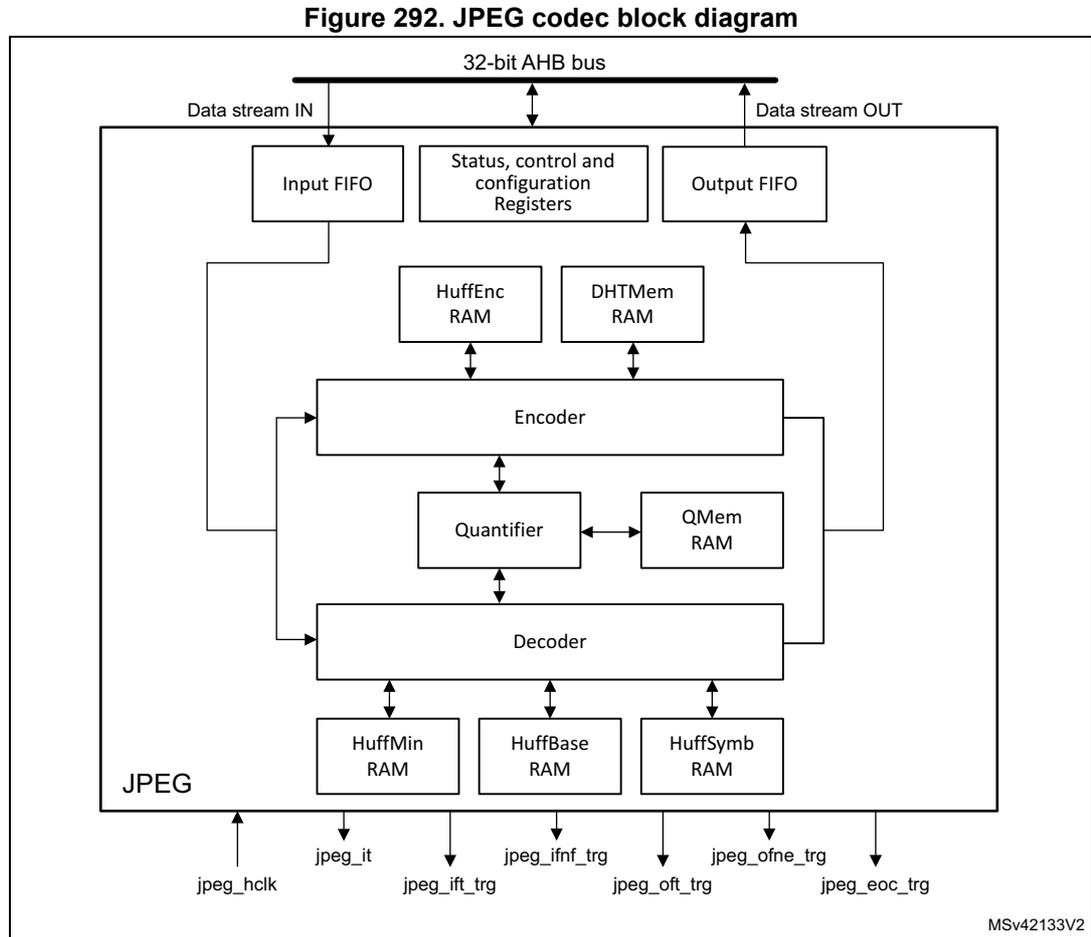
Figure 292. JPEG codec block diagram
The diagram illustrates the internal architecture of the JPEG codec. At the top, a horizontal line represents the 32-bit AHB bus . Below it, three main components are connected to this bus: Data stream IN (leading to an Input FIFO ), Status, control and configuration Registers , and Data stream OUT (receiving data from an Output FIFO ). The Input FIFO feeds into an Encoder , which in turn connects to a Quantifier . The Quantifier is bidirectionally connected to a QMem RAM and also feeds into a Decoder . The Decoder connects to three RAMs: HuffMin RAM , HuffBase RAM , and HuffSymb RAM . Above the Encoder , there are two more RAMs: HuffEnc RAM and DHTMem RAM , both connected to the encoder. The entire internal structure is labeled JPEG . At the bottom, several signals are shown: jpeg_hclk (input), jpeg_it (output), jpeg_ift_trg (output), jpeg_ifnf_trg (output), jpeg_ofne_trg (output), jpeg_oft_trg (output), and jpeg_eoc_trg (output). A small code MSV42133V2 is visible in the bottom right corner.
35.3.2 JPEG internal signals
Table 295 lists the JPEG internal signals.
Table 295. JPEG internal signals
| Signal name | Signal type | Description |
|---|---|---|
| jpeg_hclk | Digital input | JPEG kernel and register interface clock |
| jpeg_it | Digital output | JPEG global interrupt |
| jpeg_ift_trg | Digital output | JPEG input FIFO threshold for MDMA trigger |
| jpeg_ifnf_trg | Digital output | JPEG input FIFO not full for MDMA trigger |
| jpeg_oft_trg | Digital output | JPEG output FIFO threshold for MDMA trigger |
| Signal name | Signal type | Description |
|---|---|---|
| jpeg_ofne_trg | Digital output | JPEG output FIFO not empty for MDMA trigger |
| jpeg_eoc_trg | Digital output | JPEG end of conversion for MDMA trigger |
35.3.3 JPEG decoding procedure
The JPEG codec can decode a JPEG stream as defined in the ISO/IEC 10918-1 specification.
It can optionally parse the JPEG header and update accordingly the JPEG codec registers, the quantization tables and the Huffman tables.
The JPEG codec is configured in decode mode setting the DE bit (decode enable) of the JPEG_CONF1 register.
The JPEG decode starts by setting the START bit of the JPEG_CONF0 register.
The JPEG codec requests data for its input FIFO through generating one of:
- • MDMA trigger
- • interrupts
Interrupt or MDMA trigger generation for input FIFO
Input FIFO can be managed using interrupts or MDMA triggers through two flags according to the FIFO state:
- • Input FIFO not full flag: a 32-bit value can be written in.
- • Input FIFO threshold flag: 8 words (32 bytes) can be written in.
The interrupt or MDMA trigger generation is independent of the START bit of the JPEG_CONF0 register. The input FIFO flags are generated regardless of the state of the JPEG codec kernel.
Writes are ignored if the input FIFO is full.
At the end of the decoding process, extra bytes may remain in the input FIFO and/or an interrupt request / MDMA trigger may be pending. The FIFO can be flushed by setting the IFF bit (Input FIFO Flush) of the JPEG_CR register.
Prior to flushing the FIFO:
- • The interrupts for the input FIFO must be disabled to prevent unwanted interrupt request upon flushing the FIFO.
- • The MDMA channel must be stopped to prevent unwanted MDMA trigger.
The consequence of not flushing the FIFO at the end of the decoding process is that any remaining data is taken into the next JPEG decoding.
Header parsing
The header parsing can be activated setting the HDR bit of the JPEG_CONF1 register.
The JPEG header parser supports all markers relevant to the JPEG baseline algorithm indicated in Annex B of the ISO/IEC 10918-1 .
When parsing a supported marker, the JPEG header parser extracts the required parameters and stores them in shadow registers. At the end of the parsing the JPEG codec registers are updated.
If a DQT marker segment is located, quantization data associated with it is written into the quantization table memory.
If a DHT marker segment is located, the Huffman table data associated with it is converted into three different table formats (HuffMin, HuffBase and HuffSymb) and stored in their respective memories.
Once the parsing operation is completed, the HPDF (header parsing done flag) bit of the JPEG_SR register is set. An interrupt is generated if the EHPTE (end of header parsing interrupt enable) bit of the JPEG_CR register is set.
JPEG decoding
Once the JPEG header is parsed or JPEG codec registers and memories are properly programmed, the incoming data stream is decoded and the resulting MCUs are sent to the output FIFO.
When decoding two images successively, the START bit of the JPEG_CONFR0 register must be set again (even if already 1) after the header processing of the second image is completed.
Interrupt or MDMA trigger generation for output FIFO
The output FIFO can be managed using interrupts or MDMA triggers through two flags according to the FIFO state:
- • Output FIFO not empty flag: a 32-bit value can be read out.
- • Output FIFO Threshold flag: 8 words (32 bytes) can be read out.
Reads return 0 if the output FIFO is empty.
In case of abort of the JPEG codec operations by resetting the START bit of the JPEG_CONFR0 register, the output FIFO can be flushed. If the FIFO needs to be flushed, it must be done by software setting the FF bit (FIFO flush) of the JPEG_CR register.
Prior to flushing the FIFO:
- • The interrupts for the output FIFO must be disabled to prevent unwanted interrupt request upon flushing the FIFO.
- • The MDMA channel must be stopped to prevent unwanted MDMA trigger.
The output FIFO must be flushed at the end of processing before any JPEG configuration change.
35.3.4 JPEG encoding procedure
The JPEG codec can encode a JPEG stream as defined in the ISO/IEC 10918-1 specification.
It can optionally generate the JPEG Header.
The JPEG codec is configured in encode mode resetting the DE bit (decode enable) of the JPEG_CONFR1 register.
The configuration used for encoding the JPEG must be loaded in the JPEG codec:
- • JPEG codec configuration registers
- • quantization tables
- • Huffman tables
The JPEG codec is started setting the START bit of the JPEG_CONFR0 register.
Once the JPEG codec has been started, it request data for its input FIFO generating one of:
- • MDMA trigger
- • interrupts
Interrupt or MDMA trigger generation for input FIFO
Input FIFO can be managed using interrupts or MDMA triggers through two flags according to the FIFO state:
- • Input FIFO not full flag: a 32-bit value can be written in.
- • Input FIFO threshold flag: 8 words (32 bytes) can be written in.
The interrupt or MDMA trigger generation is independent of the START bit of the JPEG_CONFR0 register. The input FIFO flags are generated regardless of the state of the JPEG codec kernel.
Writes are ignored if the input FIFO is full.
At the end of the encoding process, extra bytes may remain in the input FIFO and/or an interrupt request / MDMA trigger may be pending. The FIFO can be flushed by setting the IFF bit (input FIFO flush) of the JPEG_CR register.
Prior to flushing the FIFO:
- • The interrupts for the input FIFO must be disabled to prevent unwanted interrupt request upon flushing the FIFO.
- • The MDMA channel must be stopped to prevent unwanted MDMA trigger.
The consequence of not flushing the FIFO at the end of the encoding process is that any remaining data is taken into the next JPEG encoding.
JPEG encoding
Once the JPEG header generated, the incoming MCUs are encoded and the resulting data stream sent to the output FIFO.
Interrupt or MDMA trigger generation for output FIFO
Output FIFO can be managed using interrupts or MDMA triggers through two flags according to the FIFO state:
- • Output FIFO not empty flag: a 32-bit value can be read out.
- • Output FIFO threshold flag: 8 words (32 bytes) can be read out.
Reads return 0 if the output FIFO is empty.
In case of abort of the JPEG codec operations by resetting the START bit of the JPEG_CONFR0 register, the output FIFO can be flushed. The FIFO can be flushed by setting the FF bit (FIFO flush) of the JPEG_CR register.
Prior to flushing the FIFO:
- • The interrupts for the output FIFO must be disabled to prevent unwanted interrupt request upon flushing the FIFO.
- • The MDMA channel must be stopped to prevent unwanted MDMA trigger.
The output FIFO must be flushed at the end of processing before any JPEG configuration change.
The EOCF bit (end of conversion flag) of the JPEG_SR register can only be cleared when the output FIFO is empty.
Clearing either of the HDR bit (header processing) of the JPEG_CONFR1 register and the JCEN bit (JPEG codec enable) of the JPEG_CR register is allowed only when the EOCF bit of the JPEG_SR register is cleared.
35.4 JPEG codec interrupts
An interrupt can be produced on the following events:
- • input FIFO threshold reached
- • input FIFO not full
- • output FIFO threshold reached
- • output FIFO not empty
- • end of conversion
- • header parsing done
Separate interrupt enable bits are available for flexibility.
Table 296. JPEG codec interrupt requests
| Interrupt event | Event flag | Enable Control bit |
|---|---|---|
| Input FIFO threshold reached | IFTF | IFTIE |
| Input FIFO not full | IFNFF | IFNFIE |
| Output FIFO threshold reached | OFTF | OFTIE |
| Output FIFO not empty | OFNEF | OFNEIE |
| End of conversion | EOCF | EOCIE |
| Header parsing done | HPDF | HPDIE |
35.5 JPEG codec registers
35.5.1 JPEG codec control register (JPEG_CONFR0)
Address offset: 0x000
Reset value: 0x0000 0000
| 31 | 30 | 29 | 28 | 27 | 26 | 25 | 24 | 23 | 22 | 21 | 20 | 19 | 18 | 17 | 16 |
|---|---|---|---|---|---|---|---|---|---|---|---|---|---|---|---|
| Res. | Res. | Res. | Res. | Res. | Res. | Res. | Res. | Res. | Res. | Res. | Res. | Res. | Res. | Res. | Res. |
| 15 | 14 | 13 | 12 | 11 | 10 | 9 | 8 | 7 | 6 | 5 | 4 | 3 | 2 | 1 | 0 |
| Res. | Res. | Res. | Res. | Res. | Res. | Res. | Res. | Res. | Res. | Res. | Res. | Res. | Res. | Res. | START |
| w |
Bits 31:1 Reserved, must be kept at reset value.
Bit 0 START : Start
This bit start or stop the encoding or decoding process.
0: Stop/abort
1: Start
Note: Reads always return 0.
35.5.2 JPEG codec configuration register 1 (JPEG_CONFR1)
Address offset: 0x004
Reset value: 0x0000 0000
| 31 | 30 | 29 | 28 | 27 | 26 | 25 | 24 | 23 | 22 | 21 | 20 | 19 | 18 | 17 | 16 |
|---|---|---|---|---|---|---|---|---|---|---|---|---|---|---|---|
| YSIZE[15:0] | |||||||||||||||
| rw | rw | rw | rw | rw | rw | rw | rw | rw | rw | rw | rw | rw | rw | rw | rw |
| 15 | 14 | 13 | 12 | 11 | 10 | 9 | 8 | 7 | 6 | 5 | 4 | 3 | 2 | 1 | 0 |
| Res. | Res. | Res. | Res. | Res. | Res. | Res. | HDR | NS[1:0] | COLSPACE[1:0] | DE | Res. | NF[1:0] | |||
| rw | rw | rw | rw | rw | rw | rw | rw | ||||||||
Bits 31:16 YSIZE[15:0] : Y Size
This field defines the number of lines in source image.
Bits 15:9 Reserved, must be kept at reset value.
Bit 8 HDR : Header processing
This bit enables the header processing (generation/parsing).
0: Disable
1: Enable
Bits 7:6 NS[1:0] : Number of components for scan
This field defines the number of components minus 1 for scan header marker segment.
Bits 5:4 COLSPACE[1:0] : Color space
This field defines the number of quantization tables minus 1 to insert in the output stream.
00: Grayscale (1 quantization table)
01: YUV (2 quantization tables)
10: RGB (3 quantization tables)
11: CMYK (4 quantization tables)
Bit 3 DE : Codec operation as coder or decoder
This bit selects the code or decode process
0: Code
1: Decode
Bit 2 Reserved, must be kept at reset value.
Bits 1:0 NF[1:0] : Number of color components
This field defines the number of color components minus 1.
00: Grayscale (1 color component)
01: - (2 color components)
10: YUV or RGB (3 color components)
11: CMYK (4 color components)
35.5.3 JPEG codec configuration register 2 (JPEG_CONFR2)
Address offset: 0x008
Reset value: 0x0000 0000
| 31 | 30 | 29 | 28 | 27 | 26 | 25 | 24 | 23 | 22 | 21 | 20 | 19 | 18 | 17 | 16 |
|---|---|---|---|---|---|---|---|---|---|---|---|---|---|---|---|
| Res. | Res. | Res. | Res. | Res. | Res. | NMCU[25:16] | |||||||||
| rw | rw | rw | rw | rw | rw | rw | rw | rw | rw | ||||||
| 15 | 14 | 13 | 12 | 11 | 10 | 9 | 8 | 7 | 6 | 5 | 4 | 3 | 2 | 1 | 0 |
| NMCU[15:0] | |||||||||||||||
| rw | rw | rw | rw | rw | rw | rw | rw | rw | rw | rw | rw | rw | rw | rw | rw |
Bits 31:26 Reserved, must be kept at reset value.
Bits 25:0 NMCU[25:0] : Number of MCUs
For encoding: this field defines the number of MCU units minus 1 to encode.
For decoding: this field indicates the number of complete MCU units minus 1 to be decoded (this field is updated after the JPEG header parsing). If the decoded image size has not a X or Y size multiple of 8 or 16 (depending on the sub-sampling process), the resulting incomplete or empty MCU must be added to this value to get the total number of MCUs generated.
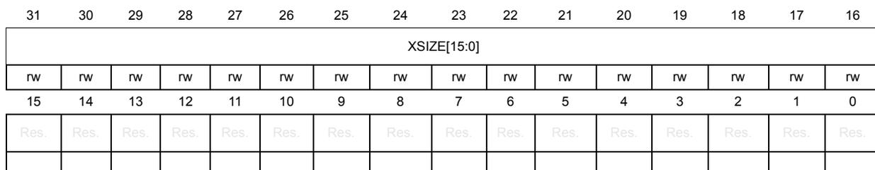
35.5.4 JPEG codec configuration register 3 (JPEG_CONFR3)
Address offset: 0x00C
Reset value: 0x0000 0000
| 31 | 30 | 29 | 28 | 27 | 26 | 25 | 24 | 23 | 22 | 21 | 20 | 19 | 18 | 17 | 16 |
| XSIZE[15:0] | |||||||||||||||
| rw | rw | rw | rw | rw | rw | rw | rw | rw | rw | rw | rw | rw | rw | rw | rw |
| 15 | 14 | 13 | 12 | 11 | 10 | 9 | 8 | 7 | 6 | 5 | 4 | 3 | 2 | 1 | 0 |
| Res. | Res. | Res. | Res. | Res. | Res. | Res. | Res. | Res. | Res. | Res. | Res. | Res. | Res. | Res. | Res. |
Bits 31:16 XSIZE[15:0] : X size
This field defines the number of pixels per line.
Bits 15:0 Reserved, must be kept at reset value.
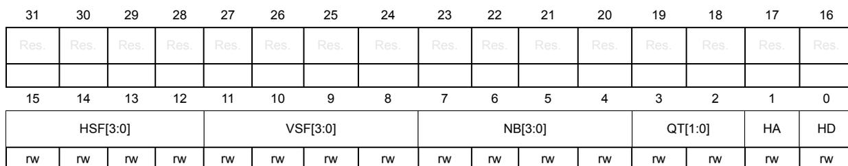
35.5.5 JPEG codec configuration register x (JPEG_CONFRx)
Address offset: 0x000 + 0x4 * x, (x = 4 to 7)
Reset value: 0x0000 0000
| 31 | 30 | 29 | 28 | 27 | 26 | 25 | 24 | 23 | 22 | 21 | 20 | 19 | 18 | 17 | 16 |
| Res. | Res. | Res. | Res. | Res. | Res. | Res. | Res. | Res. | Res. | Res. | Res. | Res. | Res. | Res. | Res. |
| 15 | 14 | 13 | 12 | 11 | 10 | 9 | 8 | 7 | 6 | 5 | 4 | 3 | 2 | 1 | 0 |
| HSF[3:0] | VSF[3:0] | NB[3:0] | QT[1:0] | HA | HD | ||||||||||
| rw | rw | rw | rw | rw | rw | rw | rw | rw | rw | rw | rw | rw | rw | rw | rw |
Bits 31:16 Reserved, must be kept at reset value.
Bits 15:12 HSF[3:0] : Horizontal sampling factor
Horizontal sampling factor for component {x-4}.
Bits 11:8 VSF[3:0] : Vertical sampling factor
Vertical sampling factor for component {x-4}.
Bits 7:4 NB[3:0] : Number of blocks
Number of data units minus 1 that belong to a particular color in the MCU.
Bits 3:2 QT[1:0] : Quantization table
Selects quantization table used for component {x-4}.
00: Quantization table 0
01: Quantization table 1
10: Quantization table 2
11: Quantization table 3
Bit 1 HA : Huffman AC
Selects the Huffman table for encoding AC coefficients.
0: Huffman AC table 0
1: Huffman AC table 1
Bit 0 HD : Huffman DC
Selects the Huffman table for encoding DC coefficients.
0: Huffman DC table 0
1: Huffman DC table 1
35.5.6 JPEG control register (JPEG_CR)
Address offset: 0x030
Reset value: 0x0000 0000
| 31 | 30 | 29 | 28 | 27 | 26 | 25 | 24 | 23 | 22 | 21 | 20 | 19 | 18 | 17 | 16 |
|---|---|---|---|---|---|---|---|---|---|---|---|---|---|---|---|
| Res. | Res. | Res. | Res. | Res. | Res. | Res. | Res. | Res. | Res. | Res. | Res. | Res. | Res. | Res. | Res. |
| 15 | 14 | 13 | 12 | 11 | 10 | 9 | 8 | 7 | 6 | 5 | 4 | 3 | 2 | 1 | 0 |
| Res. | OFF | IFF | Res. | Res. | Res. | Res. | Res. | Res. | HPDIE | EOCIE | OFNEIE | OFTIE | IFNFIE | IFTIE | JCEN |
| w | w | rw | rw | rw | rw | rw | rw | rw |
Bits 31:15 Reserved, must be kept at reset value.
Bit 14 OFF : Output FIFO flush
This bit flushes the output FIFO.
0: No effect
1: Output FIFO is flushed
Note: Reads always return 0.
Bit 13 IFF : Input FIFO flush
This bit flushes the input FIFO.
0: No effect
1: Input FIFO is flushed
Note: Reads always return 0.
Bits 12:7 Reserved, must be kept at reset value.
Bit 6 HPDIE : Header parsing done interrupt enable
This bit enables interrupt generation upon the completion of the header parsing operation.
0: Disabled
1: Enabled
Bit 5 EOCIE : End of conversion interrupt enable
This bit enables interrupt generation at the end of conversion.
0: Disabled
1: Enabled
Bit 4 OFNEIE : Output FIFO not empty interrupt enable
This bit enables interrupt generation when the output FIFO is not empty.
0: Disabled
1: Enabled
Bit 3 OFTIE : Output FIFO threshold interrupt enable
This bit enables interrupt generation when the output FIFO reaches a threshold.
0: Disabled
1: Enabled
Bit 2 IFNFIE : Input FIFO not full interrupt enable
This bit enables interrupt generation when the input FIFO is not empty.
0: Disabled
1: Enabled
Bit 1 IFTIE : Input FIFO threshold interrupt enable
This bit enables interrupt generation when the input FIFO reaches a threshold.
0: Disabled
1: Enabled
Bit 0 JCEN : JPEG core enable
This bit enables the JPEG codec core.
0: Disabled (internal registers are reset).
1: Enabled (internal registers are accessible).
35.5.7 JPEG status register (JPEG_SR)
Address offset: 0x034
Reset value: 0x0000 0006
| 31 | 30 | 29 | 28 | 27 | 26 | 25 | 24 | 23 | 22 | 21 | 20 | 19 | 18 | 17 | 16 |
|---|---|---|---|---|---|---|---|---|---|---|---|---|---|---|---|
| Res. | Res. | Res. | Res. | Res. | Res. | Res. | Res. | Res. | Res. | Res. | Res. | Res. | Res. | Res. | Res. |
| 15 | 14 | 13 | 12 | 11 | 10 | 9 | 8 | 7 | 6 | 5 | 4 | 3 | 2 | 1 | 0 |
| Res. | Res. | Res. | Res. | Res. | Res. | Res. | Res. | COF | HPDF | EOCF | OFNEF | OFTF | IFNFF | IFTF | Res. |
| r | r | r | r | r | r | r |
Bits 31:8 Reserved, must be kept at reset value.
Bit 7 COF : Codec operation flag
This bit flags code/decode operation in progress.
0: Not in progress
1: In progress
Bit 6 HPDF : Header parsing done flag
In decode mode, this bit flags the completion of header parsing and updating internal registers.
0: Not completed
1: Completed
Bit 5 EOCF : End of conversion flag
This bit flags the completion of encode/decode process and data transfer to the output FIFO.
0: Not completed
1: Completed
- Bit 4
OFNEF
: Output FIFO not empty flag
This bit flags that data is available in the output FIFO.
0: Empty (data not available)
1: Not empty (data available) - Bit 3
OFTF
: Output FIFO threshold flag
This bit flags that the amount of data in the output FIFO reaches or exceeds a threshold.
0: Below threshold
1: At or above threshold - Bit 2
IFNFF
: Input FIFO not full flag
This bit flags that the input FIFO is not full (data can be written).
0: Full
1: Not full - Bit 1
IFTF
: Input FIFO threshold flag
This bit flags that the amount of data in the input FIFO is below a threshold.
0: At or above threshold
1: Below threshold. - Bit 0 Reserved, must be kept at reset value.
35.5.8 JPEG clear flag register (JPEG_CFR)
Address offset: 0x038
Reset value: 0x0000 0000
| 31 | 30 | 29 | 28 | 27 | 26 | 25 | 24 | 23 | 22 | 21 | 20 | 19 | 18 | 17 | 16 |
|---|---|---|---|---|---|---|---|---|---|---|---|---|---|---|---|
| Res. | Res. | Res. | Res. | Res. | Res. | Res. | Res. | Res. | Res. | Res. | Res. | Res. | Res. | Res. | Res. |
| 15 | 14 | 13 | 12 | 11 | 10 | 9 | 8 | 7 | 6 | 5 | 4 | 3 | 2 | 1 | 0 |
| Res. | Res. | Res. | Res. | Res. | Res. | Res. | Res. | Res. | CHPDF | CEOCF | Res. | Res. | Res. | Res. | Res. |
| rt_w1 | rt_w1 |
- Bits 31:7 Reserved, must be kept at reset value.
- Bit 6
CHPDF
: Clear header parsing done flag
Writing 1 clears the HPDF bit of the JPEG_SR register.
0: No effect
1: Clear - Bit 5
CEOCF
: Clear end of conversion flag
Writing 1 clears the ECF bit of the JPEG_SR register.
0: No effect
1: Clear - Bits 4:0 Reserved, must be kept at reset value.
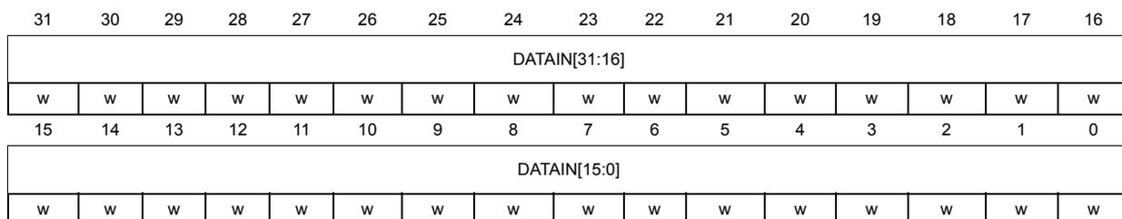
35.5.9 JPEG data input register (JPEG_DIR)
Address offset: 0x040
Reset value: 0x0000 0000
| 31 | 30 | 29 | 28 | 27 | 26 | 25 | 24 | 23 | 22 | 21 | 20 | 19 | 18 | 17 | 16 |
| DATAIN[31:16] | |||||||||||||||
| w | w | w | w | w | w | w | w | w | w | w | w | w | w | w | w |
| 15 | 14 | 13 | 12 | 11 | 10 | 9 | 8 | 7 | 6 | 5 | 4 | 3 | 2 | 1 | 0 |
| DATAIN[15:0] | |||||||||||||||
| w | w | w | w | w | w | w | w | w | w | w | w | w | w | w | w |
Bits 31:0
DATAIN[31:0]
: Data input FIFO
Input FIFO data register
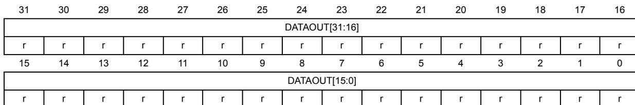
35.5.10 JPEG data output register (JPEG_DOR)
Address offset: 0x044
Reset value: 0x0000 0000
| 31 | 30 | 29 | 28 | 27 | 26 | 25 | 24 | 23 | 22 | 21 | 20 | 19 | 18 | 17 | 16 |
| DATAOUT[31:16] | |||||||||||||||
| r | r | r | r | r | r | r | r | r | r | r | r | r | r | r | r |
| 15 | 14 | 13 | 12 | 11 | 10 | 9 | 8 | 7 | 6 | 5 | 4 | 3 | 2 | 1 | 0 |
| DATAOUT[15:0] | |||||||||||||||
| r | r | r | r | r | r | r | r | r | r | r | r | r | r | r | r |
Bits 31:0
DATAOUT[31:0]
: Data output FIFO
Output FIFO data register.
35.5.11 JPEG quantization memory x (JPEG_QMEMx_y)
Address offset: 0x050 + 0x40 * x + 0x4 * y, (x = 0 to 3; y = 0 to 15)
Reset value: 0xXXXX XXXX
Four quantization tables as specified by ISO documentation.
For decoding with header parsing, no quantization table programming is required, the coefficients are directly written in the quantization memories by header parser.
For decoding without header parsing or for encoding, the quantization table must be written by software in zig zag order.
| 31 | 30 | 29 | 28 | 27 | 26 | 25 | 24 | 23 | 22 | 21 | 20 | 19 | 18 | 17 | 16 |
| QCOEF{4*y+3}[7:0] | QCOEF{4*y+2}[7:0] | ||||||||||||||
| rw | rw | rw | rw | rw | rw | rw | rw | rw | rw | rw | rw | rw | rw | rw | rw |
| 15 | 14 | 13 | 12 | 11 | 10 | 9 | 8 | 7 | 6 | 5 | 4 | 3 | 2 | 1 | 0 |
| QCOEF{4*y+1}[7:0] | QCOEF{4*y}[7:0] | ||||||||||||||
| rw | rw | rw | rw | rw | rw | rw | rw | rw | rw | rw | rw | rw | rw | rw | rw |
Bits 31:24
QCOEF{4*y+3}[7:0]
: Quantization coefficient {4*y+3}
8-bit quantization coefficient.
Bits 23:16
QCOEF{4*y+2}[7:0]
: Quantization coefficient {4*y+2}
8-bit quantization coefficient.
Bits 15:8
QCOEF{4*y+1}[7:0]
: Quantization coefficient {4*y+1}
8-bit quantization coefficient.
Bits 7:0
QCOEF{4*y}[7:0]
: Quantization coefficient {4*y}
8-bit quantization coefficient.
35.5.12 JPEG Huffman min (JPEG_HUFFMINx_y)
Address offset: 0x150 + 0x10 * x + 0x4 * y, (x = 0 to 3; y = 0 to 2)
Reset value: 0xXXXX XXXX
This memory stores the minimum Huffman values used internally by the JPEG decoder. The memory content is written by hardware during the header parsing.
- • DATA0: Min AC0 value
- • DATA1: Min DC0 value
- • DATA2: Min AC1 value
- • DATA3: Min DC1 value
| 31 | 30 | 29 | 28 | 27 | 26 | 25 | 24 | 23 | 22 | 21 | 20 | 19 | 18 | 17 | 16 |
| DATA{x}{[32*y+31]:[32*y+16]} | |||||||||||||||
| rw | rw | rw | rw | rw | rw | rw | rw | rw | rw | rw | rw | rw | rw | rw | rw |
| 15 | 14 | 13 | 12 | 11 | 10 | 9 | 8 | 7 | 6 | 5 | 4 | 3 | 2 | 1 | 0 |
| DATA{x}{[32*y+15]:[32*y]} | |||||||||||||||
| rw | rw | rw | rw | rw | rw | rw | rw | rw | rw | rw | rw | rw | rw | rw | rw |
Bits 31:0
DATA{x}[{32*y+31}:{32*y}]
: Minimum Huffman value
100-bit minimum Huffman value used internally by the JPEG decoder.
35.5.13 JPEG Huffman min x (JPEG_HUFFMINx_y)
Address offset: \( 0x150 + 0x10 * x + 0x4 * y \) , ( \( x = 0 \) to \( 3 \) ; \( y = 3 \) )
Reset value: 0xXXXX XXXX
This memory stores the minimum Huffman values used internally by the JPEG decoder. The memory content is written by hardware during the header parsing.
- • DATA0: Min AC0 value
- • DATA1: Min DC0 value
- • DATA2: Min AC1 value
- • DATA3: Min DC1 value
| 31 | 30 | 29 | 28 | 27 | 26 | 25 | 24 | 23 | 22 | 21 | 20 | 19 | 18 | 17 | 16 |
|---|---|---|---|---|---|---|---|---|---|---|---|---|---|---|---|
| Res. | Res. | Res. | Res. | Res. | Res. | Res. | Res. | Res. | Res. | Res. | Res. | Res. | Res. | Res. | Res. |
| 15 | 14 | 13 | 12 | 11 | 10 | 9 | 8 | 7 | 6 | 5 | 4 | 3 | 2 | 1 | 0 |
| Res. | Res. | Res. | Res. | Res. | Res. | Res. | Res. | Res. | Res. | Res. | Res. | DATA{x}[99:96] | |||
| rw | rw | rw | rw | ||||||||||||
Bits 31:4 Reserved, must be kept at reset value.
Bits 3:0
DATA{x}[99:96]
: Minimum Huffman value
100-bit minimum Huffman value used internally by the JPEG decoder.
35.5.14 JPEG Huffman base (JPEG_HUFFBASEx)
Address offset: \( 0x190 + 0x4 * x \) , ( \( x = 0 \) to \( 31 \) )
Reset value: 0xXXXX XXXX
This memory stores the base Huffman values used internally by the JPEG decoder. The memory content is written by hardware during the header parsing:
- • DATA0 to DATA15: Base AC0 value
- • DATA16 to DATA31: Base DC0 value
- • DATA32 to DATA47: Base AC1 value
- • DATA48 to DATA63: Base DC1 value
| 31 | 30 | 29 | 28 | 27 | 26 | 25 | 24 | 23 | 22 | 21 | 20 | 19 | 18 | 17 | 16 |
|---|---|---|---|---|---|---|---|---|---|---|---|---|---|---|---|
| Res. | Res. | Res. | Res. | Res. | Res. | Res. | DATA{2*x+1}[8:0] | ||||||||
| rw | rw | rw | rw | rw | rw | rw | rw | rw | |||||||
| 15 | 14 | 13 | 12 | 11 | 10 | 9 | 8 | 7 | 6 | 5 | 4 | 3 | 2 | 1 | 0 |
| Res. | Res. | Res. | Res. | Res. | Res. | Res. | DATA{2*x}[8:0] | ||||||||
| rw | rw | rw | rw | rw | rw | rw | rw | rw | |||||||
Bits 31:25 Reserved, must be kept at reset value.
Bits 24:16
DATA{2*x+1}[8:0]
: Data {2*x+1}
Base Huffman value.
Bits 15:9 Reserved, must be kept at reset value.
Bits 8:0
DATA{2*x}[8:0]
: Data {2*x}
Base Huffman value.
35.5.15 JPEG Huffman symbol (JPEG_HUFFSYMBx)
Address offset: 0x210 + 0x4 * x, (x = 0 to 83)
Reset value: 0xXXXX XXXX
This memory stores the Huffman symbols used internally by the JPEG decoder. The memory content is written by hardware during the header parsing:
- • DATA0 to DATA161: AC0 symbols
- • DATA162 to DATA173: DC0 and DC1 symbols
- • DATA174 to DATA335: AC1 symbols
| 31 | 30 | 29 | 28 | 27 | 26 | 25 | 24 | 23 | 22 | 21 | 20 | 19 | 18 | 17 | 16 |
|---|---|---|---|---|---|---|---|---|---|---|---|---|---|---|---|
| DATA{4*x+3}[7:0] | DATA{4*x+2}[7:0] | ||||||||||||||
| rw | rw | rw | rw | rw | rw | rw | rw | rw | rw | rw | rw | rw | rw | rw | rw |
| 15 | 14 | 13 | 12 | 11 | 10 | 9 | 8 | 7 | 6 | 5 | 4 | 3 | 2 | 1 | 0 |
| DATA{4*x+1}[7:0] | DATA{4*x}[7:0] | ||||||||||||||
| rw | rw | rw | rw | rw | rw | rw | rw | rw | rw | rw | rw | rw | rw | rw | rw |
Bits 31:24
DATA{4*x+3}[7:0]
: Data {4*x+3}
Huffman symbol.
Bits 23:16
DATA{4*x+2}[7:0]
: Data {4*x+2}
Huffman symbol.
Bits 15:8
DATA{4*x+1}[7:0]
: Data {4*x+1}
Huffman symbol.
Bits 7:0
DATA{4*x}[7:0]
: Data {4*x}
Huffman symbol.
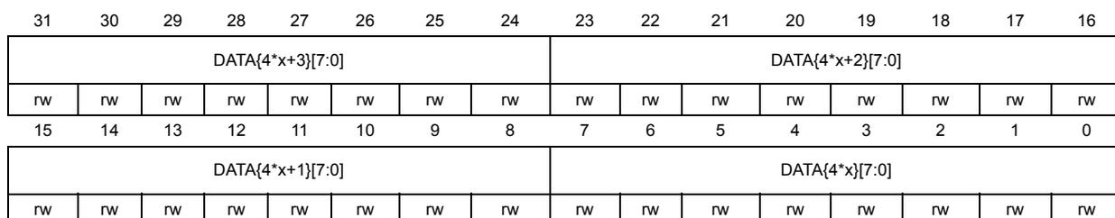
35.5.16 JPEG DHT memory (JPEG_DHTMEMx)
Address offset: \( 0x360 + 0x4 \times x \) , ( \( x = 0 \) to 102)
Reset value: 0xXXXX XXXX
For encoding process with header generation, this memory stores the DHT marker segment AC and DC Huffman tables in the ISO/IEC specification format:
- • DATA0 to DATA27: DC Huffman table0
- • DATA28 to DATA205: AC Huffman table0
- • DATA206 to DATA233: DC Huffman table1
- • DATA234 to DATA411: AC Huffman table1
| 31 | 30 | 29 | 28 | 27 | 26 | 25 | 24 | 23 | 22 | 21 | 20 | 19 | 18 | 17 | 16 |
| DATA{4*x+3}[7:0] | DATA{4*x+2}[7:0] | ||||||||||||||
| rw | rw | rw | rw | rw | rw | rw | rw | rw | rw | rw | rw | rw | rw | rw | rw |
| 15 | 14 | 13 | 12 | 11 | 10 | 9 | 8 | 7 | 6 | 5 | 4 | 3 | 2 | 1 | 0 |
| DATA{4*x+1}[7:0] | DATA{4*x}[7:0] | ||||||||||||||
| rw | rw | rw | rw | rw | rw | rw | rw | rw | rw | rw | rw | rw | rw | rw | rw |
Bits 31:24
DATA{4*x+3}[7:0]
: Huffman table data {4*x+3}
Huffman table data for DHT marker segment generation.
Bits 23:16
DATA{4*x+2}[7:0]
: Huffman table data {4*x+2}
Huffman table data for DHT marker segment generation.
Bits 15:8
DATA{4*x+1}[7:0]
: Huffman table data {4*x+1}
Huffman table data for DHT marker segment generation.
Bits 7:0
DATA{4*x}[7:0]
: Huffman table data {4*x}
Huffman table data for DHT marker segment generation.
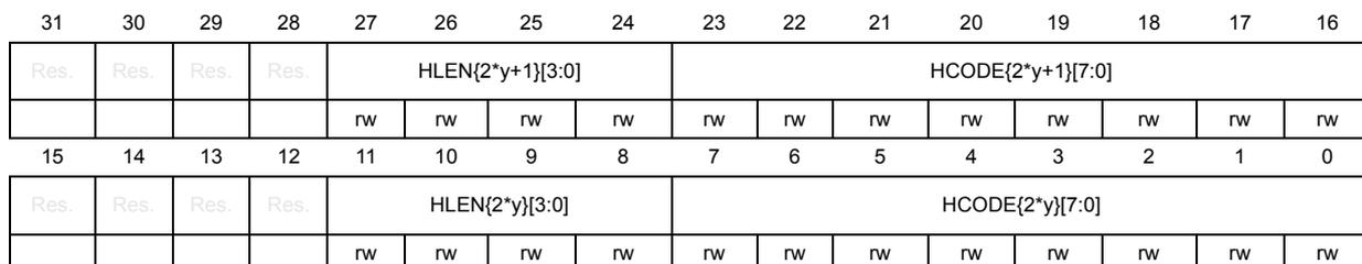
35.5.17 JPEG Huffman encoder ACx (JPEG_HUFFENC_ACx_y)
Address offset: \( 0x500 + 0x160 \times x + 0x4 \times y \) , ( \( x = 0 \) to 1; \( y = 0 \) to 87)
Reset value: 0xXXXX XXXX
This memory defines the Huffman codes used during the encoding process of AC components.
| 31 | 30 | 29 | 28 | 27 | 26 | 25 | 24 | 23 | 22 | 21 | 20 | 19 | 18 | 17 | 16 |
| Res. | Res. | Res. | Res. | HLEN{2*y+1}[3:0] | HCODE{2*y+1}[7:0] | ||||||||||
| rw | rw | rw | rw | rw | rw | rw | rw | rw | rw | rw | rw | ||||
| 15 | 14 | 13 | 12 | 11 | 10 | 9 | 8 | 7 | 6 | 5 | 4 | 3 | 2 | 1 | 0 |
| Res. | Res. | Res. | Res. | HLEN{2*y}[3:0] | HCODE{2*y}[7:0] | ||||||||||
| rw | rw | rw | rw | rw | rw | rw | rw | rw | rw | rw | rw | ||||
Bits 31:28 Reserved, must be kept at reset value.
- Bits 27:24
HLEN{2*y+1}[3:0]
: Huffman length {2*y+1}
Number of bits in the Huffman code HCODE{2*y+1} minus 1. - Bits 23:16
HCODE{2*y+1}[7:0]
: Huffman code {2*y+1}
8 least significant bits of the Huffman code.
If the Huffman code is less than 8 bits long, the unused bits must be 0. - Bits 15:12 Reserved, must be kept at reset value.
- Bits 11:8
HLEN{2*y}[3:0]
: Huffman length {2*y}
Number of bits in the Huffman code HCODE{2*y} minus 1. - Bits 7:0
HCODE{2*y}[7:0]
: Huffman code {2*y}
8 least significant bits of the Huffman code.
If the Huffman code is less than 8 bits long, the unused bits must be 0.
35.5.18 JPEG Huffman encoder DCx (JPEG_HUFFENC_DCx_y)
Address offset: 0x7C0 + 0x20*x + 0x4*y, (x = 0 to 1; y = 0 to 7)
Reset value: 0xXXXX XXXX
This memory defines the Huffman codes used during the encoding process of DC components.
| 31 | 30 | 29 | 28 | 27 | 26 | 25 | 24 | 23 | 22 | 21 | 20 | 19 | 18 | 17 | 16 |
|---|---|---|---|---|---|---|---|---|---|---|---|---|---|---|---|
| Res. | Res. | Res. | Res. | HLEN{2*y+1}[3:0] | HCODE{2*y+1}[7:0] | ||||||||||
| rw | rw | rw | rw | rw | rw | rw | rw | rw | rw | rw | rw | ||||
| 15 | 14 | 13 | 12 | 11 | 10 | 9 | 8 | 7 | 6 | 5 | 4 | 3 | 2 | 1 | 0 |
| Res. | Res. | Res. | Res. | HLEN{2*y}[3:0] | HCODE{2*y}[7:0] | ||||||||||
| rw | rw | rw | rw | rw | rw | rw | rw | rw | rw | rw | rw | ||||
- Bits 31:28 Reserved, must be kept at reset value.
- Bits 27:24
HLEN{2*y+1}[3:0]
: Huffman length {2*y+1}
Number of bits in the Huffman code HCODE{2*y+1} minus 1. - Bits 23:16
HCODE{2*y+1}[7:0]
: Huffman code {2*y+1}
8 least significant bits of the Huffman code.
If the Huffman code is less than 8 bits long, the unused bits must be 0. - Bits 15:12 Reserved, must be kept at reset value.
- Bits 11:8
HLEN{2*y}[3:0]
: Huffman length {2*y}
Number of bits in the Huffman code HCODE{2*y} minus 1. - Bits 7:0
HCODE{2*y}[7:0]
: Huffman code {2*y}
8 least significant bits of the Huffman code.
If the Huffman code is less than 8 bits long, the unused bits must be 0.
35.5.19 JPEG codec register map
The following table summarizes the JPEG codec registers. Refer to the register boundary addresses table for the JPEG codec register base address.
Table 297. JPEG codec register map and reset values
| Offset | Register name | 31 | 30 | 29 | 28 | 27 | 26 | 25 | 24 | 23 | 22 | 21 | 20 | 19 | 18 | 17 | 16 | 15 | 14 | 13 | 12 | 11 | 10 | 9 | 8 | 7 | 6 | 5 | 4 | 3 | 2 | 1 | 0 |
|---|---|---|---|---|---|---|---|---|---|---|---|---|---|---|---|---|---|---|---|---|---|---|---|---|---|---|---|---|---|---|---|---|---|
| 0x000 | JPEG_CONFR0 | Res. | Res. | Res. | Res. | Res. | Res. | Res. | Res. | Res. | Res. | Res. | Res. | Res. | Res. | Res. | Res. | Res. | Res. | Res. | Res. | Res. | Res. | Res. | Res. | Res. | Res. | Res. | Res. | Res. | Res. | Res. | START |
| Reset value | 0 | ||||||||||||||||||||||||||||||||
| 0x004 | JPEG_CONFR1 | YSIZE[15:0] | Res. | Res. | Res. | Res. | Res. | Res. | HDR | NS[1:0] | COLSPACE [1:0] | DE | Res. | NF[1:0] | |||||||||||||||||||
| Reset value | 0 | 0 | 0 | 0 | 0 | 0 | 0 | 0 | 0 | 0 | 0 | 0 | 0 | 0 | 0 | 0 | 0 | 0 | 0 | 0 | 0 | 0 | 0 | 0 | 0 | ||||||||
| 0x008 | JPEG_CONFR2 | Res. | Res. | Res. | Res. | Res. | Res. | NMCU[25:0] | |||||||||||||||||||||||||
| Reset value | 0 | 0 | 0 | 0 | 0 | 0 | 0 | 0 | 0 | 0 | 0 | 0 | 0 | 0 | 0 | 0 | 0 | 0 | 0 | 0 | 0 | 0 | 0 | 0 | 0 | 0 | |||||||
| 0x00C | JPEG_CONFR3 | XSIZE[15:0] | Res. | Res. | Res. | Res. | Res. | Res. | Res. | Res. | Res. | Res. | Res. | Res. | Res. | Res. | Res. | Res. | |||||||||||||||
| Reset value | 0 | 0 | 0 | 0 | 0 | 0 | 0 | 0 | 0 | 0 | 0 | 0 | 0 | 0 | 0 | 0 | |||||||||||||||||
| 0x010 | JPEG_CONFR4 | Res. | Res. | Res. | Res. | Res. | Res. | Res. | Res. | Res. | Res. | Res. | Res. | Res. | Res. | Res. | Res. | HSF[3:0] | VSF[3:0] | NB[3:0] | QT[1:0] | HA | HD | ||||||||||
| Reset value | 0 | 0 | 0 | 0 | 0 | 0 | 0 | 0 | 0 | 0 | 0 | 0 | 0 | 0 | 0 | 0 | |||||||||||||||||
| 0x014 | JPEG_CONFR5 | Res. | Res. | Res. | Res. | Res. | Res. | Res. | Res. | Res. | Res. | Res. | Res. | Res. | Res. | Res. | Res. | HSF[3:0] | VSF[3:0] | NB[3:0] | QT[1:0] | HA | HD | ||||||||||
| Reset value | 0 | 0 | 0 | 0 | 0 | 0 | 0 | 0 | 0 | 0 | 0 | 0 | 0 | 0 | 0 | 0 | |||||||||||||||||
| 0x018 | JPEG_CONFR6 | Res. | Res. | Res. | Res. | Res. | Res. | Res. | Res. | Res. | Res. | Res. | Res. | Res. | Res. | Res. | Res. | HSF[3:0] | VSF[3:0] | NB[3:0] | QT[1:0] | HA | HD | ||||||||||
| Reset value | 0 | 0 | 0 | 0 | 0 | 0 | 0 | 0 | 0 | 0 | 0 | 0 | 0 | 0 | 0 | 0 | |||||||||||||||||
| 0x01C | JPEG_CONFR7 | Res. | Res. | Res. | Res. | Res. | Res. | Res. | Res. | Res. | Res. | Res. | Res. | Res. | Res. | Res. | Res. | HSF[3:0] | VSF[3:0] | NB[3:0] | QT[1:0] | HA | HD | ||||||||||
| Reset value | 0 | 0 | 0 | 0 | 0 | 0 | 0 | 0 | 0 | 0 | 0 | 0 | 0 | 0 | 0 | 0 | |||||||||||||||||
| 0x020-0x02C | Reserved | Reserved | |||||||||||||||||||||||||||||||
| 0x030 | JPEG_CR | Res. | Res. | Res. | Res. | Res. | Res. | Res. | Res. | Res. | Res. | Res. | Res. | Res. | Res. | Res. | Res. | OFF | IFF | Res. | Res. | Res. | Res. | Res. | Res. | HPDIE | EOCIE | OFNEIE | OFTEIE | IFNIE | IFTIE | JCEN | Res. |
| Reset value | 0 | 0 | 0 | 0 | 0 | 0 | 0 | 0 | 0 | ||||||||||||||||||||||||
| 0x034 | JPEG_SR | Res. | Res. | Res. | Res. | Res. | Res. | Res. | Res. | Res. | Res. | Res. | Res. | Res. | Res. | Res. | Res. | Res. | Res. | Res. | Res. | Res. | Res. | Res. | COF | HPDF | EOCF | OFNEF | OFTEF | IFNEF | IFTIF | Res. | Res. |
| Reset value | 0 | 0 | 0 | 0 | 0 | 1 | 1 | ||||||||||||||||||||||||||
| 0x038 | JPEG_CFR | Res. | Res. | Res. | Res. | Res. | Res. | Res. | Res. | Res. | Res. | Res. | Res. | Res. | Res. | Res. | Res. | Res. | Res. | Res. | Res. | Res. | Res. | Res. | CHPDF | CEOCF | Res. | Res. | Res. | Res. | Res. | Res. | Res. |
| Reset value | 0 | 0 | |||||||||||||||||||||||||||||||
| 0x040 | JPEG_DIR | DATAIN[31:0] | |||||||||||||||||||||||||||||||
| Reset value | 0 | 0 | 0 | 0 | 0 | 0 | 0 | 0 | 0 | 0 | 0 | 0 | 0 | 0 | 0 | 0 | 0 | 0 | 0 | 0 | 0 | 0 | 0 | 0 | 0 | 0 | 0 | 0 | 0 | 0 | 0 | 0 | |
| 0x044 | JPEG_DOR | DATAOUT[31:0] | |||||||||||||||||||||||||||||||
| Reset value | 0 | 0 | 0 | 0 | 0 | 0 | 0 | 0 | 0 | 0 | 0 | 0 | 0 | 0 | 0 | 0 | 0 | 0 | 0 | 0 | 0 | 0 | 0 | 0 | 0 | 0 | 0 | 0 | 0 | 0 | 0 | 0 | |
| 0x048-0x04C | Reserved | Reserved | |||||||||||||||||||||||||||||||
| 0x050-0x08C | JPEG_QMEM0 | QCOEF{4*y+3}[7:0] | QCOEF{4*y+2}[7:0] | QCOEF{4*y+1}[7:0] | QCOEF{4*y}[7:0] | ||||||||||||||||||||||||||||
| Reset value | X | X | X | X | X | X | X | X | X | X | X | X | X | X | X | X | X | X | X | X | X | X | X | X | X | X | X | X | X | X | X | X | |
Table 297. JPEG codec register map and reset values (continued)
| Offset | Register name | 31 | 30 | 29 | 28 | 27 | 26 | 25 | 24 | 23 | 22 | 21 | 20 | 19 | 18 | 17 | 16 | 15 | 14 | 13 | 12 | 11 | 10 | 9 | 8 | 7 | 6 | 5 | 4 | 3 | 2 | 1 | 0 | |
|---|---|---|---|---|---|---|---|---|---|---|---|---|---|---|---|---|---|---|---|---|---|---|---|---|---|---|---|---|---|---|---|---|---|---|
| 0x090-0x0CC | JPEG_QMEM1 | QCOEF{4*y+3}[7:0] | QCOEF{4*y+2}[7:0] | QCOEF{4*y+1}[7:0] | QCOEF{4*y}[7:0] | |||||||||||||||||||||||||||||
| Reset value | X | X | X | X | X | X | X | X | X | X | X | X | X | X | X | X | X | X | X | X | X | X | X | X | X | X | X | X | X | X | X | X | ||
| 0x0D0-0x10F | JPEG_QMEM2 | QCOEF{4*y+3}[7:0] | QCOEF{4*y+2}[7:0] | QCOEF{4*y+1}[7:0] | QCOEF{4*y}[7:0] | |||||||||||||||||||||||||||||
| Reset value | X | X | X | X | X | X | X | X | X | X | X | X | X | X | X | X | X | X | X | X | X | X | X | X | X | X | X | X | X | X | X | X | ||
| 0x110-0x14C | JPEG_QMEM3 | QCOEF{4*y+3}[7:0] | QCOEF{4*y+2}[7:0] | QCOEF{4*y+1}[7:0] | QCOEF{4*y}[7:0] | |||||||||||||||||||||||||||||
| Reset value | X | X | X | X | X | X | X | X | X | X | X | X | X | X | X | X | X | X | X | X | X | X | X | X | X | X | X | X | X | X | X | X | ||
| 0x150-0x18C | JPEG_HUFFMIN | Res | Res | Res | Res | Res | Res | Res | Res | Res | Res | Res | Res | Res | Res | Res | Res | Res | Res | Res | Res | Res | Res | Res | Res | Res | Res | Res | Res | Res | Res | Res | DATA{x}[99:96] | |
| DATA{x}[95:64] | ||||||||||||||||||||||||||||||||||
| DATA{x}[63:32] | ||||||||||||||||||||||||||||||||||
| Reset value | X | X | X | X | X | X | X | X | X | X | X | X | X | X | X | X | X | X | X | X | X | X | X | X | X | X | X | X | X | X | X | X | ||
| 0x190-0x20C | JPEG_HUFFBASE | Res | Res | Res | Res | Res | Res | Res | Res | Res | Res | Res | Res | Res | Res | Res | Res | Res | Res | Res | Res | Res | Res | Res | Res | Res | Res | Res | Res | Res | Res | Res | DATA{2*x}[8:0] | |
| Reset value | X | X | X | X | X | X | X | X | X | X | X | X | X | X | X | X | X | X | X | X | X | X | X | X | ||||||||||
| 0x210-0x35C | JPEG_HUFFSYMB | DATA{4*x+3}[7:0] | DATA{4*x+2}[7:0] | DATA{4*x+1}[7:0] | DATA{4*x}[7:0] | |||||||||||||||||||||||||||||
| Reset value | X | X | X | X | X | X | X | X | X | X | X | X | X | X | X | X | X | X | X | X | X | X | X | X | X | X | X | X | X | X | X | X | ||
| 0x360-0x4F8 | JPEG_DHTMEM | DATA{4*x+3}[7:0] | DATA{4*x+2}[7:0] | DATA{4*x+1}[7:0] | DATA{4*x}[7:0] | |||||||||||||||||||||||||||||
| Reset value | X | X | X | X | X | X | X | X | X | X | X | X | X | X | X | X | X | X | X | X | X | X | X | X | X | X | X | X | X | X | X | X | ||
| 0x4FC | Reserved | Res | ||||||||||||||||||||||||||||||||
| 0x500-0x65C | JPEG_HUFFENC_AC0 | Res | Res | Res | Res | Res | Res | Res | Res | Res | Res | Res | Res | Res | Res | Res | Res | Res | Res | Res | Res | Res | Res | Res | Res | Res | Res | Res | Res | Res | Res | Res | Res | |
| Reset value | ||||||||||||||||||||||||||||||||||
| 0x660-0x7BC | JPEG_HUFFENC_AC1 | Res | Res | Res | Res | Res | Res | Res | Res | Res | Res | Res | Res | Res | Res | Res | Res | Res | Res | Res | Res | Res | Res | Res | Res | Res | Res | Res | Res | Res | Res | Res | Res | |
| Reset value | ||||||||||||||||||||||||||||||||||
| 0x7C0-0x7DC | JPEG_HUFFENC_DC0 | Res | Res | Res | Res | Res | Res | Res | Res | Res | Res | Res | Res | Res | Res | Res | Res | Res | Res | Res | Res | Res | Res | Res | Res | Res | Res | Res | Res | Res | Res | Res | Res | |
| Reset value | ||||||||||||||||||||||||||||||||||
| 0x7E0-0x7FC | JPEG_HUFFENC_DC1 | Res | Res | Res | Res | Res | Res | Res | Res | Res | Res | Res | Res | Res | Res | Res | Res | Res | Res | Res | Res | Res | Res | Res | Res | Res | Res | Res | Res | Res | Res | Res | Res | |
| Reset value | ||||||||||||||||||||||||||||||||||
Refer to Section 2.3 for the register boundary addresses.