5. Secure memory management (SMM)
5.1 Introduction
STM32H755xl and STM32H757xl microcontrollers offer a first set of protection mechanisms, which are similar to other STM32 Series:
- • Global readout device protection (RDP)
- • Write protection (WRP)
- • Proprietary code readout protection (PCROP)
A detailed description of these protection mechanisms is given in Section 4: Embedded flash memory (FLASH) .
STM32H755xl and STM32H757xl also offer an additional enhanced protection mode, the Secure access mode, that makes possible the development of user-defined secure services (e.g. secure firmware update or secure boot) and guarantees of a safe execution and protection of both code and data. This mechanism is described in details in Section 5.3: Secure access mode , Section 5.4: Root secure services (RSS) and Section 5.5: Secure user software .
The secure memory management unit is contained inside the D1 domain. It is assumed that any code subject to confidentiality protection will be executed by the Cortex-M7 only.
5.2 Glossary
The following terms will be used in herein:
Table 28. List of preferred terms
| Term | Description |
|---|---|
| Device Security Level | |
| Standard mode | Device state which allows the access to the user Flash memory, the option bytes and the bootloader area. |
| Secure access mode | Device state which allows the access to all the memory areas of the device. |
| Memory areas | |
| System memory | ST reserved memory area used to store ST ROM code. |
| User flash memory | Flash memory area used to store user code and data. |
| Secure user memory/area (1) | This area can be configured to be accessed once after reset and be hidden for the firmware stored in the user flash memory after the code stored in this area is executed. |
Table 28. List of preferred terms (continued)
| Term | Description |
|---|---|
| Software services | |
| Bootloader | STMicroelectronics software executed at reset which allows the download of firmware from regular communication ports. |
| Root secure services (RSS) | STMicroelectronics software which allows the access to secure services. |
| Secure user software | User software executed once after reset, which can be used to implement secure boot and secure firmware update (SFU). Secure user software is located in secure user memory. |
- 1. Secure user memory/areas are also named secure-hide protected (HDP) memory/areas.
5.3 Secure access mode
Some sensitive functions require safe execution from potential malicious software attacks. Secure firmware update (SFU) software is a good example of code that requires a high level of protection since it handles secret data (such as cryptographic keys) that shall not be retrieved by other processes.
STM32H755xl and STM32H757xl microcontrollers feature secure memory areas with restricted access. They allow building secure services that will be executed prior to any user application. These secure areas, together with the software they contain, are only accessible when configuring the device in Secure access mode.
Figure 15 gives an overview of flash memory areas and services in Standard and Secure access modes.
Figure 15. Flash memory areas and services in Standard and Secure access modes
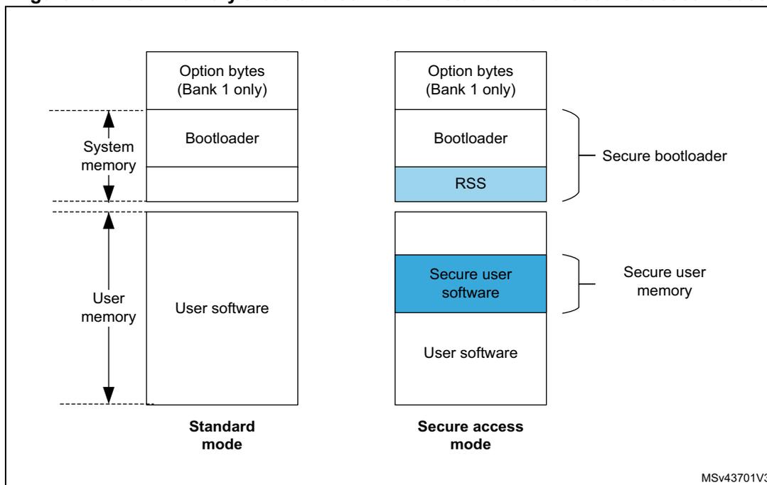
- 1. The protected areas that can only be accessed in Secure access mode are shown in blue.
- 2. A single secure user area can be defined for each bank.
5.3.1 Associated features
The Secure access mode can be configured through option bytes. When it is set, it enables access to:
- • STMicroelectronics root secure services to set secure user areas (see Section 5.4: Root secure services (RSS) )
- • Secure user memory which embeds secure user code and data.
This mode is only defined for the Cortex-M7 core. Cortex-M4 has no access to the option bytes involved in secure memory settings and cannot access these areas. For a summary of access rights for each core, refer to Section 5.6: Summary of flash protection mechanisms .
5.3.2 Boot state machine
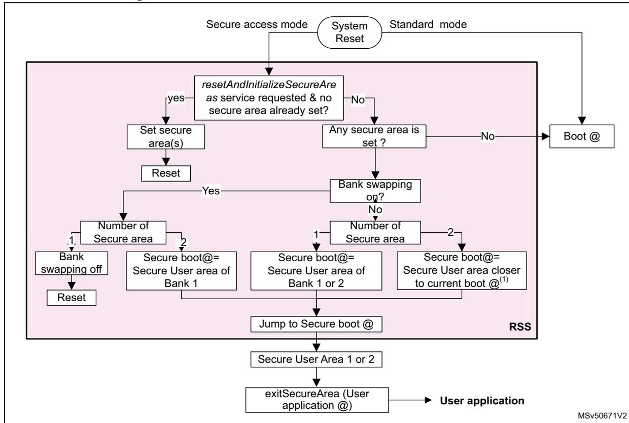
In Secure access mode, booting is forced in the RSS whatever the boot configuration (boot pins and boot addresses). The RSS can either set a secure user memory area if one has been requested (see Section 5.5.2: Setting secure user memory areas ) or jump directly to the existing secure user memory. The code located in secure user memory is executed before the main user application and the bootloader. If no service is required and no secure area is defined, the RSS jumps to the boot address selected by BOOT0 pin value.
Figure 16 shows the boot state machine.
Figure 16. Bootloader state machine in Secure access mode
graph TD
    SR[System Reset] -- Secure access mode --> Q1{resetAndInitializeSecureAre
as service requested & no
secure area already set?}
    SR -- Standard mode --> Boot[Boot @]
    Q1 -- yes --> Set[Set secure area(s)]
    Set --> Reset[Reset]
    Q1 -- No --> Q2{Any secure area is
set?}
    Q2 -- No --> Boot
    Q2 -- Yes --> Q3{Bank swapping
on?}
    Q3 -- Yes --> Num1{Number of
Secure area}
    Num1 -- 1 --> Off[Bank
swapping off]
    Off --> Reset
    Num1 -- 2 --> Boot1[Secure boot@=
Secure User area of
Bank 1]
    Q3 -- No --> Num2{Number of
Secure area}
    Num2 -- 1 --> Boot2[Secure boot@=
Secure User area of
Bank 1 or 2]
    Num2 -- 2 --> Boot3[Secure boot@=
Secure User area closer
to current boot @(1)]
    Boot1 --> Jump[Jump to Secure boot @]
    Boot2 --> Jump
    Boot3 --> Jump
    Jump --> Area[Secure User Area 1 or 2]
    Area --> Exit[exitSecureArea (User
application @)]
    Exit --> App[User application]
    subgraph RSS
    end
    MSV50671V2[MSV50671V2]
1. The current boot is defined by boot address in option byte.
5.3.3 Secure access mode configuration
Enabling Secure access mode
There is no restriction on how to activate Secure access mode on the device. It is configured through the SECURITY option bit in FLASH_OPTSR_CUR register (see Section 4.9.8: FLASH option status register (FLASH_OPTSR_CUR) ).
The Secure access mode becomes active after a system reset.
Disabling Secure access mode
Disabling Secure access mode is a more sensitive task as it can only be done if no more protected code exists on the device. As a result, to come back to Standard mode, secure user memories and PCROP/execute-only areas shall be removed before clearing the SECURITY option bit in the FLASH_OPTSR_CUR register.
Protected areas can be removed by performing a flash mass erase (refer to Section 4.3.10: FLASH erase operations for more details on mass erase sequence).
5.4 Root secure services (RSS)
The root secure services (RSS) are STMicroelectronics ROM code stored on the device. They are part of the security features. These firmware services are available in Secure access mode (see Section 4.5.5: Secure access mode ).
Table 29 gives the addresses of the application programming interface (API) described in the following sections.
Table 29. RSS API addresses
| RSS | RSS API address |
|---|---|
| RSS_getVersion | 0x1FF0 9500 |
| RSS_exitSecureArea | 0x1FF0 9514 |
| RSS_resetAndInitializeSecureAreas | 0x1FF0 9518 |
5.4.1 Secure area setting service
STMicroelectronics provides a service to perform the initialization of secure areas. This service can be called only once. It is executed after a system reset in Secure access mode prior to any other software stored in the device.
Caution: RSS software cannot be accessed (read, write, execute and debug) by the Cortex-M4 core whatever the operating mode, and when the STM32H755xl and STM32H757xl operate in Standard mode. The service can be automatically accessed with ST programming tool, STM32CubeProgrammer, or called through a direct call to the resetAndInitializeSecureAreas function defined below.
resetAndInitializeSecureAreas
| Prototype | void resetAndInitializeSecureAreas(RSS_SecureArea_t area) |
| Arguments | Secure user areas start and end addresses. One or two secure user areas can be set. This service sets secure user area boundaries, following the values stored in the option byte registers: |
| Description |
A system reset is triggered after service completion. |
5.4.2 Secure area exiting service
The RSS also provides the exitSecureArea service. This service must be called to jump to user application. It allows closing safely the secure user area to guarantee that its content can no more be accessed.
Contrary to the resetAndInitializeSecureAreas service, it does not trigger any system reset. exitSecureArea function is defined below:
exitSecureArea| Prototype | void exitSecureArea (unsigned int vectors, unsigned int jtagState) |
| Arguments | Address of application vectors where to jump after exit and state of JTAG after exit: RSS_ENABLE_JTAG_AT_EXIT: JTAG enabled after exiting the secure area RSS_KEEP_JTAG_DISABLED_AT_EXIT: JTAG disabled after exiting the secure area |
| Description | This service is used to exit from secure user software and jump to user main application. There is no system reset triggered by this service |
5.5 Secure user software
A secure user software is a trusted piece of code that is executed after device power-on or after a system reset. It allows building secure applications such as:
- • code signature or integrity checking (user secure boot).
- • software license checking
- • secure firmware update
- • secure initialization
5.5.1 Access rules
Only accessible in Secure access mode, the secure user software is stored in the secure memory areas.
Only one user secure area can be configured per bank. If two secure areas are defined, the secure software that is executed is the one closer to current boot address.
After secure user software execution, the code shall jump to the main user application and prevent access to the secure user area. This is done by calling exitSecureAreas secure service with the application code address given as parameter.
Once in the application code, any access to the secure user area triggers a flash error.
5.5.2 Setting secure user memory areas
One secure area of configurable size can be set in each bank. The size of each area can be set from 512 bytes to full bank with a granularity of 256 bytes:
- • Secure area in bank 1
Boundaries are configured through SEC_AREA_START1 and SEC_AREA_END1 option bits in FLASH_SCAR_CUR1 (see Section 4.9.13: FLASH secure address for bank 1 (FLASH_SCAR_CUR1) ). - • Secure area in bank 2
Boundaries are configured through SEC_AREA_START2 and SEC_AREA_END2 option bits in FLASH_SCAR_CUR2 (see Section 4.9.32: FLASH secure address for bank 2 (FLASH_SCAR_CUR2) ).
Note: If the secure area start address is equal to the secure area end address, the whole bank is considered as secure protected.
The above option bits can only be initialized through resetAndInitializeSecureAreas service.
If a secure area already exists, the secure user area code can update its own secure user area size or create a new one in the other bank.
5.6 Summary of flash protection mechanisms
Figure 17 and Table 30 summarize the access rights of the different flash memory areas for each core, both in Secure access and Standard modes.
Figure 17. Core access to flash memory areas
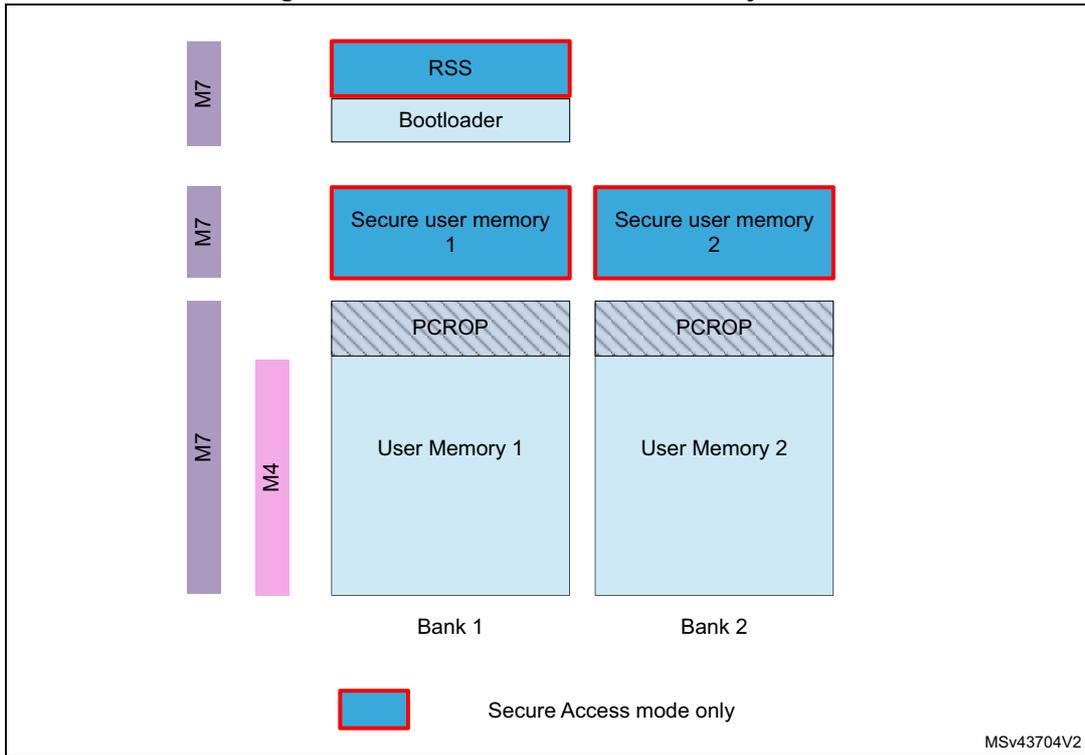
The diagram illustrates the memory layout and access rights for two banks of flash memory. On the left, vertical bars indicate the cores with access: M7 for the top sections, and M7 and M4 for the bottom sections. Bank 1 contains RSS (Secure Access mode only), Bootloader, Secure user memory 1 (Secure Access mode only), PCROP protection, and User Memory 1. Bank 2 contains Secure user memory 2 (Secure Access mode only), PCROP protection, and User Memory 2. A legend at the bottom shows a blue box with a red border labeled 'Secure Access mode only'.
| Memory Area | Core Access | Mode |
|---|---|---|
| RSS | M7 | Secure Access mode only |
| Bootloader | M7 | Standard |
| Secure user memory 1 | M7 | Secure Access mode only |
| Secure user memory 2 | M7 | Secure Access mode only |
| PCROP (Bank 1) | M7, M4 | Standard |
| PCROP (Bank 2) | M7, M4 | Standard |
| User Memory 1 | M7, M4 | Standard |
| User Memory 2 | M7, M4 | Standard |
Table 30. Summary of flash protected areas access rights
| Access type | Core | Software Area | Security mode | Access |
|---|---|---|---|---|
| Execution | Cortex®-M7 | PCROP | Any | ✓ |
| Secure user software | Secure access | ✓ (1) | ||
| Root secure services | Secure access | ✓ (1) | ||
| Cortex®-M4 | PCROP | Any | No | |
| Secure user software | Secure access | No | ||
| Root secure services | Secure access | No | ||
| Read access | Cortex®-M7 | PCROP | Any | No |
| Secure user software | Secure access | ✓ (1) | ||
| Root secure services | Secure access | ✓ (1) | ||
| Cortex®-M4 | PCROP | Any | No | |
| Secure user software | Any | No | ||
| Root secure services | Any | No | ||
| Debug access | Cortex®-M7 | PCROP | Any | No |
| Secure user software | Secure access | No | ||
| Root secure services | Secure access | No | ||
| Cortex®-M4 | Protected area | Any | No |
1. Access rights granted after reset until code completion only.