4. Firewall (FW)
4.1 Introduction
The Firewall is made to protect a specific part of code or data into the Non-Volatile Memory, and/or to protect the Volatile data into the SRAM1 from the rest of the code executed outside the protected area.
4.2 Firewall main features
- • The code to protect by the Firewall (Code Segment) may be located in:
- – The Flash memory map
- – The SRAM1 memory, if declared as an executable protected area during the Firewall configuration step.
- • The data to protect can be located either
- – in the Flash memory (non-volatile data segment)
- – in the SRAM1 memory (volatile data segment)
The software can access these protected areas once the Firewall is opened. The Firewall can be opened or closed using a mechanism based on “call gate” (Refer to Opening the Firewall ).
The start address of each segment and its respective length must be configured before enabling the Firewall (Refer to Section 4.3.5: Firewall initialization ).
Each illegal access into these protected segments (if the Firewall is enabled) generates a reset which immediately kills the detected intrusion.
Any DMA access to protected segments is forbidden whatever the Firewall state (opened or closed). It is considered as an illegal access and generates a reset.
4.3 Firewall functional description
4.3.1 Firewall AMBA bus snoop
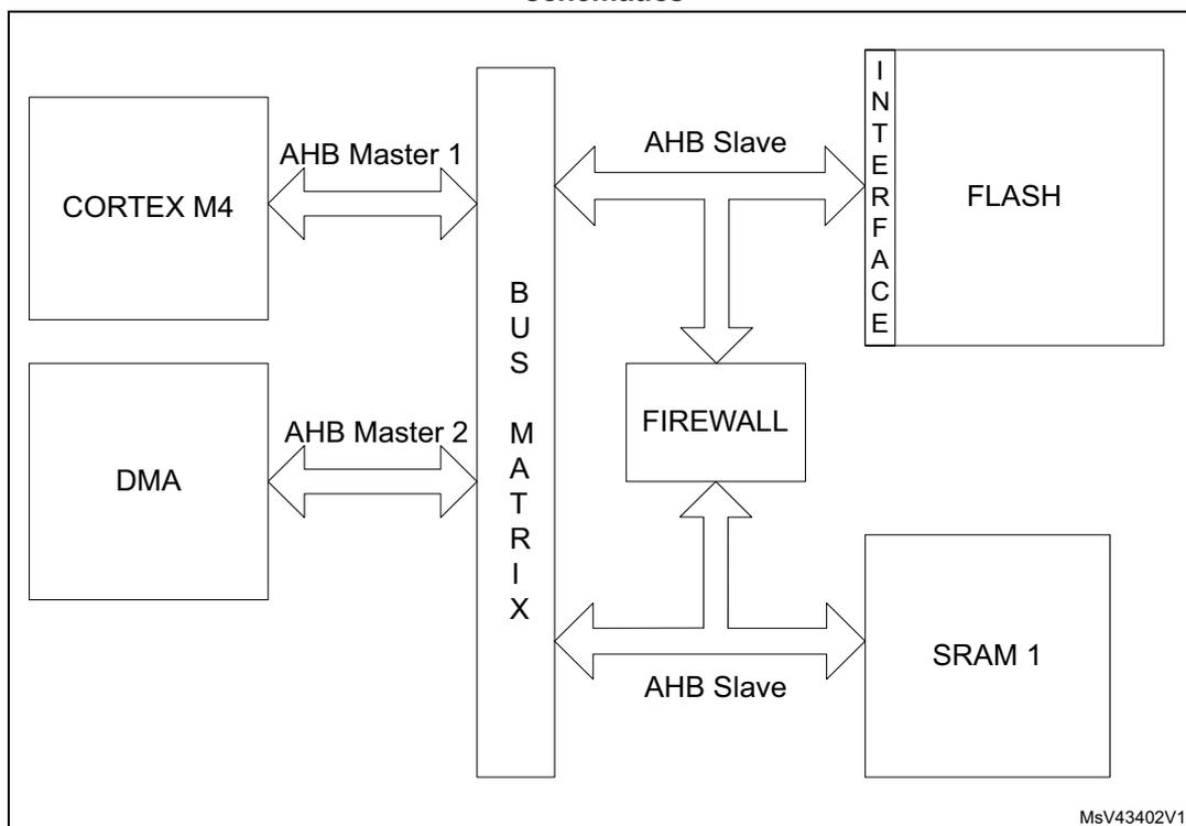
The Firewall peripheral is snooping the AMBA buses on which the memories (volatile and non-volatile) are connected. A global architecture view is illustrated in Figure 5 .
Figure 5. STM32L41xxx/42xxx/43xxx/44xxx/45xxx/46xxx firewall connection schematics
graph LR
    CM4[CORTEX M4] -- "AHB Master 1" --> BM[BUS MATRIX]
    DMA[DMA] -- "AHB Master 2" --> BM
    BM -- "AHB Slave" --> F[FLASH via INTERFACE]
    BM -- "AHB Slave" --> SRAM1[SRAM 1]
    BM --> FW[FIREWALL]
    FW --> BM
4.3.2 Functional requirements
There are several requirements to guarantee the highest security level by the application code/data which needs to be protected by the Firewall and to avoid unwanted Firewall alarm (reset generation).
Debug consideration
In debug mode, if the Firewall is opened, the accesses by the debugger to the protected segments are not blocked. For this reason, the Read out level 2 protection must be active in conjunction with the Firewall implementation.
If the debug is needed, it is possible to proceed in the following way:
- • A dummy code having the same API as the protected code may be developed during the development phase of the final user code. This dummy code may send back coherent answers (in terms of function and potentially timing if needed), as the protected code should do in production phase.
- • In the development phase, the protected code can be given to the customer-end under NDA agreement and its software can be developed in level 0 protection. The customer-
end code needs to embed an IAP located in a write protected segment in order to allow future code updates when the production parts will be Level 2 ROP.
Write protection
In order to offer a maximum security level, the following points need to be respected:
- • It is mandatory to keep a write protection on the part of the code enabling the Firewall. This activation code should be located outside the segments protected by the Firewall.
- • The write protection is also mandatory on the code segment protected by the Firewall.
- • The page including the reset vector must be write-protected.
Interrupts management
The code protected by the Firewall must not be interruptible. It is up to the user code to disable any interrupt source before executing the code protected by the Firewall. If this constraint is not respected, if an interrupt comes while the protected code is executed (Firewall opened), the Firewall will be closed as soon as the interrupt subroutine is executed. When the code returns back to the protected code area, a Firewall alarm will raise since the “call gate” sequence will not be applied and a reset will be generated.
Concerning the interrupt vectors and the first user page in the Flash memory:
- • If the first user page (including the reset vector) is protected by the Firewall, the NVIC vector should be reprogrammed outside the protected segment.
- • If the first user page is not protected by the Firewall, the interrupt vectors may be kept at this location.
There is no interrupt generated by the Firewall.
4.3.3 Firewall segments
The Firewall has been designed to protect three different segment areas:
Code segment
This segment is located into the Flash memory. It should contain the code to execute which requires the Firewall protection. The segment must be reached using the “call gate” entry sequence to open the Firewall. A system reset is generated if the “call gate” entry sequence is not respected (refer to Opening the Firewall ) and if the Firewall is enabled using the FWDIS bit in the system configuration register. The length of the segment and the segment base address must be configured before enabling the Firewall (refer to Section 4.3.5: Firewall initialization ).
Non-volatile data segment
This segment contains non-volatile data used by the protected code which must be protected by the Firewall. The access to this segment is defined into Section 4.3.4: Segment accesses and properties . The Firewall must be opened before accessing the data in this area. The Non-Volatile data segment should be located into the Flash memory. The segment length and the base address of the segment must be configured before enabling the Firewall (refer to Section 4.3.5: Firewall initialization ).
Volatile data segment
Volatile data used by the protected code located into the code segment must be defined into the SRAM1 memory. The access to this segment is defined into the Section 4.3.4: Segment accesses and properties . Depending on the Volatile data segment configuration, the Firewall must be opened or not before accessing this segment area. The segment length and the base address of the segment as well as the segment options must be configured before enabling the Firewall (refer to Section 4.3.5: Firewall initialization ).
The Volatile data segment can also be defined as executable (for the code execution) or shared using two bit of the Firewall configuration register (bit VDS for the volatile data sharing option and bit VDE for the volatile data execution capability). For more details, refer to Table 16 .
4.3.4 Segment accesses and properties
All DMA accesses to the protected segments are forbidden, whatever the Firewall state, and generate a system reset.
Segment access depending on the Firewall state
Each of the three segments has specific properties which are presented in Table 16 .
Table 16. Segment accesses according to the Firewall state
| Segment | Firewall opened access allowed | Firewall closed access allowed | Firewall disabled access allowed |
|---|---|---|---|
| Code segment | Read and execute | No access allowed. Any access to the segment (except the “call gate” entry) generates a system reset | All accesses are allowed (according to the Flash page protection properties in which the code is located) |
| Non-volatile data segment | Read and write | No access allowed | All accesses are allowed (according to the Flash page protection properties in which the code is located) |
| Volatile data segment | Read and Write Execute if VDE = 1 and VDS = 0 into the Firewall configuration register | No access allowed if VDS = 0 and VDE = 0 into the Firewall configuration register Read/write/execute accesses allowed if VDS = 1 (whatever VDE bit value) Execute if VDE = 1 and VDS = 0 but with a “call gate” entry to open the Firewall at first. | All accesses are allowed |
The Volatile data segment is a bit different from the two others. The segment can be:
- • Shared (VDS bit in the register)
It means that the area and the data located into this segment can be shared between the protected code and the user code executed in a non-protected area. The access is allowed whether the Firewall is opened or closed or disabled.
The VDS bit gets priority over the VDE bit, this last bit value being ignored in such a case. It means that the Volatile data segment can execute parts of code located there without any need to open the Firewall before executing the code.
- • Execute
The VDE bit is considered as soon as the VDS bit = 0 in the FW_CR register. If the VDS bit = 1, refer to the description above on the Volatile data segment sharing. If VDS = 0 and VDE = 1, the Volatile data segment is executable. To avoid a system reset generation from the Firewall, the “call gate” sequence should be applied on the Volatile data segment to open the Firewall as an entry point for the code execution.
Segments properties
Each segment has a specific length register to define the segment size to be protected by the Firewall: CSL register for the Code segment length register, NVDSL for the Non-volatile data segment length register, and VDSL register for the Volatile data segment length register. Granularity and area ranges for each of the segments are presented in Table 17 .
Table 17. Segment granularity and area ranges
| Segment | Granularity | Area range |
|---|---|---|
| Code segment | 256 byte | 1024 Kbytes - 256 bytes |
| Non-volatile data segment | 256 byte | 1024 Kbytes - 256 bytes |
| Volatile data segment (1) | 64 byte | 96 Kbytes - 64 bytes |
| Volatile data segment (2) | 64 byte | 128 Kbyte - 64 byte |
1. Applicable to STM32L43xxx and STM32L44xxx devices only.
2. Applicable to STM32L45xxx and STM32L46xxx devices only.
4.3.5 Firewall initialization
The initialization phase should take place at the beginning of the user code execution (refer to the Write protection ).
The initialization phase consists of setting up the addresses and the lengths of each segment which needs to be protected by the Firewall. It must be done before enabling the Firewall, because the enabling bit can be written once. Thus, when the Firewall is enabled, it cannot be disabled anymore until the next system reset.
Once the Firewall is enabled, the accesses to the address and length segments are no longer possible. All write attempts are discarded.
A segment defined with a length equal to 0 is not considered as protected by the Firewall. As a consequence, there is no reset generation from the Firewall when an access to the base address of this segment is performed.
After a reset, the Firewall is disabled by default (FWDIS bit in the SYSCFG register is set). It has to be cleared to enable the Firewall feature.
Below is the initialization procedure to follow:
- 1. Configure the RCC to enable the clock to the Firewall module
- 2. Configure the RCC to enable the clock of the system configuration registers
- 3. Set the base address and length of each segment (CSSA, CSL, NVDSSA, NVDSL, VDSSA, VDSL registers)
- 4. Set the configuration register of the Firewall (FW_CR register)
- 5. Enable the Firewall clearing the FWDIS bit in the system configuration register.
The Firewall configuration register (FW_CR register) is the only one which can be managed in a dynamic way even if the Firewall is enabled:
- • when the Non-Volatile data segment is undefined (meaning the NVDSL register is equal to 0), the accesses to this register are possible whatever the Firewall state (opened or closed).
- • when the Non-Volatile data segment is defined (meaning the NVDSL register is different from 0), the accesses to this register are only possible when the Firewall is opened.
4.3.6 Firewall states
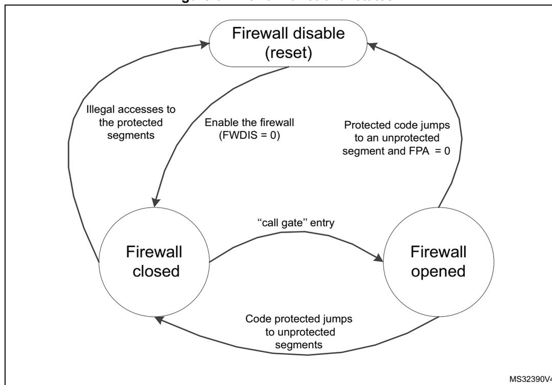
The Firewall has three different states as shown in Figure 6 :
- • Disabled: The FWDIS bit is set by default after the reset. The Firewall is not active.
- • Closed: The Firewall protects the accesses to the three segments (Code, Non-volatile data, and Volatile data segments).
- • Opened: The Firewall allows access to the protected segments as defined in Section 4.3.4: Segment accesses and properties .
Figure 6. Firewall functional states
graph TD;
    A((Firewall disable (reset))) -- "Illegal accesses to the protected segments" --> B((Firewall closed));
    A -- "Enable the firewall (FWDIS = 0)" --> B;
    B -- ""call gate" entry" --> C((Firewall opened));
    C -- "Protected code jumps to an unprotected segment and FPA = 0" --> A;
    C -- "Code protected jumps to unprotected segments" --> B;
The diagram shows three states of the Firewall: 'Firewall disable (reset)' at the top, 'Firewall closed' at the bottom left, and 'Firewall opened' at the bottom right. Transitions are as follows: from 'Firewall disable (reset)' to 'Firewall closed' via 'Enable the firewall (FWDIS = 0)'; from 'Firewall closed' to 'Firewall disable (reset)' via 'Illegal accesses to the protected segments'; from 'Firewall closed' to 'Firewall opened' via '"call gate" entry'; from 'Firewall opened' to 'Firewall disable (reset)' via 'Protected code jumps to an unprotected segment and FPA = 0'; and from 'Firewall opened' to 'Firewall closed' via 'Code protected jumps to unprotected segments'.
MS32390V4
Opening the Firewall
As soon as the Firewall is enabled, it is closed. It means that most of the accesses to the protected segments are forbidden (refer to Section 4.3.4: Segment accesses and properties ). In order to open the Firewall to interact with the protected segments, it is mandatory to apply the “call gate” sequence described hereafter.
“call gate” sequence
The “call gate” is composed of 3 words located on the first three 32-bit addresses of the base address of the code segment and of the Volatile data segment if it is declared as not shared (VDS = 0) and executable (VDE = 1).
- – 1st word: Dummy 32-bit words always closed in order to protect the “call gate” opening from an access due to a prefetch buffer.
- – 2nd and 3rd words: 2 specific 32-bit words called “call gate” and always opened.
To open the Firewall, the code currently executed must jump to the 2 nd word of the “call gate” and execute the code from this point. The 2nd word and 3rd word execution must not be interrupted by any intermediate instruction fetch; otherwise, the Firewall is not considered open and comes back to a close state. Then, executing the 3 rd word after receiving the intermediate instruction fetch would generate a system reset as a consequence.
As soon as the Firewall is opened, the protected segments can be accessed as described in Section 4.3.4: Segment accesses and properties .
Closing the Firewall
The Firewall is closed immediately after it is enabled (clearing the FWDIS bit in the system configuration register).
To close the Firewall, the protected code must:
- • Write the correct value in the Firewall Pre Arm Flag into the FW_CR register.
- • Jump to any executable location outside the Firewall segments.
If the Firewall Pre Arm Flag is not set when the protected code jumps to a non protected segment, a reset is generated. This control bit is an additional protection to avoid an undesired attempt to close the Firewall with the private information not yet cleaned (see the note below).
For security reasons, following the application for which the Firewall is used, it is advised to clean all private information from CPU registers and hardware cells.
4.4 Firewall registers
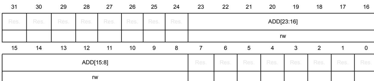
4.4.1 Code segment start address (FW_CSSA)
Address offset: 0x00
Reset value: 0x0000 0000
| 31 | 30 | 29 | 28 | 27 | 26 | 25 | 24 | 23 | 22 | 21 | 20 | 19 | 18 | 17 | 16 |
|---|---|---|---|---|---|---|---|---|---|---|---|---|---|---|---|
| Res. | Res. | Res. | Res. | Res. | Res. | Res. | Res. | ADD[23:16] | |||||||
| rw | |||||||||||||||
| 15 | 14 | 13 | 12 | 11 | 10 | 9 | 8 | 7 | 6 | 5 | 4 | 3 | 2 | 1 | 0 |
|---|---|---|---|---|---|---|---|---|---|---|---|---|---|---|---|
| ADD[15:8] | Res. | Res. | Res. | Res. | Res. | Res. | Res. | Res. | |||||||
| rw | |||||||||||||||
Bits 31:24 Reserved, must be kept at reset value.
Bits 23:8 ADD[23:8] : code segment start address
The LSB bits of the start address (bit 7:0) are reserved and forced to 0 in order to allow a 256-byte granularity.
Note: These bits can be written only before enabling the Firewall. Refer to Section 4.3.5: Firewall initialization .
Bits 7:0 Reserved, must be kept at the reset value.
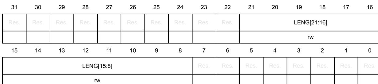
4.4.2 Code segment length (FW_CSL)
Address offset: 0x04
Reset value: 0x0000 0000
| 31 | 30 | 29 | 28 | 27 | 26 | 25 | 24 | 23 | 22 | 21 | 20 | 19 | 18 | 17 | 16 |
|---|---|---|---|---|---|---|---|---|---|---|---|---|---|---|---|
| Res. | Res. | Res. | Res. | Res. | Res. | Res. | Res. | Res. | Res. | LENG[21:16] | |||||
| rw | |||||||||||||||
| 15 | 14 | 13 | 12 | 11 | 10 | 9 | 8 | 7 | 6 | 5 | 4 | 3 | 2 | 1 | 0 |
|---|---|---|---|---|---|---|---|---|---|---|---|---|---|---|---|
| LENG[15:8] | Res. | Res. | Res. | Res. | Res. | Res. | Res. | Res. | |||||||
| rw | |||||||||||||||
Bits 31:22 Reserved, must be kept at the reset value.
Bits 21:8 LENG[21:8] : code segment length
LENG[21:8] selects the size of the code segment expressed in bytes but is a multiple of 256 bytes.
The segment area is defined from {ADD[23:8], 0x00} to {ADD[23:8]+LENG[21:8], 0x00} - 0x01
Note: If LENG[21:8] = 0 after enabling the Firewall, this segment is not defined, thus not protected by the Firewall.
These bits can only be written before enabling the Firewall. Refer to Section 4.3.5: Firewall initialization .
Bits 7:0 Reserved, must be kept at the reset value.
4.4.3 Non-volatile data segment start address (FW_NVDSSA)
Address offset: 0x08
Reset value: 0x0000 0000
| 31 | 30 | 29 | 28 | 27 | 26 | 25 | 24 | 23 | 22 | 21 | 20 | 19 | 18 | 17 | 16 |
|---|---|---|---|---|---|---|---|---|---|---|---|---|---|---|---|
| Res. | Res. | Res. | Res. | Res. | Res. | Res. | Res. | ADD[23:16] | |||||||
| rw | |||||||||||||||
| 15 | 14 | 13 | 12 | 11 | 10 | 9 | 8 | 7 | 6 | 5 | 4 | 3 | 2 | 1 | 0 |
|---|---|---|---|---|---|---|---|---|---|---|---|---|---|---|---|
| ADD[15:8] | Res. | Res. | Res. | Res. | Res. | Res. | Res. | Res. | |||||||
| rw | |||||||||||||||
Bits 31:24 Reserved, must be kept at the reset value.
Bits 23:8 ADD[23:8] : Non-volatile data segment start address
The LSB bits of the start address (bit 7:0) are reserved and forced to 0 in order to allow a 256-byte granularity.
Note: These bits can only be written before enabling the Firewall. Refer to Section 4.3.5: Firewall initialization .
Bits 7:0 Reserved, must be kept at the reset value.
4.4.4 Non-volatile data segment length (FW_NVDL)
Address offset: 0x0C
Reset value: 0x0000 0000
| 31 | 30 | 29 | 28 | 27 | 26 | 25 | 24 | 23 | 22 | 21 | 20 | 19 | 18 | 17 | 16 |
|---|---|---|---|---|---|---|---|---|---|---|---|---|---|---|---|
| Res. | Res. | Res. | Res. | Res. | Res. | Res. | Res. | Res. | Res. | LENG[21:16] | |||||
| rw | |||||||||||||||
| 15 | 14 | 13 | 12 | 11 | 10 | 9 | 8 | 7 | 6 | 5 | 4 | 3 | 2 | 1 | 0 |
|---|---|---|---|---|---|---|---|---|---|---|---|---|---|---|---|
| LENG[15:8] | Res. | Res. | Res. | Res. | Res. | Res. | Res. | Res. | |||||||
| rw | |||||||||||||||
Bits 31:22 Reserved, must be kept at the reset value.
Bits 21:8 LENG[21:8] : Non-volatile data segment length
LENG[21:8] selects the size of the Non-volatile data segment expressed in bytes but is a multiple of 256 bytes.
The segment area is defined from {ADD[23:8], 0x00} to {ADD[23:8]+LENG[21:8], 0x00} - 0x01
Note: If LENG[21:8] = 0 after enabling the Firewall, this segment is not defined, thus not protected by the Firewall.
These bits can only be written before enabling the Firewall. Refer to Section 4.3.5: Firewall initialization .
Bits 7:0 Reserved, must be kept at the reset value.
4.4.5 Volatile data segment start address (FW_VDSSA)
Address offset: 0x10
Reset value: 0x0000 0000
| 31 | 30 | 29 | 28 | 27 | 26 | 25 | 24 | 23 | 22 | 21 | 20 | 19 | 18 | 17 | 16 |
|---|---|---|---|---|---|---|---|---|---|---|---|---|---|---|---|
| Res. | Res. | Res. | Res. | Res. | Res. | Res. | Res. | Res. | Res. | Res. | Res. | Res. | Res. | Res. | ADD [16] |
| rw | |||||||||||||||
| 15 | 14 | 13 | 12 | 11 | 10 | 9 | 8 | 7 | 6 | 5 | 4 | 3 | 2 | 1 | 0 |
| ADD[15:6] | Res. | Res. | Res. | Res. | Res. | Res. | |||||||||
| rw | |||||||||||||||
Bits 31:17 Reserved, must be kept at the reset value.
Bits 16:6 ADD[16:6] : Volatile data segment start address
The LSB bits of the start address (bit 5:0) are reserved and forced to 0 in order to allow a 64-byte granularity.
Note: These bits can only be written before enabling the Firewall. Refer to Section 4.3.5: Firewall initialization
Bits 5:0 Reserved, must be kept at the reset value.
4.4.6 Volatile data segment length (FW_VDSL)
Address offset: 0x14
Reset value: 0x0000 0000
| 31 | 30 | 29 | 28 | 27 | 26 | 25 | 24 | 23 | 22 | 21 | 20 | 19 | 18 | 17 | 16 |
|---|---|---|---|---|---|---|---|---|---|---|---|---|---|---|---|
| Res. | Res. | Res. | Res. | Res. | Res. | Res. | Res. | Res. | Res. | Res. | Res. | Res. | Res. | Res. | LENG [16] |
| rw | |||||||||||||||
| 15 | 14 | 13 | 12 | 11 | 10 | 9 | 8 | 7 | 6 | 5 | 4 | 3 | 2 | 1 | 0 |
| LENG[15:6] | Res. | Res. | Res. | Res. | Res. | Res. | |||||||||
| rw | |||||||||||||||
Bits 31:17 Reserved, must be kept at the reset value.
Bits 16:6 LENG[16:6] : volatile data segment length
LENG[16:6] selects the size of the volatile data segment expressed in bytes but is a multiple of 64 bytes.
The segment area is defined from {ADD[16:6],0x00} to {ADD[16:6]+LENG[16:6], 0x00} - 0x01
Note: If LENG[16:6] = 0 after enabling the Firewall, this segment is not defined, thus not protected by the Firewall.
These bits can only be written before enabling the Firewall. Refer to Section 4.3.5: Firewall initialization .
Bits 5:0 Reserved, must be kept at the reset value.
4.4.7 Configuration register (FW_CR)
Address offset: 0x20
Reset value: 0x0000 0000
| 31 | 30 | 29 | 28 | 27 | 26 | 25 | 24 | 23 | 22 | 21 | 20 | 19 | 18 | 17 | 16 |
|---|---|---|---|---|---|---|---|---|---|---|---|---|---|---|---|
| Res. | Res. | Res. | Res. | Res. | Res. | Res. | Res. | Res. | Res. | Res. | Res. | Res. | Res. | Res. | Res. |
| 15 | 14 | 13 | 12 | 11 | 10 | 9 | 8 | 7 | 6 | 5 | 4 | 3 | 2 | 1 | 0 |
| Res. | Res. | Res. | Res. | Res. | Res. | Res. | Res. | Res. | Res. | Res. | Res. | Res. | VDE | VDS | FPA |
| rw | rw | rw |
Bits 31:3 Reserved, must be kept at the reset value.
Bit 2 VDE: Volatile data execution
0: Volatile data segment cannot be executed if VDS = 0
1: Volatile data segment is declared executable whatever VDS bit value
When VDS = 1, this bit has no meaning. The Volatile data segment can be executed whatever the VDE bit value.
If VDS = 1, the code can be executed whatever the Firewall state (opened or closed)
If VDS = 0, the code can only be executed if the Firewall is opened or applying the “call gate” entry sequence if the Firewall is closed.
Refer to Segment access depending on the Firewall state .
Bit 1 VDS: Volatile data shared
0: Volatile data segment is not shared and cannot be hit by a non protected executable code when the Firewall is closed. If it is accessed in such a condition, a system reset will be generated by the Firewall.
1: Volatile data segment is shared with non protected application code. It can be accessed whatever the Firewall state (opened or closed).
Refer to Segment access depending on the Firewall state .
Bit 0 FPA: Firewall prearm
0: any code executed outside the protected segment when the Firewall is opened will generate a system reset.
1: any code executed outside the protected segment will close the Firewall.
Refer to Closing the Firewall .
This register is protected in the same way as the Non-volatile data segment (refer to Section 4.3.5: Firewall initialization ).
4.4.8 Firewall register map
The table below provides the Firewall register map and reset values.
Table 18. Firewall register map and reset values
| Offset | Register | 31 | 30 | 29 | 28 | 27 | 26 | 25 | 24 | 23 | 22 | 21 | 20 | 19 | 18 | 17 | 16 | 15 | 14 | 13 | 12 | 11 | 10 | 9 | 8 | 7 | 6 | 5 | 4 | 3 | 2 | 1 | 0 |
|---|---|---|---|---|---|---|---|---|---|---|---|---|---|---|---|---|---|---|---|---|---|---|---|---|---|---|---|---|---|---|---|---|---|
| 0x0 | FW_CSSA | Res. | Res. | Res. | Res. | Res. | Res. | Res. | Res. | ADD | Res. | Res. | Res. | Res. | Res. | Res. | Res. | Res. | |||||||||||||||
| Reset Value | 0 | 0 | 0 | 0 | 0 | 0 | 0 | 0 | 0 | 0 | 0 | 0 | 0 | 0 | 0 | 0 | |||||||||||||||||
| 0x4 | FW_CSL | Res. | Res. | Res. | Res. | Res. | Res. | Res. | Res. | Res. | LENG | Res. | Res. | Res. | Res. | Res. | Res. | Res. | Res. | ||||||||||||||
| Reset Value | 0 | 0 | 0 | 0 | 0 | 0 | 0 | 0 | 0 | 0 | 0 | 0 | 0 | 0 | |||||||||||||||||||
| 0x8 | FW_NVDSSA | Res. | Res. | Res. | Res. | Res. | Res. | Res. | Res. | ADD | Res. | Res. | Res. | Res. | Res. | Res. | Res. | Res. | |||||||||||||||
| Reset Value | 0 | 0 | 0 | 0 | 0 | 0 | 0 | 0 | 0 | 0 | 0 | 0 | 0 | 0 | 0 | 0 | |||||||||||||||||
| 0xC | FW_NVDLS | Res. | Res. | Res. | Res. | Res. | Res. | Res. | Res. | Res. | LENG | Res. | Res. | Res. | Res. | Res. | Res. | Res. | Res. | ||||||||||||||
| Reset Value | 0 | 0 | 0 | 0 | 0 | 0 | 0 | 0 | 0 | 0 | 0 | 0 | 0 | 0 | |||||||||||||||||||
| 0x10 | FW_VDSSA | Res. | Res. | Res. | Res. | Res. | Res. | Res. | Res. | Res. | Res. | Res. | Res. | Res. | Res. | Res. | ADD | Res. | Res. | Res. | |||||||||||||
| Reset Value | 0 | 0 | 0 | 0 | 0 | 0 | 0 | 0 | 0 | 0 | 0 | 0 | 0 | 0 | 0 | ||||||||||||||||||
| 0x14 | FW_VDSL | Res. | Res. | Res. | Res. | Res. | Res. | Res. | Res. | Res. | Res. | Res. | Res. | Res. | Res. | Res. | LENG | Res. | Res. | Res. | |||||||||||||
| Reset Value | 0 | 0 | 0 | 0 | 0 | 0 | 0 | 0 | 0 | 0 | 0 | 0 | 0 | 0 | 0 | ||||||||||||||||||
| 0x18 | Res. | Res. | Res. | Res. | Res. | Res. | Res. | Res. | Res. | Res. | Res. | Res. | Res. | Res. | Res. | Res. | Res. | Res. | Res. | Res. | Res. | Res. | Res. | Res. | Res. | Res. | Res. | Res. | Res. | Res. | Res. | ||
| Reset Value | |||||||||||||||||||||||||||||||||
| 0x1C | Res. | Res. | Res. | Res. | Res. | Res. | Res. | Res. | Res. | Res. | Res. | Res. | Res. | Res. | Res. | Res. | Res. | Res. | Res. | Res. | Res. | Res. | Res. | Res. | Res. | Res. | Res. | Res. | Res. | Res. | Res. | ||
| Reset Value | |||||||||||||||||||||||||||||||||
| 0x20 | FW_CR | Res. | Res. | Res. | Res. | Res. | Res. | Res. | Res. | Res. | Res. | Res. | Res. | Res. | Res. | Res. | Res. | Res. | Res. | Res. | Res. | Res. | Res. | Res. | Res. | Res. | Res. | Res. | Res. | Res. | VDE | VDS | FPA |
| Reset Value | 0 | 0 | 0 | ||||||||||||||||||||||||||||||
Refer to Section 2.2 on page 70 for the register boundary addresses.