12. Extended interrupt and event controller (EXTI)
12.1 Introduction
The extended interrupts and events controller (EXTI) manages the external and internal asynchronous events/interrupts and generates the event request to the CPU/interrupt controller plus a wake-up request to the power controller.
The EXTI allows the management of up to 30 event lines which can wake up the device from Stop mode.
Some of the lines are configurable: in this case the active edge can be chosen independently, and a status flag indicates the source of the interrupt. The configurable lines are used by the I/Os external interrupts, and by few peripherals. Some of the lines are direct: they are used by some peripherals to generate a wakeup from Stop event or interrupt. In this case the status flag is provided by the peripheral.
Each line can be masked independently for interrupt or event generation.
The EXTI controller also allows to emulate, by programming to a dedicated register, events or interrupts by software multiplexed with the corresponding hardware event line.
12.2 EXTI main features
The EXTI main features are the following:
- • Generation of up to 30 event/interrupt requests (configurable and direct lines).
- • Independent mask on each event/interrupt line
- • Configurable rising or falling edge (configurable lines only)
- • Dedicated status bit (configurable lines only)
- • Emulation of event/interrupt requests (configurable lines only)
12.3 EXTI functional description
For the configurable interrupt lines, the interrupt line should be configured and enabled in order to generate an interrupt. This is done by programming the two trigger registers with the desired edge detection and by enabling the interrupt request by writing a '1' to the corresponding bit in the interrupt mask register. When the selected edge occurs on the interrupt line, an interrupt request is generated. The pending bit corresponding to the interrupt line is also set. This request is cleared by writing a '1' in the pending register.
For the direct interrupt lines: the interrupt is enabled by default in the interrupt mask register and there is no corresponding pending bit in the pending register.
To generate an event, the event line should be configured and enabled. This is done by programming the two trigger registers with the desired edge detection and by enabling the event request by writing a '1' to the corresponding bit in the event mask register. When the selected edge occurs on the event line, an event pulse is generated. The pending bit corresponding to the event line is not set.
For the configurable lines, an interrupt/event request can also be generated by software by writing a '1' in the software interrupt/event register.
Note: The interrupts or events associated to the direct lines are triggered only when the system is in Stop mode. If the system is still running, no interrupt/event is generated by the EXTI.
12.3.1 EXTI block diagram
The block diagram is shown in Figure 27 .
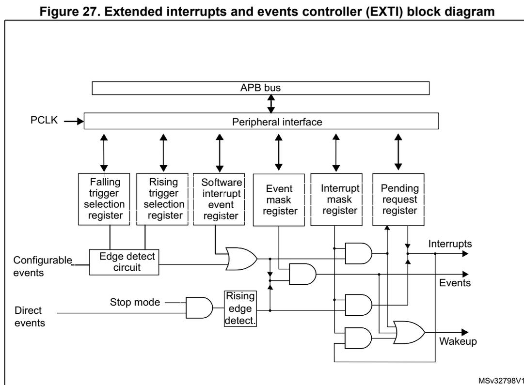
Figure 27. Extended interrupts and events controller (EXTI) block diagram
The diagram illustrates the internal architecture of the EXTI. At the top, an
APB bus
is connected via a bidirectional arrow to a
Peripheral interface
, which also receives a
PCLK
clock signal. Below the interface, six registers are shown with bidirectional arrows to the interface:
Falling trigger selection register
,
Rising trigger selection register
,
Software interrupt event register
,
Event mask register
,
Interrupt mask register
, and
Pending request register
.
The logic flow is as follows:
1.
Configurable events
enter an
Edge detect circuit
, which is controlled by the Falling and Rising trigger selection registers.
2. The output of the edge detect circuit, along with the Software interrupt event register, goes into an OR gate.
3. The output of this OR gate splits: one path goes to an AND gate with the Interrupt mask register to set the
Pending request register
, which then outputs
Interrupts
. Another path goes to an AND gate with the Event mask register to output
Events
.
4.
Direct events
enter an AND gate with a
Stop mode
signal. The output goes to a
Rising edge detect.
block.
5. The output of the Rising edge detect block is combined via OR gates with the outputs of the mask-controlled AND gates to produce a
Wakeup
signal.
The identifier
MSv32798V1
is in the bottom right corner.
12.3.2 Wakeup event management
The STM32L0x1 microcontrollers are able to handle external or internal events in order to wake up the core (WFE). The wakeup event can be generated by either:
- • enabling an interrupt in the peripheral control register but not in the NVIC, and enabling the SEVONPEND bit in the Cortex ® -M0+ system control register (see STM32L0 Series Cortex ® -M0+ programming manual (PM0223)). When the MCU resumes from WFE, the peripheral interrupt pending bit and the peripheral NVIC IRQ channel pending bit (in the NVIC interrupt clear pending register) have to be cleared.
- • or configuring an EXTI line in event mode. When the CPU resumes from WFE, it is not necessary to clear the peripheral interrupt pending bit or the NVIC IRQ channel pending bit as the pending bit corresponding to the event line is not set.
12.3.3 Peripherals asynchronous interrupts
Some peripherals can generate events when the system is in Run mode or in Stop mode, thus allowing to wake up the system from Stop mode.
To accomplish this, the peripheral generates both a synchronized (to the system clock, e.g. APB clock) and an asynchronous version of the event. This asynchronous event is connected to an EXTI direct line.
Note: Few peripherals with wakeup from Stop capability are connected to an EXTI configurable line. In this case the EXTI configuration is required to allow the wakeup from Stop mode.
12.3.4 Hardware interrupt selection
To configure a line as an interrupt source, use the following procedure:
- 1. Configure the mask bits of the Interrupt lines (EXTI_IMR)
- 2. Configure the Trigger Selection bits of the Interrupt lines (EXTI_RTSR and EXTI_FTSR)
- 3. Configure the enable and mask bits that control the NVIC IRQ channel mapped to the extended interrupt controller (EXTI) so that an interrupt coming from any one of the lines can be correctly acknowledged.
The direct lines do not require any EXTI configuration.
For code example, refer to A.7.2: Extended interrupt selection code example .
12.3.5 Hardware event selection
To configure a line as an event source, use the following procedure:
- 1. Configure the mask bits of the Event lines (EXTI_EMR)
- 2. Configure the Trigger Selection bits of the Event lines (EXTI_RTSR and EXTI_FTSR).
12.3.6 Software interrupt/event selection
Any of the configurable lines can be configured as software interrupt/event lines. The procedure below must be followed to generate a software interrupt.
- 1. Configure the mask bits of the Interrupt/Event lines (EXTI_IMR, EXTI_EMR)
- 2. Set the required bit in the software interrupt register (EXTI_SWIER).
12.4 EXTI interrupt/event line mapping
In the STM32L0x1, 30 interrupt/event lines are available. The GPIOs are connected to 16 configurable interrupt/event lines as shown in Figure 28 .
Figure 28. Extended interrupt/event GPIO mapping
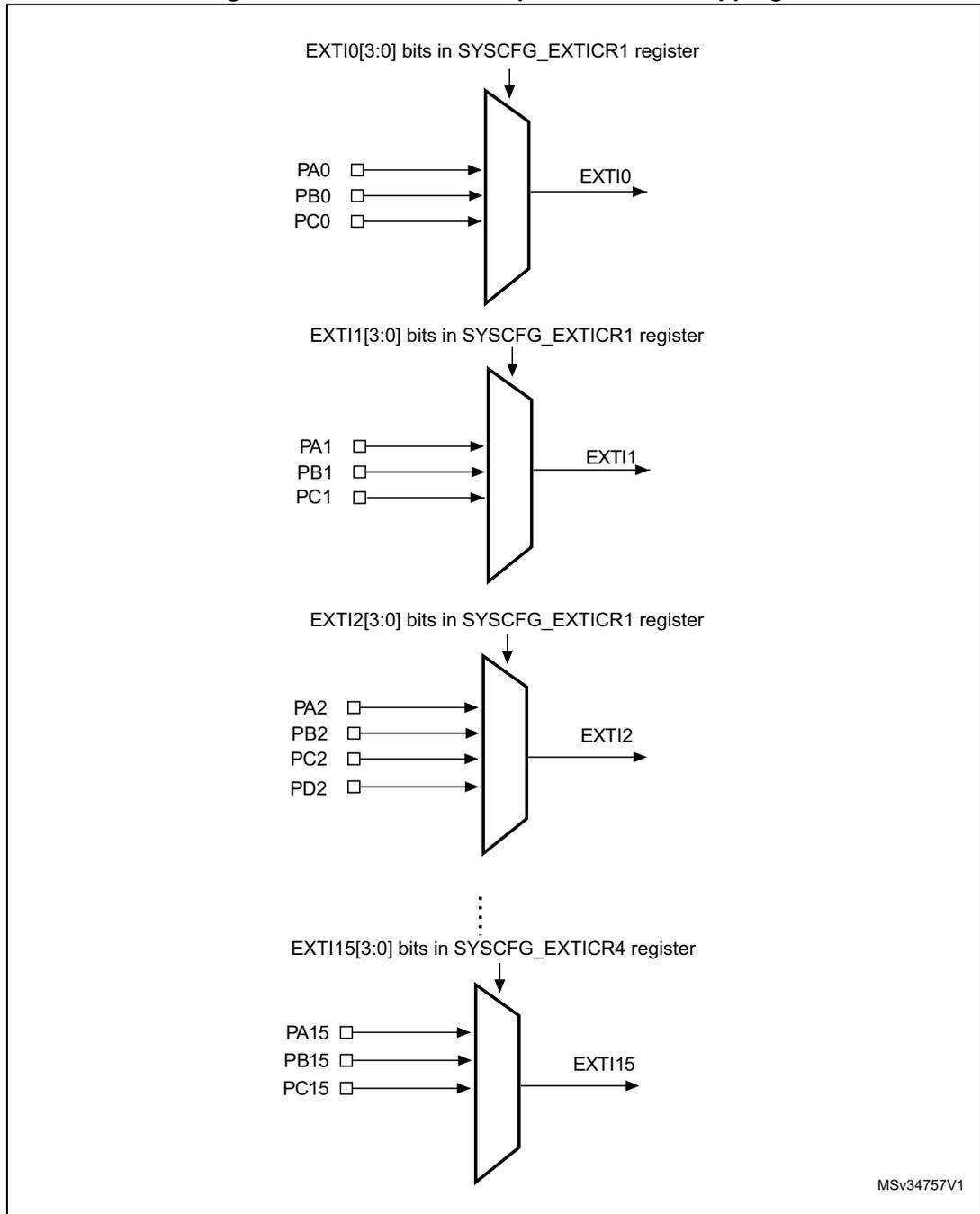
The diagram illustrates the mapping of GPIO pins to EXTI interrupt lines. It shows four specific examples, with vertical ellipses indicating the continuation of the pattern for the remaining lines.
- EXTI0: Controlled by EXTI0[3:0] bits in the SYSCFG_EXTICR1 register. Inputs: PA0, PB0, PC0. Output: EXTI0.
- EXTI1: Controlled by EXTI1[3:0] bits in the SYSCFG_EXTICR1 register. Inputs: PA1, PB1, PC1. Output: EXTI1.
- EXTI2: Controlled by EXTI2[3:0] bits in the SYSCFG_EXTICR1 register. Inputs: PA2, PB2, PC2, PD2. Output: EXTI2.
- EXTI15: Controlled by EXTI15[3:0] bits in the SYSCFG_EXTICR4 register. Inputs: PA15, PB15, PC15. Output: EXTI15.
MSV34757V1
Note: Refer to the datasheet for the list of available I/O ports.
The 30 lines are connected as shown in Table 54: EXTI lines connections :
Table 54. EXTI lines connections| EXTI line | Line source | Line type |
|---|---|---|
| 0-15 | GPIO | configurable |
| 16 | PVD | configurable |
| 17 | RTC alarm | configurable |
| 18 | Reserved | |
| 19 | RTC tamper or timestamp or CSS_LSE | configurable |
| 20 | RTC wakeup timer | configurable |
| 21 | COMP1 output | configurable |
| 22 | COMP2 output | configurable |
| 23 | I2C1 wakeup | direct |
| 24 | I2C3 wakeup | direct |
| 25 | USART 1 wakeup | direct |
| 26 | USART2 wakeup | direct |
| 27 | Reserved | |
| 28 | LPUART1 wakeup | direct |
| 29 | LPTIM1 wakeup | direct |
12.5 EXTI registers
Refer to Section 1.2 for a list of abbreviations used in register descriptions.
The peripheral registers have to be accessed by words (32-bit).
12.5.1 EXTI interrupt mask register (EXTI_IMR)
Address offset: 0x00
Reset value: 0x3F84 0000
| 31 | 30 | 29 | 28 | 27 | 26 | 25 | 24 | 23 | 22 | 21 | 20 | 19 | 18 | 17 | 16 |
|---|---|---|---|---|---|---|---|---|---|---|---|---|---|---|---|
| Res. | Res. | IM29 | IM28 | Res. | IM26 | IM25 | IM24 | IM23 | IM22 | IM21 | IM20 | IM19 | Res. | IM17 | IM16 |
| rw | rw | rw | rw | rw | rw | rw | rw | rw | rw | rw | rw | ||||
| 15 | 14 | 13 | 12 | 11 | 10 | 9 | 8 | 7 | 6 | 5 | 4 | 3 | 2 | 1 | 0 |
| IM15 | IM14 | IM13 | IM12 | IM11 | IM10 | IM9 | IM8 | IM7 | IM6 | IM5 | IM4 | IM3 | IM2 | IM1 | IM0 |
| rw | rw | rw | rw | rw | rw | rw | rw | rw | rw | rw | rw | rw | rw | rw | rw |
Bits 31:30 Reserved, must be kept at reset value.
Bits 29:28
IMx
: Interrupt mask on line x (x = 29 to 28)
0: Interrupt request from Line x is masked
1: Interrupt request from Line x is not masked
Bit 27 Reserved, must be kept at reset value.
Bits 26:19
IMx
: Interrupt mask on line x (x = 26 to 19)
0: Interrupt request from Line x is masked
1: Interrupt request from Line x is not masked
Bit 18 Reserved, must be kept at reset value.
Bits 17:0
IMx
: Interrupt mask on line x (x = 17 to 0)
0: Interrupt request from Line x is masked
1: Interrupt request from Line x is not masked
12.5.2 EXTI event mask register (EXTI_EMR)
Address offset: 0x04
Reset value: 0x0000 0000
| 31 | 30 | 29 | 28 | 27 | 26 | 25 | 24 | 23 | 22 | 21 | 20 | 19 | 18 | 17 | 16 |
|---|---|---|---|---|---|---|---|---|---|---|---|---|---|---|---|
| Res. | Res. | EM29 | EM28 | Res. | EM26 | EM25 | EM24 | EM23 | EM22 | EM21 | EM20 | EM19 | Res. | EM17 | EM16 |
| rw | rw | rw | rw | rw | rw | rw | rw | rw | rw | rw | rw | ||||
| 15 | 14 | 13 | 12 | 11 | 10 | 9 | 8 | 7 | 6 | 5 | 4 | 3 | 2 | 1 | 0 |
| EM15 | EM14 | EM13 | EM12 | EM11 | EM10 | EM9 | EM8 | EM7 | EM6 | EM5 | EM4 | EM3 | EM2 | EM1 | EM0 |
| rw | rw | rw | rw | rw | rw | rw | rw | rw | rw | rw | rw | rw | rw | rw | rw |
- Bits 31:30 Reserved, must be kept at reset value.
- Bits 29:28
EMx
: Event mask on line x (x = 29 to 28)
- 0: Event request from Line x is masked
- 1: Event request from Line x is not masked
- Bit 27 Reserved, must be kept at reset value.
- Bits 26:19
EMx
: Event mask on line x (x = 26 to 19)
- 0: Event request from Line x is masked
- 1: Event request from Line x is not masked
- Bit 18 Reserved, must be kept at reset value.
- Bits 17:0
EMx
: Event mask on line x (x = 17 to 0)
- 0: Event request from Line x is masked
- 1: Event request from Line x is not masked
12.5.3 EXTI rising edge trigger selection register (EXTI_RTSR)
Address offset: 0x08
Reset value: 0x0000 0000
| 31 | 30 | 29 | 28 | 27 | 26 | 25 | 24 | 23 | 22 | 21 | 20 | 19 | 18 | 17 | 16 |
|---|---|---|---|---|---|---|---|---|---|---|---|---|---|---|---|
| Res. | Res. | Res. | Res. | Res. | Res. | Res. | Res. | Res. | RT22 | RT21 | RT20 | RT19 | Res. | RT17 | RT16 |
| 15 | 14 | 13 | 12 | 11 | 10 | 9 | 8 | 7 | 6 | 5 | 4 | RT16 | 2 | 1 | 0 |
| RT15 | RT14 | RT13 | RT12 | RT11 | RT10 | RT9 | RT8 | RT7 | RT6 | RT5 | RT4 | RT3 | RT2 | RT1 | RT0 |
| rw | rw | rw | rw | rw | rw | rw | rw | rw | rw | rw | rw | rw | rw | rw | rw |
- Bits 31:23 Reserved, must be kept at reset value.
- Bits 22:19
RTx
: Rising trigger event configuration bit of line x (x = 22 to 19)
- 0: Rising trigger disabled (for Event and Interrupt) for input line x
- 1: Rising trigger enabled (for Event and Interrupt) for input line x
- Bit 18 Reserved, must be kept at reset value.
- Bits 17:0
RTx
: Rising trigger event configuration bit of line x (x = 17 to 0)
- 0: Rising trigger disabled (for Event and Interrupt) for input line x
- 1: Rising trigger enabled (for Event and Interrupt) for input line x
Note:
The configurable wakeup lines are edge triggered, no glitch must be generated on these lines.
If a rising edge on the configurable interrupt line occurs while writing to the EXTI_RTSR register, the pending bit will not be set.
Rising and falling edge triggers can be set for the same interrupt line. In this configuration, both generate a trigger condition.
12.5.4 Falling edge trigger selection register (EXTI_FTSR)
Address offset: 0x0C
Reset value: 0x0000 0000
| 31 | 30 | 29 | 28 | 27 | 26 | 25 | 24 | 23 | 22 | 21 | 20 | 19 | 18 | 17 | 16 |
|---|---|---|---|---|---|---|---|---|---|---|---|---|---|---|---|
| Res. | Res. | Res. | Res. | Res. | Res. | Res. | Res. | Res. | FT22 | FT21 | FT20 | FT19 | Res. | FT17 | FT16 |
| rw | rw | rw | rw | rw | rw | ||||||||||
| 15 | 14 | 13 | 12 | 11 | 10 | 9 | 8 | 7 | 6 | 5 | 4 | 3 | 2 | 1 | 0 |
| FT15 | FT14 | FT13 | FT12 | FT11 | FT10 | FT9 | FT8 | FT7 | FT6 | FT5 | FT4 | FT3 | FT2 | FT1 | FT0 |
| rw | rw | rw | rw | rw | rw | rw | rw | rw | rw | rw | rw | rw | rw | rw | rw |
Bits 31:23 Reserved, must be kept at reset value.
Bits 22:19 FTx : Falling trigger event configuration bit of line x (x = 22 to 19)
- 0: Falling trigger disabled (for Event and Interrupt) for input line x
- 1: Falling trigger enabled (for Event and Interrupt) for input line x
Bit 18 Reserved, must be kept at reset value.
Bits 17:0 FTx : Falling trigger event configuration bit of line x (x = 17 to 0)
- 0: Falling trigger disabled (for Event and Interrupt) for input line x
- 1: Falling trigger enabled (for Event and Interrupt) for input line x
Note: The configurable wakeup lines are edge triggered, no glitch must be generated on these lines.
If a falling edge on the configurable interrupt line occurs while writing to the EXTI_FTSR register, the pending bit will not be set.
Rising and falling edge triggers can be set for the same interrupt line. In this configuration, both generate a trigger condition.
12.5.5 EXTI software interrupt event register (EXTI_SWIER)
Address offset: 0x10
Reset value: 0x0000 0000
| 31 | 30 | 29 | 28 | 27 | 26 | 25 | 24 | 23 | 22 | 21 | 20 | 19 | 18 | 17 | 16 |
|---|---|---|---|---|---|---|---|---|---|---|---|---|---|---|---|
| Res. | Res. | Res. | Res. | Res. | Res. | Res. | Res. | Res. | SWI22 | SWI21 | SWI20 | SWI19 | Res. | SWI17 | SWI16 |
| rw | rw | rw | rw | rw | rw | ||||||||||
| 15 | 14 | 13 | 12 | 11 | 10 | 9 | 8 | 7 | 6 | 5 | 4 | 3 | 2 | 1 | 0 |
| SWI15 | SWI14 | SWI13 | SWI12 | SWI11 | SWI10 | SWI9 | SWI8 | SWI7 | SWI6 | SWI5 | SWI4 | SWI3 | SWI2 | SWI1 | SWI0 |
| rw | rw | rw | rw | rw | rw | rw | rw | rw | rw | rw | rw | rw | rw | rw | rw |
Bits 31:23 Reserved, must be kept at reset value.
Bits 22:19 SWIx : Software interrupt on line x (x = 22 to 19)
Writing a 1 to this bit when it is at 0 sets the corresponding pending bit in EXTI_PR. If the interrupt is enabled on this line in EXTI_IMR and EXTI_EMR, an interrupt request is generated.
This bit is cleared by clearing the corresponding bit in EXTI_PR (by writing a 1 to this bit).
Bit 18 Reserved, must be kept at reset value.
Bits 17:0 SWIx : Software interrupt on line x (x = 17 to 0)
Writing a 1 to this bit when it is at 0 sets the corresponding pending bit in EXTI_PR. If the interrupt is enabled on this line in EXTI_IMR and EXTI_EMR, an interrupt request is generated.
This bit is cleared by clearing the corresponding bit in EXTI_PR (by writing a 1 to this bit).
12.5.6 EXTI pending register (EXTI_PR)
Address offset: 0x14
Reset value: 0x0000 0000
| 31 | 30 | 29 | 28 | 27 | 26 | 25 | 24 | 23 | 22 | 21 | 20 | 19 | 18 | 17 | 16 |
|---|---|---|---|---|---|---|---|---|---|---|---|---|---|---|---|
| Res. | Res. | Res. | Res. | Res. | Res. | Res. | Res. | Res. | PIF22 | PIF21 | PIF20 | PIF19 | Res. | PIF17 | PIF16 |
| rc_w1 | rc_w1 | rc_w1 | rc_w1 | rc_w1 | rc_w1 | ||||||||||
| 15 | 14 | 13 | 12 | 11 | 10 | 9 | 8 | 7 | 6 | 5 | 4 | 3 | 2 | 1 | 0 |
| PIF15 | PIF14 | PIF13 | PIF12 | PIF11 | PIF10 | PIF9 | PIF8 | PIF7 | PIF6 | PIF5 | PIF4 | PIF3 | PIF2 | PIF1 | PIF0 |
| rc_w1 | rc_w1 | rc_w1 | rc_w1 | rc_w1 | rc_w1 | rc_w1 | rc_w1 | rc_w1 | rc_w1 | rc_w1 | rc_w1 | rc_w1 | rc_w1 | rc_w1 | rc_w1 |
Bits 31:23 Reserved, must be kept at reset value.
Bits 22:19 PIFx : Pending interrupt flag on line x (x = 22 to 19)
0: No trigger request occurred
1: The selected trigger request occurred
This bit is set when the selected edge event arrives on the interrupt line. This bit is cleared by writing it to 1 or by changing the sensitivity of the edge detector.
Bit 18 Reserved, must be kept at reset value.
Bits 17:0 PIFx : Pending interrupt flag on line x (x = 17 to 0)
0: No trigger request occurred
1: The selected trigger request occurred
This bit is set when the selected edge event arrives on the interrupt line. This bit is cleared by writing it to 1 or by changing the sensitivity of the edge detector.
12.5.7 EXTI register map
The following table gives the EXTI register map and the reset values.
Table 55. Extended interrupt/event controller register map and reset values
| Offset | Register | 31 | 30 | 29 | 28 | 27 | 26 | 25 | 24 | 23 | 22 | 21 | 20 | 19 | 18 | 17 | 16 | 15 | 14 | 13 | 12 | 11 | 10 | 9 | 8 | 7 | 6 | 5 | 4 | 3 | 2 | 1 | 0 |
|---|---|---|---|---|---|---|---|---|---|---|---|---|---|---|---|---|---|---|---|---|---|---|---|---|---|---|---|---|---|---|---|---|---|
| Res. | Res. | IM[29:28] | Res. | IM[26:19] | Res. | IM[17:0] | |||||||||||||||||||||||||||
| 0x00 | EXTI_IMR | ||||||||||||||||||||||||||||||||
| Reset value | 1 1 | 1 1 1 1 0 0 0 0 | 0 0 0 0 0 0 0 0 0 0 | ||||||||||||||||||||||||||||||
| 0x04 | EXTI_EMR | EM[29:28] | Res. | EM[26:19] | Res. | EM[17:0] | |||||||||||||||||||||||||||
| Reset value | 0 0 0 0 0 0 0 0 0 0 | 0 0 0 0 0 0 0 0 0 0 | |||||||||||||||||||||||||||||||
| 0x08 | EXTI_RTSR | Res. | Res. | Res. | Res. | Res. | Res. | Res. | RT[22:19] | Res. | RT[17:0] | ||||||||||||||||||||||
| Reset value | 0 0 0 0 | 0 0 0 0 0 0 0 0 0 0 | |||||||||||||||||||||||||||||||
| 0x0C | EXTI_FTSR | Res. | Res. | Res. | Res. | Res. | Res. | Res. | FT[22:19] | Res. | FT[17:0] | ||||||||||||||||||||||
| Reset value | 0 0 0 0 | 0 0 0 0 0 0 0 0 0 0 | |||||||||||||||||||||||||||||||
| 0x10 | EXTI_SWIER | Res. | Res. | Res. | Res. | Res. | Res. | Res. | SWI [22:19] | Res. | SWI[17:0] | ||||||||||||||||||||||
| Reset value | 0 0 0 0 | 0 0 0 0 0 0 0 0 0 0 | |||||||||||||||||||||||||||||||
| 0x14 | EXTI_PR | Res. | Res. | Res. | Res. | Res. | Res. | Res. | PIF [22:19] | Res. | PIF[17:0] | ||||||||||||||||||||||
| Reset value | 0 0 0 0 | 0 0 0 0 0 0 0 0 0 0 | |||||||||||||||||||||||||||||||
Refer to Section 2.2 on page 51 for the register boundary addresses.