3. CRC calculation unit
This section applies to the whole STM32F20x and STM32F21x and family, unless otherwise specified.
3.1 CRC introduction
The CRC (cyclic redundancy check) calculation unit is used to get a CRC code from a 32-bit data word and a fixed generator polynomial.
Among other applications, CRC-based techniques are used to verify data transmission or storage integrity. In the scope of the EN/IEC 60335-1 standard, they offer a means of verifying the flash memory integrity. The CRC calculation unit helps compute a signature of the software during runtime, to be compared with a reference signature generated at link-time and stored at a given memory location.
3.2 CRC main features
- • Uses CRC-32 (Ethernet) polynomial: 0x4C11DB7
- – \( X^{32} + X^{26} + X^{23} + X^{22} + X^{16} + X^{12} + X^{11} + X^{10} + X^8 + X^7 + X^5 + X^4 + X^2 + X + 1 \)
- • Single input/output 32-bit data register
- • CRC computation done in 4 AHB clock cycles (HCLK)
- • General-purpose 8-bit register (can be used for temporary storage)
The block diagram is shown in Figure 2 .
Figure 2. CRC calculation unit block diagram
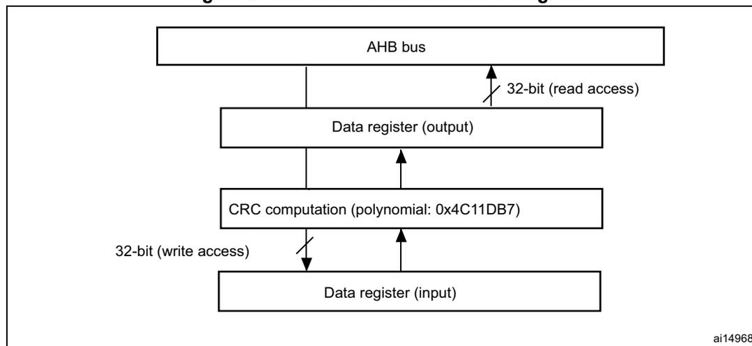
ai14968
3.3 CRC functional description
The CRC calculation unit mainly consists of a single 32-bit data register, which:
- • is used as an input register to enter new data in the CRC calculator (when writing into the register)
- • holds the result of the previous CRC calculation (when reading the register)
Each write operation into the data register creates a combination of the previous CRC value and the new one (CRC computation is done on the whole 32-bit data word, and not byte per byte).
The write operation is stalled until the end of the CRC computation, thus allowing back-to-back write accesses or consecutive write and read accesses.
The CRC calculator can be reset to 0xFFFF FFFF with the RESET control bit in the CRC_CR register. This operation does not affect the contents of the CRC_IDR register.
3.4 CRC registers
The CRC calculation unit contains two data registers and a control register. The peripheral The CRC registers have to be accessed by words (32 bits).
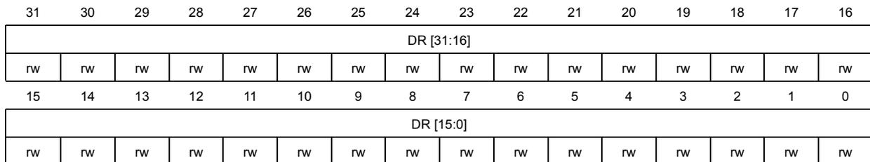
3.4.1 Data register (CRC_DR)
Address offset: 0x00
Reset value: 0xFFFF FFFF
| 31 | 30 | 29 | 28 | 27 | 26 | 25 | 24 | 23 | 22 | 21 | 20 | 19 | 18 | 17 | 16 |
| DR [31:16] | |||||||||||||||
| rw | rw | rw | rw | rw | rw | rw | rw | rw | rw | rw | rw | rw | rw | rw | rw |
| 15 | 14 | 13 | 12 | 11 | 10 | 9 | 8 | 7 | 6 | 5 | 4 | 3 | 2 | 1 | 0 |
| DR [15:0] | |||||||||||||||
| rw | rw | rw | rw | rw | rw | rw | rw | rw | rw | rw | rw | rw | rw | rw | rw |
Bits 31:0 Data register bits
Used as an input register when writing new data into the CRC calculator.
Holds the previous CRC calculation result when it is read.
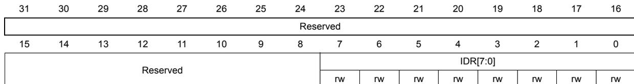
3.4.2 Independent data register (CRC_IDR)
Address offset: 0x04
Reset value: 0x0000 0000
| 31 | 30 | 29 | 28 | 27 | 26 | 25 | 24 | 23 | 22 | 21 | 20 | 19 | 18 | 17 | 16 |
| Reserved | |||||||||||||||
| 15 | 14 | 13 | 12 | 11 | 10 | 9 | 8 | 7 | 6 | 5 | 4 | 3 | 2 | 1 | 0 |
| Reserved | IDR[7:0] | ||||||||||||||
| rw | rw | rw | rw | rw | rw | rw | rw | ||||||||
Bits 31:8 Reserved, must be kept at reset value.
Bits 7:0 General-purpose 8-bit data register bits
Can be used as a temporary storage location for one byte.
This register is not affected by CRC resets generated by the RESET bit in the CRC_CR register.
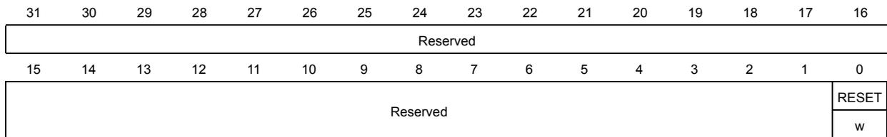
3.4.3 Control register (CRC_CR)
Address offset: 0x08
Reset value: 0x0000 0000
| 31 | 30 | 29 | 28 | 27 | 26 | 25 | 24 | 23 | 22 | 21 | 20 | 19 | 18 | 17 | 16 |
| Reserved | |||||||||||||||
| 15 | 14 | 13 | 12 | 11 | 10 | 9 | 8 | 7 | 6 | 5 | 4 | 3 | 2 | 1 | 0 |
| Reserved | RESET w | ||||||||||||||
Bits 31:1 Reserved, must be kept at reset value.
Bit 0 RESET bit
Resets the CRC calculation unit and sets the data register to 0xFFFF FFFF.
This bit can only be set, it is automatically cleared by hardware.
3.4.4 CRC register map
The following table provides the CRC register map and reset values.
Table 6. CRC calculation unit register map and reset values
| Offset | Register | 31-24 | 23-16 | 15-8 | 7 | 6 | 5 | 4 | 3 | 2 | 1 | 0 |
|---|---|---|---|---|---|---|---|---|---|---|---|---|
| 0x00 | CRC_DR | Data register | ||||||||||
| Reset value | 0xFFFF FFFF | |||||||||||
| 0x04 | CRC_IDR | Reserved | Independent data register | |||||||||
| Reset value | 0x00 | |||||||||||
| 0x08 | CRC_CR | Reserved | RESET | |||||||||
| Reset value | 0 | |||||||||||